Chapter 2. Designing an Event Poster
Chapter Objectives
Chapter Learning Objectives
![]() Create a new project and identify the correct document setup settings to use for different publishing projects.
Create a new project and identify the correct document setup settings to use for different publishing projects.
![]() Add ruler guides to a document.
Add ruler guides to a document.
![]() Create shapes through drawing and combine common shapes such as ellipses, rectangles, polygons, and lines.
Create shapes through drawing and combine common shapes such as ellipses, rectangles, polygons, and lines.
![]() Understand the use of layers.
Understand the use of layers.
![]() Add and resize images.
Add and resize images.
![]() Add and format text.
Add and format text.
![]() Identify different ways to colorize artwork.
Identify different ways to colorize artwork.
![]() Identify the right PDF settings for different publications and uses.
Identify the right PDF settings for different publications and uses.
Chapter ACA Objectives
For full descriptions of objectives, download the printable chart from your account on peachpit.com. See pages xi–xii.
DOMAIN 2.0
UNDERSTANDING PRINT AND DIGITAL MEDIA PUBLICATIONS
2.1, 2.2, 2.3, 2.4, 2.5
DOMAIN 3.0
UNDERSTANDING ADOBE INDESIGN CC
3.1, 3.2, 3.3, 3.4, 3.6, 3.8
DOMAIN 4.0
CREATING PRINT AND DIGITAL MEDIA PUBLICATIONS USING ADOBE INDESIGN
4.1, 4.2, 4.4
DOMAIN 5.0
PUBLISH, EXPORT, AND ARCHIVE PAGE LAYOUTS USING ADOBE INDESIGN
5.1
In this first hands-on project, you’ll design an event poster that is going to be printed commercially. As part of this project, you’ll learn how to create a new document in InDesign, add various visual elements, images, and text, as well as apply color to objects.
You’ll also learn how to submit your design as a Portable Document Format (PDF) proof to your client for review and as a press-ready PDF to your printer for production.
Starting the Project
As you start working in graphic design, you will likely create many different InDesign documents. You may need to design documents for print, such as a poster, report, or newsletter. Or perhaps you’ll be working on a magazine that contains interactive slideshows or videos that is destined to be viewed on tablets or mobile devices. Or, maybe you need to design eBooks that will be read in an interactive form. You can create all these designs with InDesign, but you’ll start with a printed event poster in this chapter (Figure 2.1).

![]() ACA Objective 4.1
ACA Objective 4.1
Creating a New Document
When creating a new document, first ask yourself: What is the intent of my document? Where will it be published? On which platform? As discussed at the end of the previous chapter, InDesign gives you the choice of three document intents:
![]() Print
Print
![]() Web
Web
![]() Digital Publishing
Digital Publishing
Note
This chapter supports the project created in video lesson 2. Go to the Project 2 page in the book’s Web Edition to watch the entire lesson from beginning to end.
For an event poster that will be posted in shop windows or on notice boards, the intent is print. Even if the same poster is posted as a Portable Document Format (PDF) or graphic on a website later on, print is the intent to start with. Choosing Print means you intend to mix colors used in designs with Cyan, Magenta, Yellow, and Black (CMYK) inks, which is different than mixing with Red, Green, and Blue (RGB). Consider the following question: What two colors would you use to mix orange? If you needed to pick from CMYK, what two colors would that be? Now try answering that same question mixing RGB colors.
Starting your document with print intent does not mean you cannot use RGB in the design at all. A combined RGB/CMYK workflow is a common practice. For instance, you could specify swatch colors in CMYK, and use photos originating from digital cameras, which capture in RGB. Placing these photos without converting them to CMYK first means you retain their maximum tonal range for the web version of the design. Meanwhile, the RGB photos can be converted to CMYK as part of the file export to PDF for delivery to your printer.
When setting up a new InDesign document for print, be sure to ask yourself some key questions before you jump into the program:
![]() What will the finished page size for the print publication be?
What will the finished page size for the print publication be?
![]() Will any design elements, such as background graphics and photos, run up to the edges of the page?
Will any design elements, such as background graphics and photos, run up to the edges of the page?
![]() Which area of the page will be the image area (that is, the area that contains most of the content, such as text and images)?
Which area of the page will be the image area (that is, the area that contains most of the content, such as text and images)?
![]() Video 2.1
Video 2.1
![]() Video 2.2
Video 2.2
![]() Will the pages of multipage documents be bound? Smaller newsletters might use saddle-stitch binding, which binds folded sheets by putting staples through the spine.
Will the pages of multipage documents be bound? Smaller newsletters might use saddle-stitch binding, which binds folded sheets by putting staples through the spine.
With these answers in mind, you’re ready to create a new document for your project in InDesign. For a single-page poster design destined for print, the new document setup is relatively simple:
1. Choose File > New > Document (Figure 2.2).

2. Select Preview so you can see how the changes affect the document setup.
3. Select Print from the Intent menu.
4. Select Tabloid from the Page Size menu and click the Portrait icon for Orientation. You can also enter custom Width and Height measurements here.
5. Deselect Facing Pages.
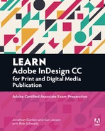
Posters or flyers are designed as standalone pages. In contrast, publications such as books or magazines use facing pages. Facing pages are placed on either side of the spine or fold. Creating a new document with Facing Pages selected displays the left and right pages of the document side by side, with the spine in the middle (Figure 2.3).
6. Next, set the Columns and Margins settings for your document: Enter the margin settings and number of columns as well as the gutter amounts.

Note
When working with a facing-pages document, the left and right margins become inside margin (toward the spine) and outside margin (the trim edge, away from the spine) settings.
7. To specify bleed and slug values, click the disclosure triangle to the left of Bleed And Slug (Figure 2.5).

Note
Depending on the type of print publication, bleed values vary. A business card might require a smaller bleed than a saddle-stitched magazine or a bound book. Always consult with your printer regarding the bleed amount required for a print project.
8. Enter the bleed or slug amounts.
The bleed is an area outside the perimeter of the printable page. When content must print to the edge of a page, extending the artwork into the bleed area avoids slight variations that show white (or paper-colored) edges when pages are trimmed to their finished size. A bleed of 1/8 of an inch (0.125 in) on all sides before a publication is trimmed is generally sufficient. For a poster or postcard design, you need to set the bleed for all four sides.
The slug area falls outside the bleed area and is used for information such as print instructions or project sign-off instructions.
9. Click OK to close the New Document dialog box, and start working on your design.
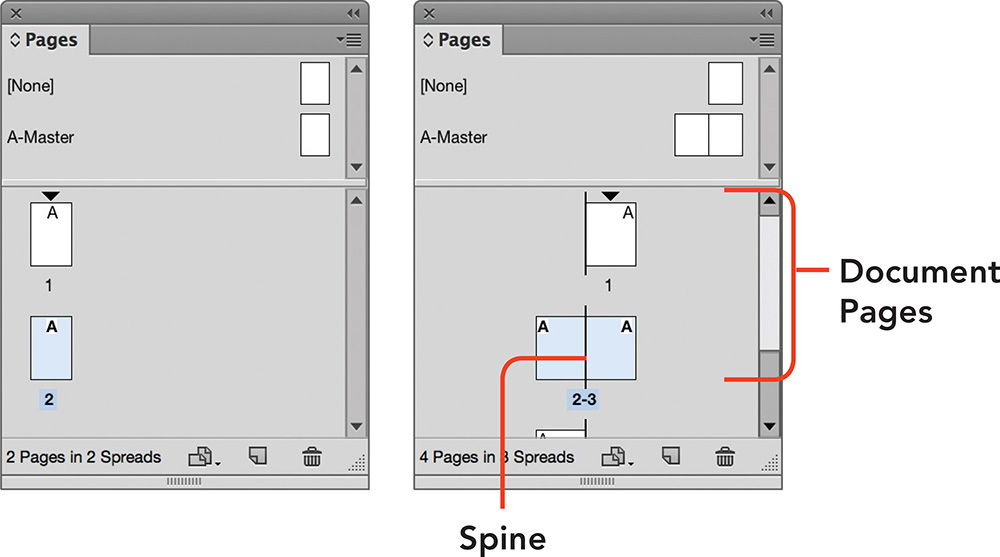
As you start working through the event poster project, consider viewing the finished poster design side by side with your working document, so you can check your progress and compare results.
To view two open documents side by side, do one of the following:
![]() Select 2-Up from the Arrange Documents menu in the Application bar (Figure 2.6).
Select 2-Up from the Arrange Documents menu in the Application bar (Figure 2.6).
![]() Choose Window > Arrange > Tile.
Choose Window > Arrange > Tile.
To bring all the document tabs back into one window, do one of the following:
![]() Select Consolidate All from the Arrange Documents menu in the Application bar.
Select Consolidate All from the Arrange Documents menu in the Application bar.
![]() Choose Window > Arrange > Consolidate All Windows.
Choose Window > Arrange > Consolidate All Windows.
![]() ACA Objective 3.4
ACA Objective 3.4
Using Ruler and Smart Guides
Creating a new document automatically adds a number of nonprinting guides for margins, columns, bleed, and slug to your page. Along with these guides, you can also add ruler guides to help position the elements of the poster.
Displaying Ruler Guides
Ruler guides are guides you add manually to further assist with the alignment of objects on your page. To add ruler guides, first ensure that the rulers are visible at the top and left of the document window.
To show or hide rulers, do one of the following:
![]() Choose View > Rulers.
Choose View > Rulers.
![]() Press Ctrl+R (Windows) or Command+R (Mac OS).
Press Ctrl+R (Windows) or Command+R (Mac OS).
![]() Select Rulers from the View Options menu in the Application bar.
Select Rulers from the View Options menu in the Application bar.
Shortcut
You can also drag a guide across the pasteboard area by Ctrl-dragging (Windows) or Command-dragging (Mac OS) from the ruler. Pressing the Shift key when dragging a guide from the ruler snaps the guide to even ruler increments.
Adding and Moving Ruler Guides
To add individual ruler guides (Figure 2.7):
1. Drag a guide from the ruler to the page.
2. Drag a guide from the ruler to the pasteboard area to create a guide across the page spread.

Ruler guides are cyan (kind of an aqua color) by default.
To reposition an existing ruler guide:
1. Using the Selection tool (![]() ), click to select the guide.
), click to select the guide.
2. Drag the guide to its preferred position. When the guide is selected, you can also enter horizontal (Y) or vertical (X) position values in the Control panel (Figure 2.8).

Figure 2.8 Horizontal and vertical ruler guides that are selected, so that the exact position can be set in the Control panel
![]() Choose View > Grids & Guides > Lock Guides.
Choose View > Grids & Guides > Lock Guides.
To delete a single ruler guide:
1. Using the Selection tool, click to select the guide.
2. Press Delete or Backspace.
To delete all of the ruler guides across a spread (Figure 2.9):
1. Right-click (Windows) or Control-click (Mac OS) in the vertical or horizontal ruler.
2. Select Delete All Guides On Spread from the context menu, or choose View > Grids & Guides > Delete All Guides On Spread.

Creating Evenly Spaced Ruler Guides
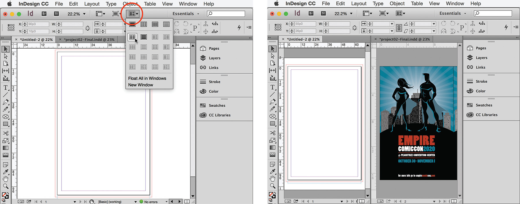
When you need to create ruler guides that are equally distributed across a page, the “drag guide from ruler” technique becomes tedious. You would need to know the exact page width and use a calculator to figure out where to place the guides. Thankfully, the Create Guides (Figure 2.10) command lets you distribute guides across a page or between margins.
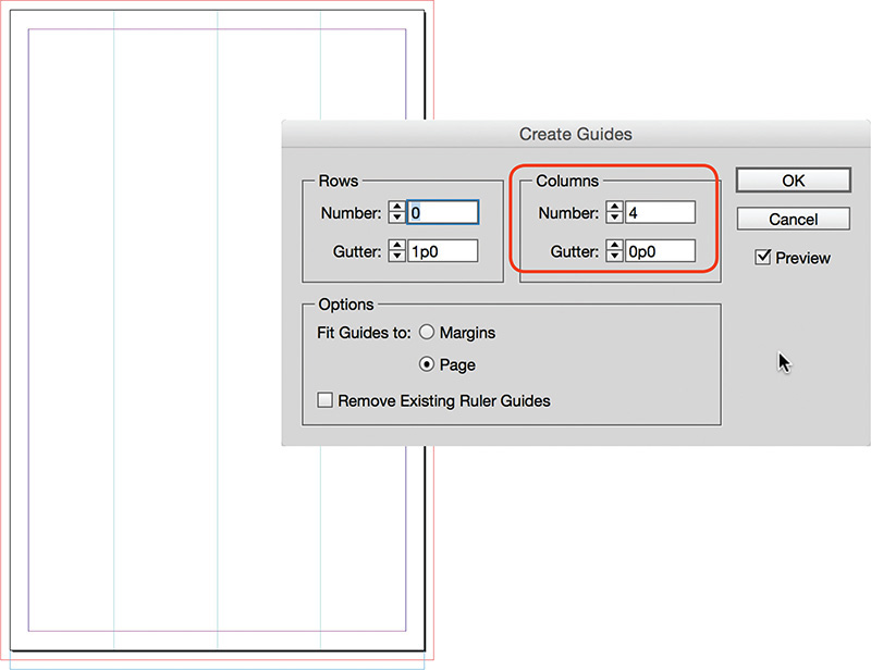
Figure 2.10 Using Create Guides to add three ruler guides that are equally distributed across the page
To create equally distributed guides:
1. Choose Layout > Create Guides.
2. Select Preview to see the changes as you make them.
3. Set the number of rows or columns, and gutter amounts.
4. Under Options, select Margins to distribute the guides between the margins, or Page to distribute the guides across the page width or depth.
5. To clear any previously added ruler guides, select Remove Existing Ruler Guides.
6. Click OK.
Snapping to Guides
By default, InDesign has View > Snap To Guides enabled. As you start to add or edit design elements, you will notice small tool pointer changes as an object snaps to a guide:
![]() When you move an object with the Selection tool, the move pointer (
When you move an object with the Selection tool, the move pointer (![]() ) changes to a hollow pointer (
) changes to a hollow pointer (![]() ) once the object snaps to a guide.
) once the object snaps to a guide.
![]() When you resize a frame or shape by dragging one of its bounding box handles, the double arrow appears hollow to indicate that releasing the mouse results in the frame edge snapping to a guide (Figure 2.11).
When you resize a frame or shape by dragging one of its bounding box handles, the double arrow appears hollow to indicate that releasing the mouse results in the frame edge snapping to a guide (Figure 2.11).

Figure 2.11 The tool pointer changes as the background rectangle is sized to show that the rectangle’s edge snaps to the margin guide.
Using Smart Guides
While ruler guides are great for aligning design elements, sometimes seeing too many on the page at once can make working on a design a little chaotic. This is where smart guides come to the rescue: These guides automatically appear as you drag or resize objects, then disappear when you finish.
To start using smart guides, first ensure you can see them. To view smart guides:
1. Set the Screen Mode to Normal.
2. Choose View > Guides & Grids > Smart Guides, or select Smart Guides from the View Options menu in the Application bar.
Note
If Smart Guides do not display, choose Edit > Preferences (Windows) or InDesign CC > Preferences (Mac OS), and then select Guides & Pasteboard. Make sure all of the Smart Guide Options are selected.
![]() Green guides appear when an object aligns with the center or edges of other objects that are visible in the document window (Figure 2.12).
Green guides appear when an object aligns with the center or edges of other objects that are visible in the document window (Figure 2.12).

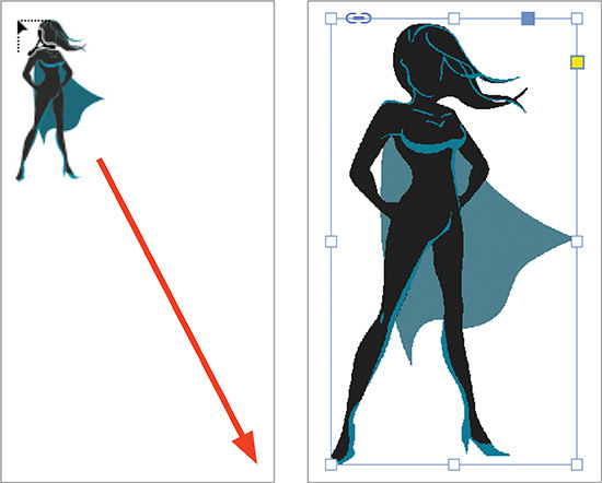
Figure 2.12 A green smart guide appears when the superhero image at right is moved upward and aligns with the top of the girl hero image to the left. Another green smart guide appears as the top of the superhero image aligns with the center of the female superhero image on the left.
![]() Green arrows display when objects are equal distances apart.
Green arrows display when objects are equal distances apart.
![]() When you resize an object, green arrows indicate that the object has the same width or height as another nearby object (Figure 2.13).
When you resize an object, green arrows indicate that the object has the same width or height as another nearby object (Figure 2.13).

Figure 2.13 The middle superhero figure (left) is moved horizontally until the image is an equal distance from the heroes on its left and right. A new shape is added (right) that is the same dimension as the superhero.
![]() Pink guides appear when an object aligns to the page center.
Pink guides appear when an object aligns to the page center.
![]() ACA Objective 3.3
ACA Objective 3.3
Preferences
As you start to work with InDesign, you’ll likely encounter behaviors or settings you’d like to tweak. The Preferences dialog box contains preference settings for 20 categories, and each category offers numerous adjustable options. That is a lot of settings that can be changed!
![]() Video 2.5
Video 2.5
Modifying Preferences
A preference you might consider changing is the units and measurements. An English (North American) install of InDesign uses picas as the default units of measurement. Picas are an old typographical unit of measurement. One pica is approximately 1/6 inch, and consists of 12 points. To learn more about old typographical units such as picas, ciceros, and agates, search the Internet.
Warning
To avoid unpredictable behavior of tools and features in InDesign, only modify preference settings when you have a very specific reason for doing so.
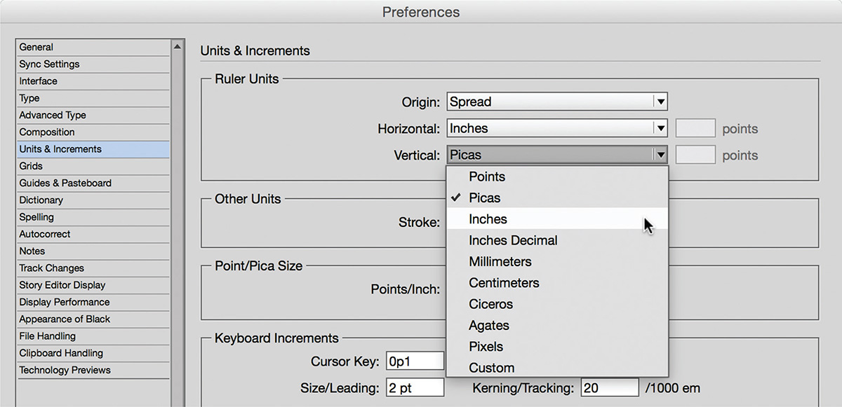
To change the measurement units to inches (Figure 2.14):
1. Choose Edit > Preferences (Windows) or InDesign CC > Preferences (Mac OS).
2. Select Units & Increments in the scroll list at left.
3. Change the Horizontal and Vertical Ruler Units from Picas to Inches, and click OK.
Tip
If you change a document-specific preference setting without having any InDesign documents open, the setting becomes a preference for all new documents you create.
Reverting to Default Preferences
1. Hold down the Shift+Ctrl+Alt (Windows) keys or the Shift+Ctrl+Option+Command (Mac OS) keys as you start up InDesign.
2. When the Startup Alert dialog box appears, click Yes.

Organizing Design Elements in Layers
Layers are like transparent pieces of paper that are placed on top of each other. Each can have their own design elements added to them. Layers are great for organizing related design elements and controlling the stacking order of objects. Layers are document based. Using layers, you can more easily isolate the design elements you are working on without accidentally changing other nonrelated objects. For example, when working on a magazine, you might work with separate layers for text, images, and background textures or colors.
![]() Video 2.3
Video 2.3
Changing Stacking Order within a Layer
When working with layers, you use the Layers panel. Every document has a default layer named Layer 1. Until you create more layers, everything you add to the page goes on Layer 1. When you add design elements, the last added element always appears above the previously added element. This order is referred to as the stacking order.
There are two ways to change the stacking order of objects in a layer.
First, you can change the order by using the various Object > Arrange commands:
1. Using the Selection tool, click the object.
2. Choose Object > Arrange and select one of the arrange options.
Bring To Front: Moves the selected object to the top of the stack
Bring Forward: Moves the selected object upward in the stack, one position at a time.
Send Backward: Moves the selected object downward in the stack, one position at a time.
Send To Back: Moves the selected object to the bottom of the stack.
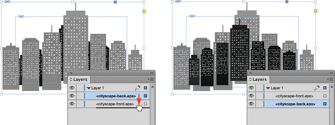
Another way to change the stacking order is by using the Layers panel:
1. Choose Window > Layers to show the Layers panel.
2. Click the disclosure triangle to the left of the layer name. All the objects within the layer are revealed.
3. Select the object on the page. When an object is selected, a colored dot appears to the right of the object in the Layers panel.
4. In the Layers panel, drag the object to a different position in the stack. Release the mouse button when a thicker line appears at the insertion point (Figure 2.16). You can also drag the colored dot to move the selected object to another layer or to change the object’s stacking order.
Creating and Naming Layers
To organize design elements in layers, start by creating new layers and renaming existing layers. Giving layers meaningful names clarifies the purpose of the layer.
To create a new layer (Figure 2.17):
1. Select New Layer from the Layers panel menu.
2. Enter a meaningful Name.
3. Notice all the other options, such as Color and Print Layer. As you get more familiar with layers, you may find a need for these.
4. Click OK.

Alternately, you can create a new layer this way:
![]() Click the Create New Layer button at the bottom of the Layers panel.
Click the Create New Layer button at the bottom of the Layers panel.
A new layer appears, automatically named Layer 1, Layer 2, etc.
No matter which method you choose, InDesign adds the new layer above the currently active layer.
Tip
Alt-click (Windows) or Option-click (Mac OS) the New Layer button to display the New Layer dialog box and Name the layer.
Shortcut
You can add a new layer below an active layer, press Ctrl (Windows) or Command (Mac OS) while you select New Layer Below from the Layers panel menu. To add a new layer above all other layers, press Shift+Ctrl (Windows) or Shift+Command (Mac OS) while you select New Top Layer from the Layers panel menu.
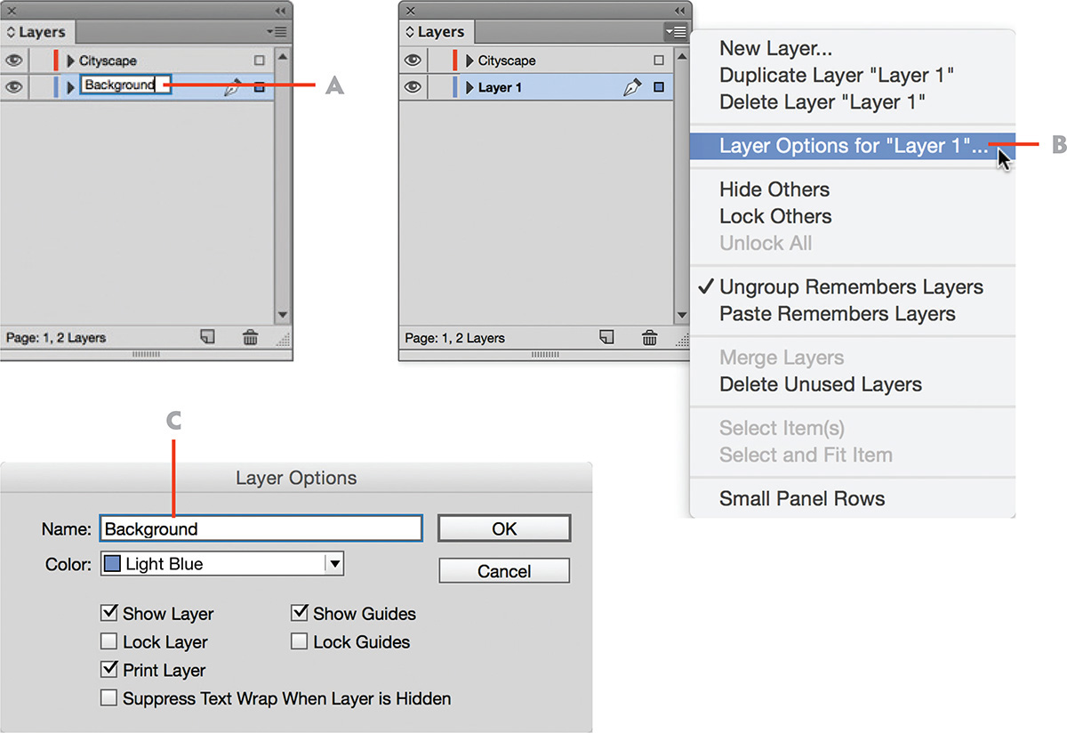
To rename a layer (Figure 2.18), you have the choice of three methods:
A. Select a layer in the Layers panel and click the layer name. Enter a new name and press Enter (Windows) or Return (Mac OS).
B. Select a layer, then select Layer Options For [name of your layer] from the Layers panel menu. Enter the Name in the Layer Options dialog box. Click OK.
C. Double-click the layer name. Enter the Name in the Layer Options dialog box and click OK.
Showing and Hiding Layers
The ability to hide layers enables you to focus on specific content—for example, edit text or fine-tune a drawing. You simply hide all the layers you are not currently working on. A small eye icon (![]() ) displays to the left of a visible layer’s name.
) displays to the left of a visible layer’s name.
To toggle layer visibility (Figure 2.19):
![]() Click the Show/Hide box to the far left of the layer name in the Layers panel.
Click the Show/Hide box to the far left of the layer name in the Layers panel.
All objects on the layer will show or be hidden.

To hide all layers except the active layer:
![]() Alt-click (Windows) or Option-click (Mac OS) the Show/Hide box to the left of the layer you want to isolate.
Alt-click (Windows) or Option-click (Mac OS) the Show/Hide box to the left of the layer you want to isolate.
Locking Layers
If you prefer to see the content of all layers, but don’t want to accidentally move objects around as you work on your design, consider locking the layers rather than hiding them. A locked layer displays a small padlock icon (![]() ) next to its name. When a layer is locked, you’ll see a warning dialog box (Figure 2.20) when trying to add content to the layer.
) next to its name. When a layer is locked, you’ll see a warning dialog box (Figure 2.20) when trying to add content to the layer.

To lock a layer and all of its objects (Figure 2.21):
![]() Click the Lock/Unlock box to the left of the layer name in the Layers panel.
Click the Lock/Unlock box to the left of the layer name in the Layers panel.

Instead of locking a layer, you can also lock or unlock individual objects, or groups:
1. Click the disclosure triangle to the left of the layer name in the Layers panel. This displays the sublayers so you can see the objects and groups; a small padlock icon appears to the left of any locked groups or objects.
2. Click a lock icon to unlock an object or group. To lock an object or group, click in the box immediately to the right of the Visibility icon.
Tip
You can also lock selected objects by choosing Object > Lock. If you lock and unlock objects frequently, it’s worth remembering the keyboard shortcut to toggle it on and off: Ctrl+L (Windows) or Command+L (Mac OS).
Changing Layer Order
As you add layers to a document, and add objects to those layers, you might find that the stacking order of the layers themselves needs reordering.
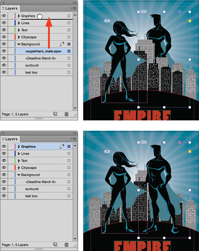
To move a layer and its objects to another position in the layer stack (Figure 2.22):
1. Select the layer in the Layers panel.
2. Drag it upward or downward until a line appears at the insertion point.

Designing Layers for Objects
Once you have created and named layers in your document, you can add new design elements to the designated layer. When you select a layer, it becomes the active drawing layer (![]() ) in InDesign:
) in InDesign:
![]() New objects such as text frames or graphic frames are automatically added to the active layer.
New objects such as text frames or graphic frames are automatically added to the active layer.
![]() Selecting an object to edit, such as a text frame, automatically selects its layer.
Selecting an object to edit, such as a text frame, automatically selects its layer.
At times, you might forget to select the correct layer when adding new design elements to a page. You can always move objects to a different layer.
To move an object to a different layer (Figure 2.23):
1. Select the object.
A colored dot to the right of the layer name indicates the selected item.
2. Drag the dot to another layer.
Or, you can move objects between layers using this method:
1. Click the disclosure triangle to the left of the Layer name.
2. Select the objects within the layer.
3. Drag to another layer.
Deleting a Layer
There might be times you created more layers than you need, for example multiple layers with images, where one layer would suffice. Or there might be a number of unused layers in the document.
Merging layers lets you delete layers and move any content to a target layer in a single step.
To merge layers:
1. Select the target layer.
2. Ctrl-click (Windows) or Command-click (Mac OS) the other layers.
3. Select Merge Layers from the Layers panel menu.
Only the target layer remains, and any content from other layers is moved to the target layer. Alternatively, you can choose to remove individual layers.
To delete a layer (Figure 2.24):
1. Select the layer in the Layers panel.
2. Choose Layer “[layer name]” from the Layers panel menu, or click the Delete Selected Layers button at the bottom of the Layers panel.

Note
If the layer contains any objects, a warning dialog appears when you try to delete the layer.
Tip
You can also delete a layer, by selecting it in the Layers panel and dragging it to the trashcan icon.
Adding Design Elements
With the new document created, guides added, and layers created, you are ready to start designing the poster. To do this, you will add colored shapes, lines, images, and text to create a beautiful composition.
![]() ACA Objective 2.2
ACA Objective 2.2
![]() ACA Objective 3.2
ACA Objective 3.2
Adding Shapes and Lines
InDesign documents consist of two primary page elements—shapes and lines—along with text and graphics in frames. Lines can be straight or curved, and they are used to join, organize, divide, direct, or construct other objects in your design. Geometric shapes, such as squares, circles, and triangles, are often used to visually combine related objects or to provide a hierarchy in the design.
The shape tools (Figure 2.25) and the Line tool (![]() ) enable you to add visual elements to designs.
) enable you to add visual elements to designs.
Creating Shapes
In the previous chapter, you learned about creating shapes with the shape tools. As a reminder:
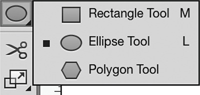
![]() To add a shape, select the Rectangle, Ellipse, or Polygon tool in the Tools panel. Drag across the page until the shape is created to the preferred size (Figure 2.26).
To add a shape, select the Rectangle, Ellipse, or Polygon tool in the Tools panel. Drag across the page until the shape is created to the preferred size (Figure 2.26).

![]() You can also click anywhere on the page to create a shape based on specific settings entered in the shape’s options dialog box (Figure 2.27).
You can also click anywhere on the page to create a shape based on specific settings entered in the shape’s options dialog box (Figure 2.27).

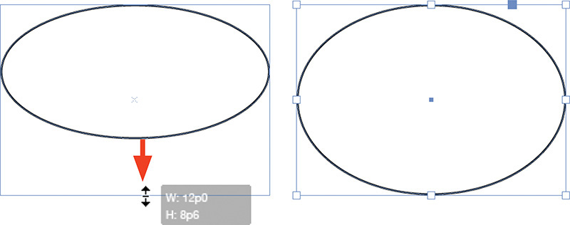
![]() At any stage, you can adjust the size of the shape by selecting it and editing its width (W) and height (H) settings in the Control panel. You can also drag out one of the bounding box handles of a selected shape (Figure 2.28).
At any stage, you can adjust the size of the shape by selecting it and editing its width (W) and height (H) settings in the Control panel. You can also drag out one of the bounding box handles of a selected shape (Figure 2.28).
By default, shapes created with the Rectangle tool (![]() ), Ellipse tool (
), Ellipse tool (![]() ), or Polygon tool (
), or Polygon tool (![]() ) have a fill color of [None] and a 1 pt black stroke. The color [None] is empty or see-through, and the shapes that are created are unassigned frames (as opposed to text frames or graphic frames).
) have a fill color of [None] and a 1 pt black stroke. The color [None] is empty or see-through, and the shapes that are created are unassigned frames (as opposed to text frames or graphic frames).
Note that you cannot click the Selection tool inside a shape with a fill of [None] to select it. You need to click on the frame’s edge. Think of it as trying to pick up an empty cup by sticking your fingers inside the cup. That does not really work. However, when you pick up the cup by its edge, you can lift it without any problems.
To select an unassigned frame with a fill color set to [None] (Figure 2.29):
1. Select the Selection tool.
2. Move the tool over the edge of the shape. The tool pointer changes from an arrow to an arrow with a dot to indicate that you can select the object.
3. Select the shape by clicking once. You can now resize, move, or delete the shape.

So, why do we see this selection issue for shapes created with the Rectangle, Ellipse, or Polygon tools? These tools create unassigned frames. Like those empty cups, you can’t pick them up by clicking in their middle.
The frame tools (Figure 2.30), on the other hand, create graphic frames to hold images. You can recognize a graphic frame by the X that displays inside it (when the Screen Mode is set to Normal). Graphic frames with a fill color set to [None] can be selected from their fill area. You can think of them as cups filled with a sticky sugar. When you grab the sticky contents, the cup comes too.

That leaves the question: Why would you want to use one tool over another, when both seemingly create similar shapes, albeit with a difference in behavior when the fill color is set to [None]. An obvious answer might be that you create a graphic frame because you want to import a graphic into it. However, the answer is not that simple: You actually can place a graphic into either type of frame.
Here’s why you create unassigned frames for shapes: Let’s assume you want to show a relationship between some design elements on the page, such as some text and graphics. Adding a line around the related items combines them visually. You create a rectangular shape with the fill color set to [None] and a stroke (Figure 2.31). When using an unassigned frame, you can easily select the objects that fall within the rectangular area. But when you use a graphic frame instead, you’ll need to click through the stack of objects to get to the objects below the frame.

Figure 2.31 A border created with the Rectangle tool (unassigned frame) at left, and Rectangle Frame tool (graphic frame) at right
Shortcut
To select objects in a stack with the Selection tool, Ctrl-click (Windows) or Command-click (Mac OS) to click through the stack of objects.
Creating Straight Lines
The line tool is used to create straight lines. To draw a line (Figure 2.32):
1. Select the Line tool.
2. Drag in any direction to create a line of preferred length.
3. With the line still selected, use the options on the Control or the Swatches and Stroke panels to change the width and color of the line.

Tip
To draw an orthogonal line (horizontal or vertical), press Shift as you drag to create the line. The Shift key can also be used to draw lines at 45-degree increments.
![]() ACA Objective 3.2
ACA Objective 3.2
Creating Combined Shapes
The Pathfinder panel and command in InDesign lets you combine two or more shapes to create new shapes.
![]() Video 2.9
Video 2.9
![]() Video 2.10
Video 2.10
To create a new shape using the Pathfinder panel:
1. Choose Window > Object & Layout > Pathfinder to show the Pathfinder panel.
2. Using the Selection tool, Shift-click multiple objects to combine them. You can also drag a marquee around the objects you want to select.
3. Click the preferred pathfinder button on the Pathfinder panel. Alternatively, you can choose Object > Pathfinder and select one of the Pathfinder options.
![]() Add: Unites two shapes into a new form (Figure 2.33).
Add: Unites two shapes into a new form (Figure 2.33).

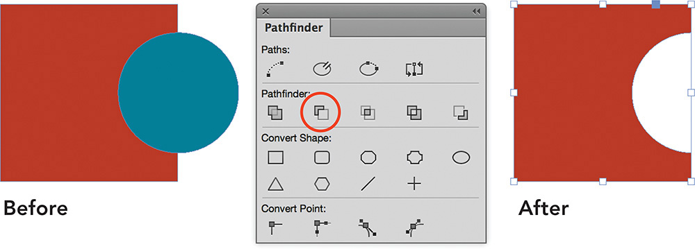
![]() Subtract: Knocks the topmost object out of the back object, with the resulting shape adopting the color of the backmost object (Figure 2.34).
Subtract: Knocks the topmost object out of the back object, with the resulting shape adopting the color of the backmost object (Figure 2.34).
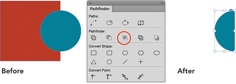
![]() Intersect: Retains only the area where two objects overlap, with the resulting shape taking on the color of the topmost object (Figure 2.35).
Intersect: Retains only the area where two objects overlap, with the resulting shape taking on the color of the topmost object (Figure 2.35).
![]() Exclude Overlap: Knocks out the areas where two objects overlap, with the resulting shape taking on the color of the topmost object (Figure 2.36).
Exclude Overlap: Knocks out the areas where two objects overlap, with the resulting shape taking on the color of the topmost object (Figure 2.36).

![]() Minus Back: Knocks the backmost object out of the front objects, with the resulting shape adopting the color of topmost object (Figure 2.37).
Minus Back: Knocks the backmost object out of the front objects, with the resulting shape adopting the color of topmost object (Figure 2.37).

In the following chapters, you will learn how to edit shapes and how to create freeform and natural shapes.
![]() ACA Objective 3.6
ACA Objective 3.6
Adding Color
Color is possibly the most powerful visual element you can use in your designs. It attracts attention, adds meaning, and evokes emotion in designs. For example, red is an eye-catching color that could also represent danger, and green often means safe. Think of traffic light colors: red means stop, yellow means caution, green means go. Blue, on the other hand, is a cooler color that reflects calmness. In contrast, pink is more reflective of love and kindness.
![]() Video 2.5
Video 2.5
![]() Video 2.14
Video 2.14
As an exercise, jot down some colors that spring to mind. Now, hop online and search for “psychology of colors.” Look for information about the colors you wrote down. Extend the search to discover more about the role color plays in marketing and branding.
Color Theory Basics
RGB color—which stands for red, green, and blue—is composed of the primary colors of light. Any device that captures or displays colors with light works with RGB color. When designing jobs exclusively for screens, such as digital publishing, eBooks, and websites, you would work with the Web or Digital Publishing document intent and mix colors using RGB.
CMYK color—which stands for cyan, magenta, yellow, and black (K)—is composed of the subtractive primary colors used in print, such as commercial presses and office printers. When designing jobs for print, use CMYK color combinations to build up your ink colors.
Process colors are made up of multiple color components. For instance, a CMYK process orange color might be 100% yellow and 50% magenta (Figure 2.38). An RGB process color for yellow might use 255 red and 255 green. In print terminology, process colors always refer to the mixing of CMYK colors.

Spot colors, in contrast to process colors, are premixed inks created specifically for print. The Pantone Color Matching System (PMS), for example, is used to define spot colors. Spot colors are used for jobs that require:
![]() Less than four colors.
Less than four colors.
![]() Accurate logo and branding colors.
Accurate logo and branding colors.
![]() Colors that can’t be achieved in process color-printing, such as a metallic or varnish.
Colors that can’t be achieved in process color-printing, such as a metallic or varnish.
You’ll learn more about spot versus process colors in Video Project 4 and later chapters.
Creating a Named Color with the Swatches Panel
In Chapter 1, you were introduced to applying stroke and fill colors to selected objects using the Control panel or Swatches panel. With the Swatches panel, you name the colors you create and they can be applied to page elements, included in styles (such as character styles and object styles). Additionally, if you edit a swatch, anywhere that it is applied reflects the color change; this enables you to quickly make global changes across a document. The Swatches panel makes it easy to create and use tints (shades) of color as well.
To create a new CMYK color swatch (Figure 2.39):
1. Choose Window > Color > Swatches to show the Swatches panel.
2. Choose New Color Swatch from the Swatches panel menu. Alternatively, Alt-click (Windows) or Option-click (Mac OS) the New Swatch button at the bottom of the Swatches panel.
3. In the New Color Swatch dialog box, make sure Process is selected from the Color Type menu.
4. Select CMYK from the Color Mode menu. Specify the Cyan, Magenta, Yellow, and Black values as desired.
5. Deselect Name With Color Value, and enter the new color’s name in the Swatch Name field.
6. Deselect Add to CC Library to add the color only to the active document, and click OK.

You can now apply the swatch to the stroke or fill of selected objects and text. Use the Swatches panel or Control panel for quick access to swatches.
Applying Color with the Color Panel
The Color panel allows you to mix and apply colors as you design. These colors are not named, and are therefore difficult to use consistently throughout a layout. Fortunately, you can add them to the Swatches panel.
To apply a stroke or fill color using the Color panel (Figure 2.40):
1. Choose Window > Color > Color to show the Color panel.
2. Using the Selection tool, click an object to apply a color. (You can also select text with the Type tool.)
3. Click the Stroke or Fill box in the Color panel or Tools panel.
4. From the Color panel menu, select CMYK when working on a document with print intent. Select RGB when working on documents for web or digital publishing.
5. Click anywhere in the color ramp to select a color, or use the sliders to adjust the color values.
6. To add the color as a reusable color to the Swatches panel, choose Add To Swatches from the Color panel menu.

Applying Color with the Color Picker
The Color Picker lets you mix colors based on any color mode by entering color values.
Tip
You can use the Color Picker to sample colors from anywhere on screen. This is particularly handy when you are working on digital media publications and want to pick up a color that is used on a web page, for example. To pick up a color: Double-click the Fill box, and click and hold the mouse on the eyedropper in the Color Picker dialog box, then move the pointer over the screen while holding the mouse button.
To add a CMYK swatch using the Color Picker (Figure 2.41):
1. Double-click the Fill box (or Stroke box) in the Color panel or Tools panel.
2. Enter the Cyan, Magenta, Yellow, and Black values.
3. Click Add CMYK Swatch.

Applying Color to a Line
To change the appearance of a line (Figure 2.42):
1. Using the Selection tool, click the line.
2. In the Swatches panel, click the Stroke box and then click a color swatch.
3. In the Stroke panel, adjust the thickness of the line by entering a new Width value or clicking the arrows next to the field.
4. In the Stroke panel, select a different option from the Type menu to create a wavy, dotted, or dashed line.

Tip
Remember that the Tools panel provides quick access to the Stroke/Fill box. In addition, the Control panel offers many options for formatting the selected object. As you get comfortable with InDesign, you will discover which options best suit your work style.
1. Select the object.
2. Click the Stroke or Fill Box.
3. Click [None] in the Swatches panel.
Tip
To quickly remove a stroke or fill color from a selected object, press / on the keyboard.
You’ll learn about more techniques and tools for capturing, creating, and applying colors in the next chapter.
![]() ACA Objective 3.6
ACA Objective 3.6
Gradients
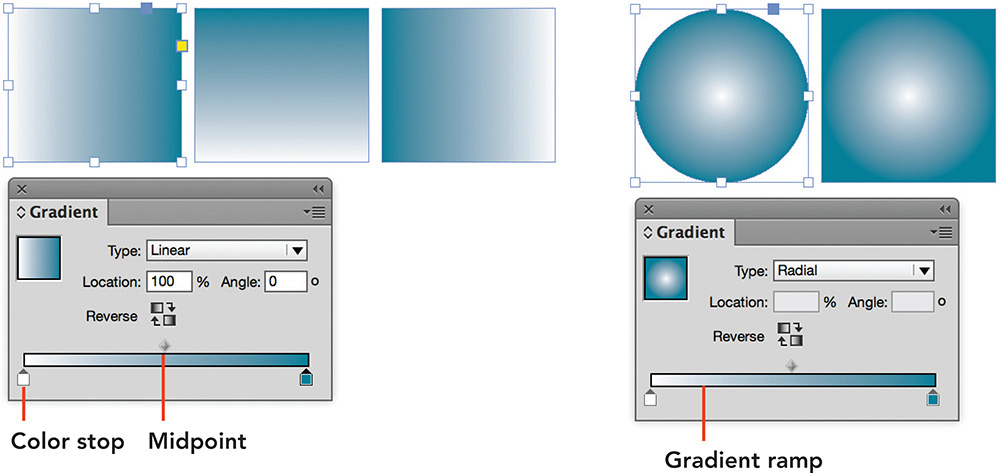
Gradients are blends between different colors or shades of color. A teal to white gradient would display a gradual blend that starts with a teal color at one end and gradually fades toward white at the other end. Gradients can break up the use of single tint colors and tones in a design, or be used to create interesting backdrops behind page designs or boxed content. You can apply two types of gradients to an object’s fill or stroke: linear and radial (Figure 2.43).
![]() Video 2.6
Video 2.6
Tip
If you plan to use gradients frequently, consider changing your workspace to Advanced. This will add the Gradient panel to the docked panels onscreen.
To create a blend between two colors, use the Gradient panel (Window > Color > Gradient), which contains a gradient ramp that shows a preview of the color blend. Each starting point for a color is marked by a color stop at the bottom of the gradient ramp. Between two color stops, the colors blend from the first to the second stop. You can add any number of colors to a gradient by adding more color stops. A movable midpoint controls where the two colors blend, with a 50% portion of each color.
To apply a gradient fill with the Gradient panel (Figure 2.44):
1. Choose Window > Color > Gradient to show the Gradient panel. Make sure that you can also see the Swatches panel.
2. Select an object.
3. Click the Gradient Swatch in the Gradient panel.
4. Select a color stop on the gradient ramp, then Alt-click (Windows) or Option-click (Mac OS) a swatch color in the Swatches panel. Alternately, you can drag and drop a swatch color onto the color stop.
5. Drag the gradient thumbnail in the top left of the Gradient panel into the Swatches panel to add a reusable Gradient Swatch.

![]() ACA Objective 2.5
ACA Objective 2.5
![]() ACA Objective 3.1
ACA Objective 3.1
![]() ACA Objective 4.4
ACA Objective 4.4
Adding Images and Graphics
Although you can complete a significant part of your design work in InDesign, images and graphics are generally created separately and supplied to you as individual files.
Pixel-based images, such as photos or photo compositions, are captured with a digital camera, scanned, or compiled in photo-editing programs, such as Adobe Photoshop. Vector-based graphics, such as a drawings, cartoons, logos, or technical drawings, are created in drawing programs, such as Adobe Illustrator. The shapes and lines that make up vector-based graphics are drawn mathematically, resulting in graphics that you can scale to different sizes without loss of quality. This means that vector-based graphics are resolution independent. In contrast, the quality of pixel-based images depends on their size and image resolution, measured in pixels per inch (ppi).
InDesign supports the import of native Photoshop and Illustrator files, as well as a range of other image and graphics file formats.
Understanding Image File Formats
For pixel-based images (Figure 2.45), commonly supported file formats are:
![]() Adobe Photoshop native files (PSD): PSD files may contain transparency, layers, and layer comps (snapshots of layer visibility, appearance, and position). Top-level layers and layer comps can be enabled or disabled within InDesign.
Adobe Photoshop native files (PSD): PSD files may contain transparency, layers, and layer comps (snapshots of layer visibility, appearance, and position). Top-level layers and layer comps can be enabled or disabled within InDesign.
![]() Tagged Image File Format (TIFF): TIFF files can be compressed and may contain layers and transparency.
Tagged Image File Format (TIFF): TIFF files can be compressed and may contain layers and transparency.
![]() Joint Photographic Experts Group files (JPEG): A compressed file format that significantly reduces file sizes. The format does not support transparency, layers, or spot color, and should be used with caution, as high compression rates could result in significant loss of quality. JPEG format is more commonly used for web images and digital publishing images.
Joint Photographic Experts Group files (JPEG): A compressed file format that significantly reduces file sizes. The format does not support transparency, layers, or spot color, and should be used with caution, as high compression rates could result in significant loss of quality. JPEG format is more commonly used for web images and digital publishing images.

For vector graphics (Figure 2.46) the more common formats are:
![]() Adobe Illustrator native files (AI): AI files retain transparency and layers. Top-level layers can be enabled or disabled within InDesign after import. During import, any available Illustrator artboard can be selected for import. Illustrator files appear as Adobe PDF Format in InDesign’s Links panel.
Adobe Illustrator native files (AI): AI files retain transparency and layers. Top-level layers can be enabled or disabled within InDesign after import. During import, any available Illustrator artboard can be selected for import. Illustrator files appear as Adobe PDF Format in InDesign’s Links panel.
![]() Encapsulated PostScript (EPS): An older file format that does not support transparency and is gradually being phased out. You will see this format used in the signage industry and with some older pagination systems newspapers use to place ads. Vector-based illustrations are fully opaque within the vector shape, but can be see-through outside the area defined by the vector shapes.
Encapsulated PostScript (EPS): An older file format that does not support transparency and is gradually being phased out. You will see this format used in the signage industry and with some older pagination systems newspapers use to place ads. Vector-based illustrations are fully opaque within the vector shape, but can be see-through outside the area defined by the vector shapes.
![]() Portable Document Format (PDF): A document format that is platform independent and can be viewed with the Adobe Acrobat Reader. PDF files embed images and graphics as well as fonts. The format is supported as an import format in InDesign. However, it is more commonly used to export finished art from InDesign for delivery to a printer or to provide a compatible version of the document for general viewing.
Portable Document Format (PDF): A document format that is platform independent and can be viewed with the Adobe Acrobat Reader. PDF files embed images and graphics as well as fonts. The format is supported as an import format in InDesign. However, it is more commonly used to export finished art from InDesign for delivery to a printer or to provide a compatible version of the document for general viewing.

These file formats work well for print publishing, and can also be used for digital publishing. With the exception of JPEG, the file formats discussed here are not supported in web design. Common file formats used when designing for web are JPEG, PNG, and GIF. When using non-web supported formats in InDesign projects for images or graphics, such as AI or PSD, InDesign converts these file formats to JPG, PNG, or GIF as appropriate.
Placing an Image into an Empty Frame
To place an image into an empty frame (Figure 2.47):
1. Choose Edit > Deselect All before placing content into InDesign.
2. Choose File > Place.
3. Navigate to a graphic or image file on your system and select it.
4. Deselect Show Import Options.
5. Click Open.
6. Position the pointer over the empty frame and click.

7. To resize the image in the frame, choose Object > Fitting and select one of the Proportional fitting options:
![]() Video 2.8
Video 2.8
![]() Fill Frame Proportionately: Sizes the graphic to fill the entire frame; some parts may be cropped at the edge of the frame. This is useful for placing photos.
Fill Frame Proportionately: Sizes the graphic to fill the entire frame; some parts may be cropped at the edge of the frame. This is useful for placing photos.
![]() Video 2.13
Video 2.13
![]() Fit Content Proportionately: Sizes the graphic to fit entirely in the frame; this is useful for placing logos, illustrations, and graphs.
Fit Content Proportionately: Sizes the graphic to fit entirely in the frame; this is useful for placing logos, illustrations, and graphs.
Placing and Sizing Images
To place and size image or graphic as you are placing it (Figure 2.48):
1. Choose Edit > Deselect All before placing content into InDesign.
2. Choose File > Place.
3. Navigate to the graphic or image file and select it.
4. Deselect Show Import Options.
5. Click Open. This “loads” the image on the pointer.
6. Drag with the loaded pointer to size and add the image to the page at the same time.
Shortcut
If you click on the page with a loaded pointer instead of dragging, you place the image at that location at 100% size.
Managing Links to Images
InDesign maintains a link to the original location of the placed image files. It does not embed the images; rather, it gives you a preview of the image for positional and sizing purposes. As you print or export your document, InDesign will locate the original image files and embed them into the exported format.
The Links panel (Window > Links) manages all the links in your InDesign documents, and will flag any missing or modified links (Figure 2.49). For example, if you retouch a photo after placing it in InDesign, you will need to update the link for the retouched version to display on the page.

Whenever you open a document that contains missing or modified links, a warning dialog appears that enables you to update modified links or relink missing links.
To quickly see link status in Normal screen mode, choose View > Extras > Show Link Badge. The link status appears to the top left corner of any placed images.
A modified link is flagged by a yellow warning triangle (![]() ), which indicates that the image had been edited since it was placed in InDesign. Updating modified links refreshes their preview in the document.
), which indicates that the image had been edited since it was placed in InDesign. Updating modified links refreshes their preview in the document.
To fix a modified link (Figure 2.50), do one of the following:
![]() Click the Link Badge on the image.
Click the Link Badge on the image.
![]() Click the Update Link button at the bottom of the Links panel.
Click the Update Link button at the bottom of the Links panel.
![]() Choose Update Link from the Links panel menu.
Choose Update Link from the Links panel menu.

Note
To minimize issues with linked images or graphics, consider placing all of the images and graphics used in your design in a folder called Links and keeping that folder as a subfolder of the project folder on your system.
A missing link is flagged with a red octagon, like a stop sign (![]() ) (Figure 2.51). Missing links appear when image files cannot be found in their original location. Moving an image to a different folder can cause a missing link, as can renaming an image.
) (Figure 2.51). Missing links appear when image files cannot be found in their original location. Moving an image to a different folder can cause a missing link, as can renaming an image.

To fix a missing link, do one of the following:
![]() Click the Link Badge on the image.
Click the Link Badge on the image.
![]() Click the Relink button or Relink From CC Libraries at the bottom of the Links panel.
Click the Relink button or Relink From CC Libraries at the bottom of the Links panel.
![]() Choose Relink or Relink From CC Libraries from the Links panel menu.
Choose Relink or Relink From CC Libraries from the Links panel menu.
Navigate to the image on your system or locate it in the CC Library.
Cropping and Resizing Images
A placed image or graphic in InDesign appears as content inside a graphic frame. Cropping images allows you to hide parts of an image that you don’t want to include in your design. You can crop an image by dragging the bounding box handles on the graphic frame. If you pause a second before you start dragging the handles, you’ll see the area of the image (content) that doesn’t fall within the graphic frame appear ghosted outside the frame area. For example, in Figure 2.52, cropping away the red building at left centers the focus of the image more on the skyscraper.

To crop an image (Figure 2.52):
1. Using the Selection tool, click the image.
2. Select one of the bounding box handles and drag inward.
To reposition an image within its graphic frame (Figure 2.53):
1. Using the Selection tool, click the Content Grabber in the center of the image.
2. Drag the image within the frame to the desired position.

Tip
You can also select an image and choose Object > Transform > Scale to enter a specific scale amount.
To resize an image within its graphic frame (Figure 2.54):
1. Using the Selection tool, click the Content Grabber in the center of the image. The image (content) is now selected within the frame.
2. Press Shift-drag a bounding box handle to constrain the image’s proportions.

To scale an image and its graphic frame simultaneously:
1. Using the Selection tool, select an edge of the graphic frame. Be sure the Content Grabber (donut shape) is not displaying in the middle of the image as it moves the image within the frame.
2. Ctrl-drag (Windows) or Command-drag (Mac OS) one of the corner bounding box handles on the image. Add the Shift key as well to maintain the proportions of the image as you drag.
![]() ACA Objective 3.2
ACA Objective 3.2
![]() ACA Objective 3.8
ACA Objective 3.8
![]() ACA Objective 4.2
ACA Objective 4.2
Adding and Formatting Text
Fonts and typography make up an important part of graphic design. For example, using different fonts and sizes to distinguish headings from the body copy (the main part of the text) helps organize information. Text formatting not only provides visual hierarchy, but can also communicate a specific message through font choice, size variations, color, alignment, and more. In the previous chapter, you learned a little about the Type tool (![]() ) and adding text frames to your designs. Now it’s time to dig a little deeper into formatting text.
) and adding text frames to your designs. Now it’s time to dig a little deeper into formatting text.
1. Choose Type > Add Fonts From Typekit. You can also choose Add Fonts From Typekit from the font menu in the Control panel or Character panel.
The Typekit web page opens in your default browser.
2. Enter your own preview text, then choose fonts based on classification (for example Sans Serif or Serif), as well as specific properties for Weight, Width, Height, Contrast, and a number of other settings. Typekit displays a list of fonts that meet the selected criteria.
3. When you find a font you want to use in your designs, move the pointer over the font and click Use Fonts.
4. In the Use This Family dialog box that appears, select which font styles you want to use, then click Sync Selected Fonts.
5. Once the fonts are synced, return to InDesign and you’ll be able to use the font in your design.

When editing or adding text, changing your workspace to the Typography workspace can help. This workspace gives you quick access to a multitude of typography-related panels, such as Character, Paragraph, Glyphs, and much more. These panels offer many text formatting options.
![]() Video 2.14
Video 2.14
![]() Video 2.15
Video 2.15
![]() Video 2.16
Video 2.16
You can set text formatting at two separate levels: paragraph and character. To adjust formatting at the character level, first select the text with the Type tool, then make the formatting changes. When adjusting paragraph-level formatting, it is sufficient to have the text insertion point set anywhere within a paragraph.
What’s the difference between the levels?
Paragraph formatting includes the horizontal alignment (left, center, right, justified) of the text, as well as spacing before or after paragraphs. Alignment controls how the text is positioned horizontally within the text frame.
Character formatting includes the font choice, font style (bold, italic), size, and leading. Leading or line spacing is the distance between lines of text within a paragraph. InDesign by default applies an automatic leading setting that is 120% of the font size. For instance, a 10-point font would be set to 12-point leading.
To adjust chararacter formatting (Figure 2.56):
![]() Click the Character Formatting Controls button (
Click the Character Formatting Controls button (![]() ) in the Control panel, or choose Type > Character to show the Character panel.
) in the Control panel, or choose Type > Character to show the Character panel.

To learn more about character formatting controls, position the mouse over each icon in the Control panel; a tool tip reveals what the control does.
1. Select the text.
2. Click the Fill box in the Tools, Swatches, or Control panel.
3. Select a color from the Swatches panel or Control panel.
To adjust paragraph formatting (Figure 2.57):
![]() Click the Paragraph Formatting Controls button (
Click the Paragraph Formatting Controls button (![]() ) in the Control panel, or choose Type > Paragraph to show the Paragraph panel.
) in the Control panel, or choose Type > Paragraph to show the Paragraph panel.

Understanding Leading
The fact that leading (line spacing) is a character attribute by default can be a bit confusing. Shouldn’t leading apply to all of the text in a paragraph? When you set a fixed leading value, the leading amount is locked in and doesn’t change when you increase or decrease the font size of the text. You must select all the text in a paragraph, including the paragraph return ![]() , before changing the value (Figure 2.58). If you select only a few lines within a paragraph, the leading applies only to those few lines.
, before changing the value (Figure 2.58). If you select only a few lines within a paragraph, the leading applies only to those few lines.

1. Choose Edit > Preferences (Windows) or InDesign CC > Preferences (Mac OS).
2. Select Type from the scrolling list at left.
3. Under Type Options, select Apply Leading To Entire Paragraphs.
4. Click OK.


Figure 2.59 With auto leading, different font sizes in a single paragraph result in different leading values across the different lines in the paragraph.
Tip
To see the paragraph return ¶ characters, choose Type > Show Hidden Characters (with the Screen Mode set to Normal). All hidden (nonprinting) characters, such as spaces and tabs, display in the text.
![]() ACA Objective 5.1
ACA Objective 5.1
Submitting Your Poster
It is common practice for designers to send design proofs to their clients. In the early stages of project work, you would provide your client with a detailed project description, an overview of pricing, as well as a list of the various deliverables that you will provide. Early on in a project, deliverables might be sketches, rough layouts, or design proposals that show the client your ideas and progress. These early deliverables give your client an opportunity to provide suggestions, refinements, and other feedback. Near the end of a project, you typically provide proofs of your finished work so the client can sign off, or approve, the project. A proof sign-off takes you to the last deliverable: the finished delivery format. In the case of the event poster design, that would be the physical printed copies of the poster.
![]() Video 2.17
Video 2.17
Submitting Proofs to Clients
Proofs are generally submitted to clients in Portable Document Format (PDF) form via email. As a file format, PDF enables people to share, view, and print documents independently from any software or computer system. With PDF, clients can review an exact representation of a design without having InDesign, the document’s fonts, and the image files. PDFs can even contain form elements, 3D objects, movies, sound, and other interactive elements (Chapter 4 covers interactive PDFs in more detail).
When submitting a proof to a client via an email (Figure 2.60):
1. Choose File > Adobe PDF Presets > Smallest File Size.
2. Enter a specific Name for the PDF in the File Name (Windows), or Save As (Mac OS) field.
3. Navigate to the location where you want to save the PDF file.
4. Click Save. The Export Adobe PDF dialog box appears.
5. Click General in the scroll list at left.
6. Under Options, select View PDF After Exporting. Leave all other settings at the defaults.
7. Click Export.
8. If a warning dialog box indicates a change in the destination color space, click OK. Smallest File Size PDFs are converted to RGB from CMYK, which makes them a bit smaller; this is fine for proofing purposes.

The new PDF will open in Acrobat (either the free Adobe Acrobat Reader or any Adobe Acrobat Pro version you have installed). Ensure that the PDF is as expected, and then send it off to your client for review. Your client can print the PDF or review it onscreen in the free Adobe Acrobat Reader, add comments and other annotations to the PDF, and submit these back to you.
Some clients will want to “backproof” changes and see a new PDF for each round of changes you make. Others may say something like, “Make these changes and send it to the printer.” Save all these proofs and communication as a record of client instructions if any problems arise down the line. Do not accept verbal sign-offs.
Submitting a PDF to the Printer
Once your client signs off on the last proof for your poster design, you are ready to submit the poster to the printer. You can submit print designs in two ways: as a print-ready PDF or as a packaged InDesign file. PDFs are all-in-one files that contain the pages, fonts, illustrations, and graphics used. When submitting a packaged InDesign file, you collect all design components (InDesign file, fonts, and graphics) into a single folder. Chapter 3 will cover packaging in depth, so for now let’s focus on PDFs.
PDFs can be exported with different quality settings, and the PDF presets that ship with InDesign provide a great starting point. No matter which preset you choose, each will embed fonts and images and capture your design perfectly.
The following PDF Export Presets are available:
![]() High Quality Print: Retains transparency, leaves the document colors unchanged. Used for printing to desktop printers or proofing devices.
High Quality Print: Retains transparency, leaves the document colors unchanged. Used for printing to desktop printers or proofing devices.
![]() Press Quality: Retains transparency, embeds all fonts, converts colors to CMYK (but retains spot colors), retains high-resolution images. Used for submitting jobs to commercial printers.
Press Quality: Retains transparency, embeds all fonts, converts colors to CMYK (but retains spot colors), retains high-resolution images. Used for submitting jobs to commercial printers.
![]() Smallest File Size: Retains transparency, converts all colors to sRGB, an RGB color space that captures the common RGB colors that can be displayed across a range of different devices, such as computer screens, or scanners, compresses and downsamples images to lower resolution. Used for web- or email-ready PDFs.
Smallest File Size: Retains transparency, converts all colors to sRGB, an RGB color space that captures the common RGB colors that can be displayed across a range of different devices, such as computer screens, or scanners, compresses and downsamples images to lower resolution. Used for web- or email-ready PDFs.
PDF/X is an International Standards Organization (ISO) standard for the exchange of documents within the graphics and printing industry. A number of PDF Export presets meet ISO standard requirements.
![]() PDF/X-1a:2001: Flattens transparency, embeds all fonts, supports only CMYK and spot color, converts RGB color to CMYK, retains high-resolution images. Used to submit designs to commercial printers.
PDF/X-1a:2001: Flattens transparency, embeds all fonts, supports only CMYK and spot color, converts RGB color to CMYK, retains high-resolution images. Used to submit designs to commercial printers.
![]() PDF/X-3:2002: Flattens transparency, embeds all fonts, retains color (CMYK, spot, and RGB), embeds color profiles, retains high-resolution images. Used for combined CMYK/RGB print workflows (for example, when photos are placed in RGB and color swatches are defined as CMYK color).
PDF/X-3:2002: Flattens transparency, embeds all fonts, retains color (CMYK, spot, and RGB), embeds color profiles, retains high-resolution images. Used for combined CMYK/RGB print workflows (for example, when photos are placed in RGB and color swatches are defined as CMYK color).
![]() PDF/X-4:2008: Retains transparency, embeds all fonts, supports color models (CMYK, spot, and RGB), embeds color profiles, retains high-resolution images. Used for combined CMYK/RGB print workflows that don’t require transparency flattening.
PDF/X-4:2008: Retains transparency, embeds all fonts, supports color models (CMYK, spot, and RGB), embeds color profiles, retains high-resolution images. Used for combined CMYK/RGB print workflows that don’t require transparency flattening.
To learn more about the various PDF/X standards, enter “PDF/X and print industry” in your favorite search engine. You will find great in-depth articles out there.
When submitting a press-ready PDF to your printer, always consult with the printer regarding the preferred export settings. In some cases, they may provide a PDF preset file for you to import.
To submit a press-ready PDF to your printer (Figure 2.61):
1. Choose File > Export.
2. Enter a specific Name for the PDF in the File Name (Windows), or Save As (Mac OS) field.
3. Navigate to the location where you want to save the PDF file.
4. Select Adobe PDF (Print) from the Save As Type (Windows) or Format (Mac OS) menu.
5. Click Save. The Export Adobe PDF dialog box appears.
6. Select [Press Quality] from the Adobe PDF Preset menu.
7. Click Marks And Bleeds in the scroll list at left.
8. Under Marks, select Crop Marks, Registration Marks, and Page Information.
9. If your document contains bleeds, select Use Document Bleed Settings.
10. If your document includes a slug area and you want to add any print instructions, select Include Slug Area.
11. Click Export.
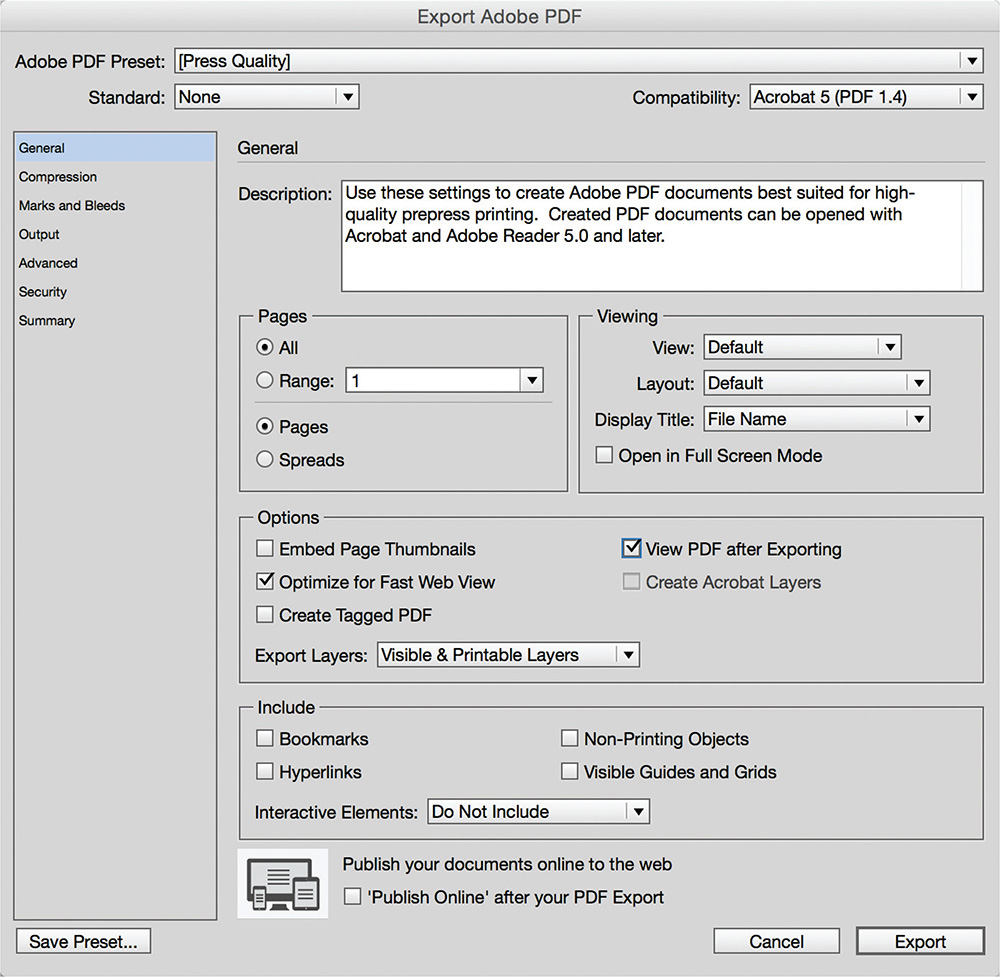
Figure 2.61 Exporting a finished event poster as a press-ready PDF with crop marks and bleed included
You are now ready to submit the press-ready PDF to the printer. The next time you see it, the poster will be in its finished printed format. Congratulations!