
Texture Views
So far, we have considered textures to be large buffers of data that have a specified format and consume a fixed amount of storage space. The amount of space depends on the format and on other parameters, such as the texture’s dimensions and whether it has mipmaps or not. However, conceptually, the format and to some extent the dimensions can be separated from the size of the underlying storage requirements of a texture. For example, many texture internal formats will consume the same number of bits per texel, and in some cases it is possible to interpret textures with various different dimensionalities—perhaps taking a single slice of an array texture and treating it as a single 2D texture.
OpenGL allows you to share a single data store among multiple textures, each with its own format and dimensions. First, a texture is created and its data store initialized with one of the data storage functions (such as glTextureStorage2D()). Next, we create a texture view of the “parent” texture. In effect, this increments a reference count to the underlying storage allocated for the first texture, giving each view a reference to it. To create a texture view, call glTextureView(), whose prototype is as follows:
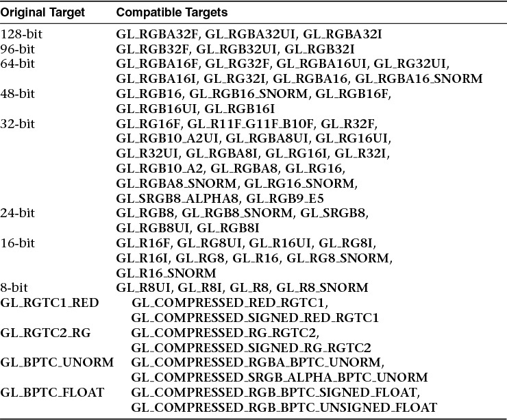
When creating views of existing textures, the target for the new texture must be compatible with the target of the original texture. The compatible targets are given in Table 6.6.

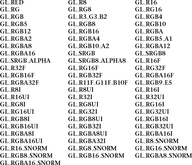
In addition to target compatibility, the internal format of the new view must be of the same format class (i.e., bits per texel) of the original parent texture. Table 6.7 lists the texture format classes and their compatible specific internal formats.
Given the format and target compatibility matrices in Table 6.7, it is possible to reinterpret data in a texture in multiple ways simultaneously. For example, it is possible to create two views of an RGB8 texture, one as unsigned normalized (returning floating-point data to the shader) and another as an unsigned integer texture (which will return the underlying integer data to the shader). Example 6.25 shows an example of how to achieve this.
Example 6.25 Creating a Texture View with a New Format
// Create two texture names - one will be our parent, one will
// be the view
GLuint tex[2];
glGenTextures(2, &tex);
// Bind the first texture and initialize its data store
// Here, the store will be 1024 x 1024 2D texture with mipmaps and
// the format will be GL_RGB8 - 8-bits per component RGB, unsigned
// normalized
glBindTexture(GL_TEXTURE_2D, tex[0]);
glTexStorage2D(GL_TEXTURE_2D, 10, GL_RGB8, 1024, 1024);
// Now,.create a view of the texture, this time using GL_RGB8UI so
// as to receive the raw data from the texture
glTextureView(tex[1], // New texture view
GL_TEXTURE_2D, // Target for the new view
tex[0], // Original texture
GL_RGB8UI, // New format
0, 10, // All mipmaps
0, 1); // Only one layer
As a second example, consider a case where you have a large 2D array texture and wish to take a single slice of the array and use it as an independent 2D texture. To do this, you can create a view with the target GL_TEXTURE_2D even though the original texture is GL_TEXTURE_2D_ARRAY. Example 6.26 shows an example of this.
Example 6.26 Creating a Texture View with a New Target
// Create two texture names - one will be our parent, one will
// be the view
GLuint tex[2];
glCreateTextures(1, GL_TEXTURE_2D_ARRAY, &tex[0]);
glCreateTextures(2, GL_TEXTURE_2D, &tex[1]);
// Initialize the data store of the first texture
// We are going to create a 2D array texture with a layer size
// of 256x256 texels and 100 layers.
glTextureStorage3D(tex[0], 8, GL_RGAB32F, 256, 256, 100);
// Now, create a GL_TEXTURE_2D view of the texture, extracting a single
// slice from the middle of the array
glTextureView(tex[1], // New texture view
GL_TEXTURE_2D, // Target for the new view
tex[0], // Original texture
GL_RGBA32F, // Same format as original texture
0, 8, // All mipmaps
50, 1); // Only one layer
Once a view of a texture has been created, it can be used in any place that you can use a texture, including image loads and stores or framebuffer attachments. It is also possible to create views of views (and views of those views, etc.), with each view holding a reference to the original data store. It is even legal to delete the original parent texture. So long as at least one view of the data exists, it will not be deleted.
Other use cases for texture views include aliasing data of various formats—for example, bit casting floating-point and integer data to enable atomic operations and OpenGL’s logic-op to be performed on floating-point data, which would normally not be allowed. Aliasing a single data store as both sRGB and linear data allows a single shader to simultaneously access the same data with and without sRGB conversion applied. A single-array texture may effectively have different format data stored in its slices by creating multiple array views of the texture and rendering different outputs to different slices of the texture. With some lateral thinking applied, texture views become a very powerful way to access and manage texture data.
Filtering
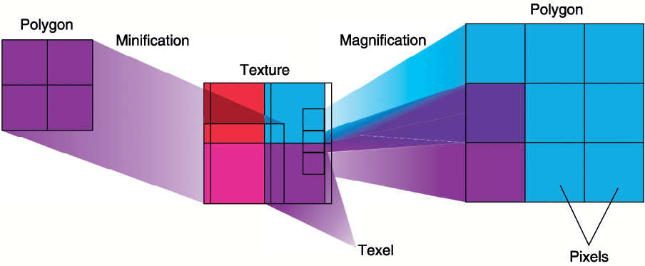
Texture maps may be linear, square, or rectangular, or even 3D, but after being mapped to a polygon or surface and transformed into screen coordinates, the individual texels of a texture rarely correspond directly to individual pixels of the final screen image. Depending on the transformations used and the texture mapping applied, a single pixel on the screen can correspond to anything from a tiny portion of a single texel (magnification) to a large collection of texels (minification), as shown in Figure 6.14. In either case, it’s unclear exactly which texel values should be used and how they should be averaged or interpolated. Consequently, OpenGL allows you to specify any of several filtering options to determine these calculations. The options provide different trade-offs between speed and image quality. Also, you can specify the filtering methods to be used for magnification and minification independently.
In some cases, it isn’t obvious whether magnification or minification is called for. If the texture map needs to be stretched (or shrunk) in both the x and y directions, magnification (or minification) is needed. If the texture map needs to be stretched in one direction and shrunk in the other, OpenGL makes a choice between magnification and minification16 that in most cases gives the best result possible. It’s best to try to avoid these situations by using texture coordinates that map without such distortion.
16. When a texture is enlarged by different amounts in the horizontal and vertical axes, this is referred to as anisotropic filtering. This is exposed by some OpenGL implementations in the form of an extension. However, this is not part of core OpenGL.
Linear Filtering
Linear filtering is a technique in which a coordinate is used to select adjacent samples from a discretely sampled signal and replace that signal with a linear approximation of the original. Consider the signal shown in Figure 6.15.
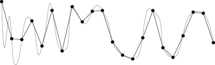
In Figure 6.15, the signal represented by the solid line has been discretely sampled at the points shown by the large dots. The original signal cannot be reconstructed by placing a straight line between each of the dots. In some areas of the signal, the linear reconstruction matches the original signal reasonably well. However, in other areas, the reconstruction is not faithful to the original, and sharp peaks that were present before resampling are lost.
For image data, the same technique can be applied. So long as the sampling rate (resolution) of the texture is high enough relative to the sharp peaks in the image data (details), a linear reconstruction of the image will appear to have reasonably high quality. The translation from a signal as shown in Figure 6.15 into a texture is easy to conceive when a 1D texture is considered. Simply place the samples into a 1D texture and reconstruct the original 1D image from those samples as needed.
To do this, OpenGL takes the texture coordinate that you pass it as a floating-point number and finds the two samples that lie closest to it. It uses the distance to each of those two points to create weights for each of the samples and then uses those weights to create a weighted average of them. Because linear resampling is separable17, OpenGL can apply this technique first in one dimension, and then again in a second dimension in order to reconstruct 2D images and even a third time for 3D textures. Figure 6.16 illustrates the process as applied to a 2D image.
17. A separable operation is one that can be deconstructed into two or more, usually similar passes over the data. In this case, we can apply one pass per dimension of the image data.
Not only can linear filtering be used to smoothly transition from one sample to the adjacent ones in 1D, 2D, and 3D textures, but it can also be used to blend texels sampled from adjacent mipmap levels in a texture. This works in a similar manner to that previously described. OpenGL calculates the mipmap level from which it needs to select samples, and the result of this calculation will often be a floating-point value with a fractional component. This is used just as a fractional texture coordinate is used to filter spatially adjacent texels. The two closest mipmaps are used to construct a pair of samples, and the fractional part of the level-of-detail calculation is used to weight the two samples into an average.
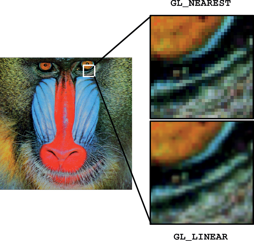
All of these filtering options are controlled by the texture filter modes in OpenGL’s sampler objects. As explained in “Sampler Objects” on page 288, the sampler object represents a collection of parameters that control how texels are read from textures. Two of those parameters, GL_TEXTURE_MAG_FILTER and GL_TEXTURE_MIN_FILTER, control how OpenGL filters textures. The first is used when the texture is magnified—that is, when the level of detail required is of a higher resolution than the highest-resolution mipmip level (by default, level 0) and represents cases where the mipmip calculation produces a level less than or equal to zero. Because, under magnification, only one mipmap level is used, only two choices are available for GL_TEXTURE_MAG_FILTER. These are GL_NEAREST and GL_LINEAR. The first disables filtering and returns the nearest texel to the sample location. The second enables linear filtering.
Texture minification is where mipmapping takes effect, and this is explained in some detail in the following sections.
Advanced
From a signaling-theory perspective, a texture needs to sample the original signal at at least twice the frequency of the highest-frequency data present. The original should be low-pass filtered to some frequency and then sampled at greater than twice that frequency. This gives enough samples to exactly reconstruct the original image. However, linear filtering fails to do this reconstruction and can lead to aliasing. Also, if the original filtering and 2X sampling are not done, aliasing and other artifacts can occur. This is discussed in more detail in Chapter 8, “Procedural Texturing,” while mipmapping as one technique for dealing with it is described here. You can also do custom filtering using texture gathers to improve over the artifacts of linear filtering. Gathering texels is discussed later in this chapter.
Using and Generating Mipmaps
Textured objects can be viewed, like any other objects in a scene, at different distances from the viewpoint. In a dynamic scene, as a textured object moves farther from the viewpoint, the ratio of pixels to texels in the texture becomes very low, and the texture ends up being sampled at a very low rate. This has the effect of producing artifacts in the rendered image due to undersampling of the texture data. For example, to render a brick wall, you may use a large texture image (say, 1024 × 1024 texels) when the wall is close to the viewer. But if the wall is moved farther away from the viewer until it appears on the screen as a single pixel, the sampled texture may appear to change abruptly at certain transition points.
To reduce this effect, we can prefilter the texture map and store the prefiltered images as successively lower-resolution versions of the full-resolution image. These are called mipmaps and are shown in Figure 6.17. The term mipmap was coined by Lance Williams when he introduced the idea in his paper “Pyramidal Parametrics” (SIGGRAPH 1983 Proceedings). Mip stands for the Latin multum in parvo, meaning “many things in a small place.” Mipmapping uses some clever methods to pack image data into memory.

When using mipmapping, OpenGL automatically determines which resolution level of the texture map to use based on the size (in pixels) of the object being mapped. With this approach, the level of detail in the texture map is appropriate for the image that’s drawn on the screen; as the image of the object gets smaller, the size of the texture map decreases. Mipmapping requires some extra computation and texture storage area. However, when it’s not used, textures that are mapped onto smaller objects might shimmer and flash as the objects move.
This description of OpenGL mipmapping avoids detailed discussion of the scale factor (known as λ) between texel size and polygon size. This description also assumes default values for parameters related to mipmapping. To see an explanation of λ and the effects of mipmapping parameters, see “Calculating the Mipmap Level” on page 329. Additional details on controlling λ from your application can be found in “Mipmap Level-of-Detail Control” on page 330.
The parameter GL_TEXTURE_MIN_FILTER controls how texels are constructed when the mipmap level is greater than zero. There are a total of six settings available for this parameter. The first two are the same as for magnification: GL_NEAREST and GL_LINEAR. Choosing one of these two modes disables mipmapping and causes OpenGL to only use the base level (level 0) of the texture. The other four modes enable mipmapping and control how the mipmaps are used. The four values are GL_NEAREST_MIPMAP_NEAREST, GL_NEAREST_MIPMAP_LINEAR, GL_LINEAR_MIPMAP_NEAREST, and GL_LINEAR_MIPMAP_LINEAR. Notice how each mode is made up of two parts and the token names are structured as GL_{A} MIPMAP_{B}. Here, {A} and {B} may both be either NEAREST or LINEAR. The first part, {A}, controls how the texels from each of the mipmap levels is constructed and works the same way as the GL_TEXTURE_MAG_FILTER setting. The second, {B}, controls how these samples are blended between the mipmap levels. When it’s NEAREST, only the closest mipmap level is used. When it’s LINEAR, the two closest mipmaps are linearly interpolated.
To illustrate the effect of the GL_TEXTURE_MIN_FILTER parameter on a mipmapped texture, Figure 6.18 shows how each affects a simple checker-type pattern at different resolutions in a mipmap pyramid. Notice how with the intra-mipmap filter specified as NEAREST (as in GL_NEAREST_MIPMAP_NEAREST and GL_NEAREST_MIPMAP_LINEAR), the checkerboard pattern becomes quite evident, whereas when it is LINEAR (as in GL_LINEAR_MIPMAP_NEAREST and GL_LINEAR_MIPMAP_LINEAR), it is less well defined and the texture appears blurred. Likewise, when the inter-mipmap filter mode is NEAREST (as in GL_NEAREST_MIPMAP_NEAREST and GL_LINEAR_MIPMAP_NEAREST), the boundary between the mipmap levels is visible. However, when the inter-mipmap filter is LINEAR (as in GL_NEAREST_MIPMAP_LINEAR and GL_LINEAR_MIPMAP_LINEAR), that boundary is hidden by filtering.

Figure 6.18 Effects of minification mipmap filters
GL_NEAREST_MIPMAP_NEAREST (top left), GL_LINEAR_MIPMAP_NEAREST (top right), GL_NEAREST_MIPMAP_LINEAR (bottom left), and GL_LINEAR_MIPMAP_LINEAR (bottom right).
To use mipmapping, you must provide all sizes of your texture in powers of 2 between the largest size and a 1 × 1 map. If you don’t intend to use mipmapping to go all the way to a 1 × 1 texture, you can set the value of GL_TEXTURE_MAX_LEVEL to the maximum level you have supplied, and OpenGL will not consider any further levels in its evaluation of texture completeness. If the highest resolution level of the texture is not square, one dimension will reach one texel in size before the other. In this case, continue making new levels with that dimension sized to one texel until the level becomes 1 × 1 texel in size. For example, if your highest-resolution map is 64 × 16, you must also provide maps of size 32 × 8, 16 × 4, 8 × 2, 4 × 1, 2 × 1, and 1 × 1. The smaller maps are typically filtered and downsampled versions of the largest map in which each texel in a smaller texture is a weighted average of the corresponding 4 texels in the higher-resolution texture. (Because OpenGL doesn’t require any particular method for calculating the lower-resolution maps, the differently sized textures could be totally unrelated. In practice, unrelated textures would make the transitions between mipmaps extremely noticeable, as in Figure 6.19.)
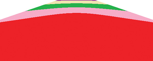
The image in Figure 6.19 was generated by creating a 64 × 64 texture and filling each of its 7 mipmap levels with a different color. The highest resolution level was filled with red, then green, blue, yellow, and so on down the mipmap pyramid. This texture was applied to a large plane extending into the distance. The farther the plane gets from the viewer, the narrower it becomes in screen space and the more compressed the texture becomes. OpenGL chooses successively higher mipmap levels (lower resolution levels) from the texture. To further illustrate the effect, the example sets the mipmap filtering mode to nearest and applies a bias to the calculated mipmap level.
To specify these textures, allocate the texture using glTextureStorage2D() and then call glTextureSubImage2D() once for each resolution of the texture map, with different values for the level, width, height, and image parameters. Starting with zero, level identifies which texture in the series is specified; with the previous example, the highest-resolution texture of size 64 × 64 would be declared with level = 0, the 32 × 32 texture with level = 1, and so on. In addition, for the mipmapped textures to take effect, you need to choose one of the mipmapped minification filters as described earlier.
OpenGL provides a function to automatically generate all of the mipmaps for a texture under application control. This function is called glGenerateTextureMipmap(), and it is up to the OpenGL implementation to provide a mechanism to downsample the high resolution images to produce the lower-resolution mipmaps. This will often be implemented internally by using a shader or perhaps the texture-filtering hardware. The technique used will generally be designed for performance over quality and will vary from implementation to implementation. If you want high-quality, well-defined results, it is best to generate and supply the mipmap images yourself. However, if you need to quickly generate a mipmap chain and are satisfied with whatever results you get, you can rely on glGenerateTextureMipmap() for this purpose.
Calculating the Mipmap Level
The computation of which mipmap level of a texture to use for a particular pixel depends on the scale factor between the texture image and the size of the polygon to be textured (in pixels). Let’s call this scale factor ρ, and also define a second value, λ, where λ = log2 ρ + lodbias. (Because texture images can be multidimensional, it is important to clarify that ρ is the maximum scale factor of all dimensions.)
lodbias is the level-of-detail bias for the sampler, a constant value set by calling glSamplerParameteri() with the pname parameter set to GL_TEXTURE_LOD_BIAS and is used to adjust λ. By default, lodbias = 0.0, which has no effect. It’s best to start with this default value and adjust in small amounts, if needed. If λ ≤ 0.0, the texel is smaller than the pixel, so a magnification filter is used. If λ > 0.0, a minification filter is used. If the minification filter selected uses mipmapping, λ indicates the mipmap level. (The minification-to-magnification switchover point is usually λ = 0.0, but not always. The choice of mipmapping filter may shift the switchover point.)
For example, if the texture image is 64 × 64 texels and the polygon size is 32 × 32 pixels, ρ = 2.0 (not 4.0), and therefore λ = 1.0. If the texture image is 64 × 32 texels and the polygon size is 8 × 16 pixels, ρ = 8.0 (x scales by 8.0, y by 2.0; use the maximum value), and therefore λ = 3.0.
The equations for the calculation of λ and ρ are as follows:
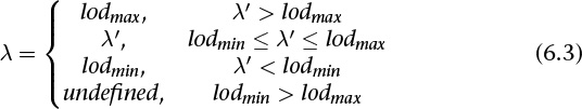
The calculation of mipmap level can be further controlled by a number of sampler parameters. In particular, the GL_TEXTURE_LOD_BIAS parameter may be used to bias λ. Once λ has been calculated, it may be clamped into a user-specified range, which is given by the parameters GL_TEXTURE_MIN_LOD and GL_TEXTURE_MAX_LOD, which are specified by passing those token values to glSamplerParameterf() (or to glTextureParameterf() if sampler objects are not in use). The default values for GL_TEXTURE_MIN_LOD and GL_TEXTURE_MAX_LOD are –1000.0 and 1000.0, respectively, allowing them to effectively pass through any value. The values of GL_TEXTURE_MIN_LOD and GL_TEXTURE_MAX_LOD are represented by lodmin and lodmax in the following equation.
The default parameters for GL_TEXTURE_MAG_FILTER and GL_TEXTURE_MIN_FILTER are GL_LINEAR and GL_LINEAR_MIPMAP_LINEAR, respectively. Notice that the default minification filter enables mipmapping. Textures allocated using the glTextureStorage2D() function always have a complete set of mipmaps, but these textures will still contain no data when they are newly created. This is a common source of errors for new OpenGL programmers; they forget to either change the filtering mode or fill in the mipmaps for newly created textures, resulting in their texturing code not working.
Mipmap Level-of-Detail Control
In addition to the parameters controlling lodmin, lodmax, and λbase during the calculation of λ, further control over the selected level of the mipmap pyramid is provided through the GL_TEXTURE_BASE_LEVEL and GL_TEXTURE_MAX_LEVEL parameters, which may be set using glSamplerParameteri(). GL_TEXTURE_BASE_LEVEL specifies the lowest mipmap level (i.e., highest resolution) that will be sampled, regardless of the value of λ, whereas GL_TEXTURE_MAX_LEVEL specifies the highest mipmap level (i.e., lowest resolution) that will be sampled. This can be used to constrain sampling to a subset of the mipmap pyramid.
One potential use for GL_TEXTURE_BASE_LEVEL is texture streaming. When using texture streaming, storage for the complete texture object is allocated using a function such as glTextureStorage2D() but the initial data is not loaded. As the application runs and new objects come into view, their texture data is loaded from lowest- to highest-resolution mipmap. To ensure that something meaningful is displayed to the user even when the complete texture has not yet been loaded, the value of GL_TEXTURE_BASE_LEVEL can be set to the highest-resolution mipmap level that has been loaded so far. That way, as more and more texture data is loaded, objects on the screen achieve higher and higher fidelity.
Advanced Texture Lookup Functions
In addition to simple texturing functions such as texture and texelFetch, several more variants of the texture fetch functions are supported by the shading language. These are covered in this subsection.
Explicit Level of Detail
Normally, when using mipmaps, OpenGL will calculate the level of detail and the resulting mipmap levels from which to sample for you. (See “Calculating the Mipmap Level” on page 329 for more details on how OpenGL calculates mipmap levels.) However, it is possible to override this calculation and specify the level of detail explicitly as an argument to the texture fetch function. The textureLod function takes this lod parameter in place of the bias parameter that would normally be optionally supplied to the texture function. Like other texture functions supported by GLSL, textureLod has many overloaded prototypes for the various types and dimensionalities of the supported sampler types. Some key prototypes of textureLod are as follows. (A full list is in Appendix C, “Built-in GLSL Variables and Functions.”)
Notice that because they don’t support mipmaps, samplerBuffer and samplerRect are missing from the supported sampler types for textureLod.
Explicit Gradient Specification
It is also possible to override the level-of-detail calculation for mipmapping at an earlier part of the process rather than explicitly giving the level-of-detail parameter directly. When the gradient texture functions are used, the partial derivative of the texture coordinates is given as a parameter. Some key prototypes are listed here. (A full list is in Appendix C, “Built-in GLSL Variables and Functions.”)
In the textureGrad functions, the variable ρ as described in “Calculating the Mipmap Level” on page 329 is essentially passed in using dPdx and dPdy. This can be useful when an analytic function for the derivative of a texture coordinate may be known or when a function that is not the derivative of the texture coordinate is required.
Texture Fetch with Offsets
Some applications require a number of texels around a region of interest or may need to offset the texture coordinates slightly during sampling. GLSL includes functions for doing this that will likely be more efficient than physically offsetting the texture coordinates in the shader. This functionality is exposed through an overloaded set of texture lookup functions called textureOffset, with some example prototypes as follows. (A full list is in Appendix C, “Built-in GLSL Variables and Functions.”)
Notice that for the textureOffset function, the offset parameter is an integer value. In fact, this must be a constant expression and must be with a limited range. This range is given by the built-in GLSL constants gl_MinProgramTexelOffset and gl_MaxProgramTexelOffset.
Projective Texturing
Projective texturing is employed when a perspective transformation matrix has been used to transform texture coordinates. The input to the transform is a set of homogeneous coordinates, and the resulting output of this transform is a vector whose last component is unlikely to be 1. The textureProj function can be used to divide through by this final component, projecting the resulting texture coordinate into the coordinate space of the texture. This is useful for techniques such as projecting decals onto flat surfaces (e.g., the halo projected by a flashlight) or in shadow mapping.18 Some example prototypes are given here. (A full list is in Appendix C, “Built-in GLSL Variables and Functions.”)
18. An in-depth example of shadow mapping is given in “Shadow Mapping” on page 413.
Texture Queries in Shaders
The following two built-in GLSL functions don’t actually read from the texture, but return information about the texture or about how it will be processed. The first function, textureQueryLod, retrieves mipmap information calculated by the fixed-function texture lookup hardware.
For each of these textureQueryLod() functions, there is a corresponding query, textureQueryLevels(), that returns the number of mipmap levels present.
Sometimes, it may be necessary to know the dimensions of a texture from which you are about to sample. For example, you may need to scale an integer texture coordinate representing an absolute texel location into a floating-point range suitable for sampling from the texture, or to iterate over all the samples in a texture. The textureSize function will return the dimensions of the texture at a specified level of detail. Its prototype is as follows. (A full list is in Appendix C, “Built-in GLSL Variables and Functions.”)
You can also find out, from within the shader, how many samples you have per texel when doing multisample texturing:
Gathering Texels
The textureGather function is a special function that allows your shader to read the four samples that would have been used to create a bilinearly filtered texel from a 2D texture (or cube map, rectangle texture, or array of these types). Typically used with single-channel textures, the optional comp component of the function allows you to select a channel other than the x or r component of the underlying data. This function can provide significant performance advantages when you need to sample many times from a single channel of a texture because, depending on the desired access pattern, it is possible to use this function to cut the number of texture lookups by three quarters.
Combining Special Functions
In addition to all of the special texturing functions, several more variants of these functions exist that combine features from multiple variants. For example, if you want to do projective texturing with an explicit level-of-detail or gradients (each is described in “Explicit Gradient Specification” in this chapter), you can use the combined functions textureProjLod or textureProjGrad, respectively. The combined functions using a 2D sampler are shown here. Variants of almost all of these functions exist for other dimensionalities and types of sampler, and a full list is in Appendix C, “Built-in GLSL Variables and Functions.”
Bindless Textures
So far, to use a texture in your shader, you have bound it to a texture unit, associated that texture unit with a sampler in the shader, and then read from the texture using built-in functions. OpenGL supports a fixed number of texture units globally, and the maximum number of textures a single shader can use is limited to as well. If your application uses a lot of textures, you will need to continuously bind and rebind textures between drawing each object in your scene. In terms of performance, applications can spend a significant amount of their time managing the set of objects bound to the context.
As an alternative, it is possible to use bindless textures, which, rather than an association of a sampler with a texture, allow the texture object itself to be represented as a 64-bit number. Rather than using sampler uniforms, we use sampler handles. The values of these handles are provided to us by OpenGL, and it doesn’t matter how the handle values are passed to the shader, so long as they make it there intact. For example, you could pass the 64-bit number inside a uniform block or vertex attribute, or even fetch it from a texture. Once you have the value of the 64-bit texture handle in your shader, you can construct a sampler from it. Samplers can also be constructed from pairs of 32-bit values. Once the sampler is constructed, it can be used like any other sampler in the shader to read texels from the texture. It’s also possible to place a sampler directly inside a uniform block, where it is defined in the application as a 64-bit integer value.
Bindless textures are supported in OpenGL only when the GL_ARB_bindless_texture extension is present, so before calling any of the following functions, it is important to make sure that the extension is supported. It is up to you to decide whether you want to have a nonbindless fallback path in your application or whether you prefer to ask your users to upgrade their graphics hardware or drivers.
Texture Handles
To retrieve the handle to a texture object, call one of the following:
Once you have the handle to the texture, the parameters of the texture (and the sampler) are “baked” into the handle. That is, even if you change the parameters of the texture or sampler, the handle will still refer to the parameters of the texture or sampler at the time you retrieved the handle. It’s possible to take advantage of this to, for example, grab a handle to the texture with one set of parameters, modify one of the parameters of the texture, such as the filtering mode or base level, and then grab a second handle to the texture to sample from it in a different way. If you change the contents of the texture, though, that new content will show up in any subsequent sampling your application does.
Texture Residency
Before you can actually use the handle in your shaders, you need to make sure that the texture itself is resident. This is a task that OpenGL normally does for you: When you bind textures to the context, OpenGL effectively has a list of all the textures that your shaders might access because they were previously limited to sampling from the set of bound textures. Before running your shader, OpenGL makes sure all the data for the bound textures are in the right pieces of memory and ready to be read. With bindless textures, the texture handles you’re accessing might come from anywhere. You could put them in memory and access them through a uniform buffer or even sample them from a texture, so OpenGL can’t tell what the working set is. This responsibility therefore falls to your application to tell OpenGL what needs to be accessible to your shaders and what does not.
To tell OpenGL which textures you’re potentially going to access, call
Although it’s best if your application keeps track of which textures are resident and which are not, you can ask OpenGL whether a texture is resident for a given handle. To do this, call
Handles returned from glMakeTextureHandleResidentARB() and glMakeTextureHandleNonResidentARB() remain valid until the texture is deleted. Once the texture is deleted, any handles produced from that texture become invalid and shouldn’t be used. The handles themselves are not explicitly deleted.
Sampling Bindless Textures
Once the handles representing your textures have been passed to the shader, you can construct a sampler handle from them and then use them as normal. Furthermore, it’s possible to place a sampler variable inside a uniform block and use it directly. In this case, the sampler inside the block has an in-memory layout identical to a GLuint 64 as seen by the host. Because of this, it’s possible to map a buffer and write the GLuint 64 typed handles returned from glGetTextureHandleARB() into the buffer directly. This is significantly faster than calling glBindTextureUnit(). Example 6.27 shows how to use bindless texture handles in a shader.
Example 6.27 Using Bindless Texture Handles in a Shader
#version 450 core
#extension GL_ARB_bindless_texture : require
in FS_INPUTS
{
vec2 i_texcoord;
flat int i_texindex;
};
layout (location = 0) out vec4 o_color;
layout (binding = 0) uniform ALL_TEXTURES
{
sampler2D my_textures[200];
};
void main(void)
{
o_color = texture(m_textures[i_texindex], i_texcoord);
}
As you will notice in Example 6.27, the uniform block ALL_TEXTURES contains 200 texture handles. Not only is that far more textures than are normally available to a shader in unextended OpenGL, but also it’s much, much faster to change which textures are referenced. By simply binding a new range of a buffer to the uniform binding point, a completely different set of 200 textures are made available to the shader.
Sparse Textures
In any large-scale application, textures are perhaps the most expensive type of resource in terms of memory consumption. Compressed textures help here but go only so far. In practice, most applications that include a large amount of texture data don’t actually require all of that data to generate any single frame. For example. if an object is very far away, the highest-resolution mipmaps of its textures likely won’t be sampled by its shader. If an object is outside the current view frustum or is occluded by another, closer object, it may not be rendered at all. We can take advantage of this by using sparse textures, which are textures that are logically complete but whose data is only partially populated.
Sparse textures are supported by OpenGL if the implementation advertises the GL_ARB_sparse_texture extension string. This is an optional feature but is quite widely exposed, so it’s worthwhile adding support for it to applications that use a large amount of texture data.
To create a sparse texture, we first create the texture object itself by calling glCreateTextures(). Next, we turn its GL_TEXTURE_SPARSE_ARB property on by calling glTextureParameteri(). Then, when we call glTextureStorage*D() on the texture, OpenGL will allocate virtual space for the texture but won’t actually allocate any physical memory for it. Because the texture allocation is virtual, we can create textures that are much larger than any that would fit in real memory. For example, a 2048 x 2048 x 2048 2D array texture with an internal format of GL_RGBA8 would normally consume 32 gigabytes of memory—far more than is found on current graphics cards. However, this fits comfortably into the virtual address space of a modern GPU. Example 6.28 illustrates how such a texture is created.
Example 6.28 Allocating a Large Sparse Texture
GLuint tex;
// First, create a texture object.
glCreateTextures(GL_TEXTURE_2D_ARRAY, 1, &tex);
// Now, turn its sparse property on
glTextureParameteri(tex, GL_TEXTURE_SPARSE_ARB, GL_TRUE);
// Now allocate the texture's virtual storage
glTextureStorage3D(tex, 11, GL_RGBA8, 2048, 2048, 2048);
After the code in Example 6.28 has executed, tex is the name of a texture object that has no backing store but is logically 2048 × 2048 × 2048 texels in size and consumes 32 gigabytes of virtual memory.
Sparse Texture Commitment
At this point, you have a perfectly usable texture. You can bind it to a texture unit and access it from a shader, or if you are using bindless textures, you can take its handle and use that instead of binding it. However, if you sample from it in your shaders, you will receive zeros. If you try to put data into it using glTextureSubImage2D(), the data will be thrown away because there is nowhere to store the data.
In order to physically back a sparse texture, we need to use the glTexturePageCommitmentEXT()19 function. This controls the commitment of individual pages of a sparse texture. Its prototype is
19. This function is listed with an EXT suffix because the GL_ARB_sparse_texture extension was introduced before the direct state access functionality was promoted to core status.
Sparse Texture Pages
The glTexturePageCommitmentEXT() function controls the commitment or backing of a texture object at the granularity of pages. A page is a region whose size is measured in texels. The size of the region is generally fixed in storage space; therefore, its size in texels will depend on the internal format of the texture. To determine the page size for a particular format, call glGetInternalformativ() with one of the GL_VIRTUAL_PAGE_SIZE_X, GL_VIRTUAL_PAGE_SIZE_Y, or GL_VIRTUAL_PAGE_SIZE_Z tokens.
An OpenGL implementation might support multiple page sizes for a given texture format because there’s more than one way to lay out a fixed number of texels in a regular region. To find out how many different page sizes are supported for a given internal format, call glGetInternalformativ() with the GL_NUM_VIRTUAL_PAGE_SIZES token. When querying the page size for a format, passing an array large enough to contain this number of integers will allow you to determine all available sizes. If OpenGL returns zero for this query, sparse textures in this format are not supported. Most, but not all, formats are guaranteed to be supported by the OpenGL specification.
To choose which size and layout a texture should use, call glTextureParameteri() with the GL_VIRTUAL_PAGE_SIZE_INDEX_ARB token. The value of this parameter is the index into the list of page sizes. The default value of this parameter is zero, and if there is any efficiency difference, OpenGL implementations will normally report their preferred layout first. Therefore, unless you have a good reason to change it, it’s best to leave this parameter alone.
By calling glGetTextureParameteriv(), you can ask a texture which layout index it is using, which means that given an arbitrary texture, you can figure out from its layout index and the format properties what the page size is.
Point Sprites
Point sprites are essentially OpenGL points rendered using a fragment shader that takes the fragment’s coordinates within the point into account when running. The coordinate within the point is available in the two-dimensional vector gl_PointCoord. This variable can be used in any number of ways. Two common uses are to use it as a texture coordinate (this is the classic origin of the term point sprite) or to use it to analytically compute color or coverage. The following are a few examples of how to use the gl_PointCoord vector to produce interesting effects in the fragment shader.
Textured Point Sprites
By using gl_PointCoord to lookup texels in a texture in the fragment shader, simple point sprites can be generated. Each point sprite simply shows the texture as a square. Example 6.29 is the vertex shader used in the example. Notice that we’re writing to gl_PointSize in the vertex shader. This is to control the size of the point sprites; they’re scaled relative to their distance from the near plane. Here, we’ve used a simple linear mapping, but more complex logarithmic mappings can be used.
Example 6.29 Simple Point Sprite Vertex Shader
uniform mat4 model_matrix;
uniform mat4 projection_matrix;
layout (location = 0) in vec4 position;
void main(void)
{
vec4 pos = projection_matrix * (model_matrix * position);
gl_PointSize = (1.0 - pos.z / pos.w) * 64.0;
gl_Position = pos;
}
Example 6.30 shows the fragment shader used in this example. Not including the declaration of the texture and the output vector, it’s a single line of real code! We simply look up into the texture using gl_PointCoord as a texture coordinate.
Example 6.30 Simple Point Sprite Fragment Shader
uniform sampler2D sprite_texture;
out vec4 color;
void main(void)
{
color = texture(sprite_texture, gl_PointCoord);
}
When we render 400 points randomly placed in a two-unit cube centered on the origin, we get the result shown in Figure 6.20.
Analytic Color and Shape
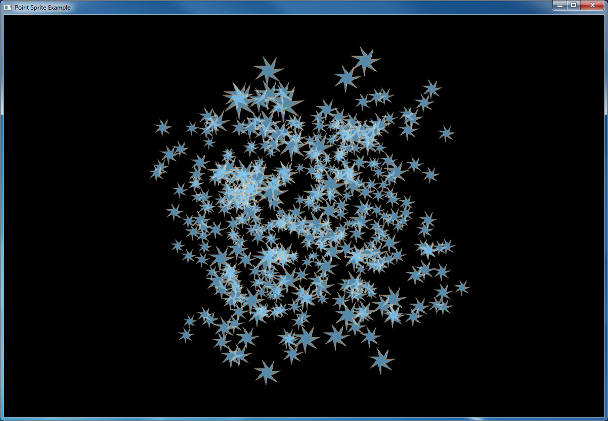
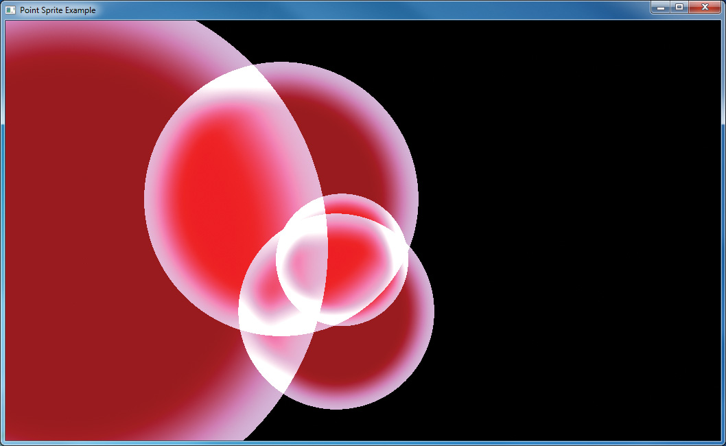
You are not limited to sourcing your point sprite data from a texture. Textures have a limited resolution, but gl_PointCoord can be quite precise. The shader shown in Example 6.31 demonstrates how you can analytically determine coverage in the fragment shader. This shader centers gl_PointCoord around the origin and then calculates the squared distance of the fragment from the center of the point sprite. If it’s greater than 0.25 (the square root of half the width of the sprite—or the radius of a circle that just fits inside it), the fragment is rejected using the discard keyword. Otherwise, we interpolate between two colors to produce the final output. This produces a perfect circle. Note that the same vertex shown in Example 6.29 is used for this example as well.
Example 6.31 Analytic Shape Fragment Shader
out vec4 color;
void main(void)
{
const vec4 color1 = vec4(0.6, 0.0, 0.0, 1.0);
const vec4 color2 = vec4(0.9, 0.7, 1.0, 0.0);
vec2 temp = gl_PointCoord - vec2(0.5);
float f = dot(temp, temp);
if (f > 0.25)
discard;
color = mix(color1, color2, smoothstep(0.1, 0.25, f));
}
Figure 6.21 shows the output of this example.
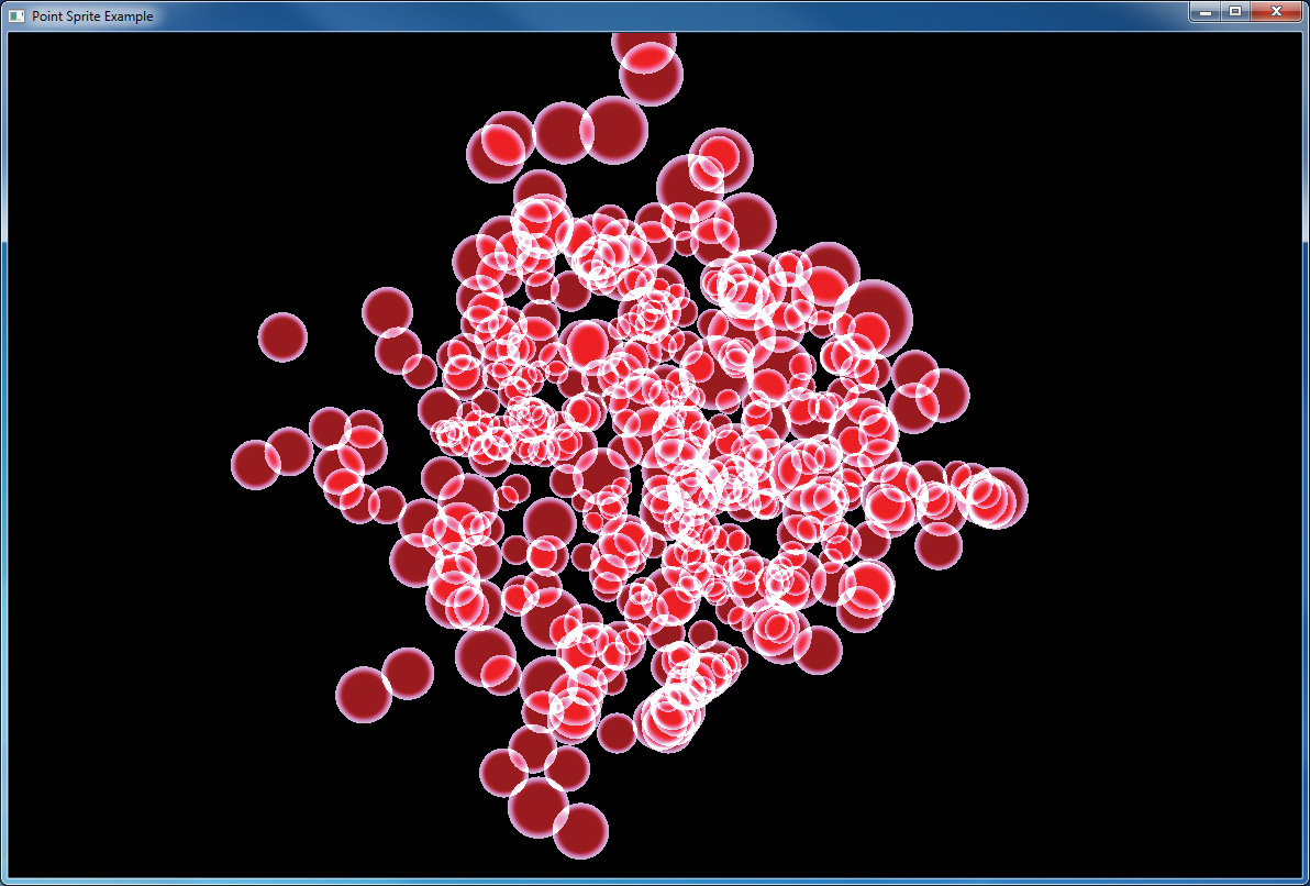
By increasing the size of the point sprite and reducing the number of points in the scene, it is possible to see the extremely smooth edges of the discs formed by the fragment shader, as shown in Figure 6.22.
Controlling the Appearance of Points
Various controls exist to allow the appearance of points to be tuned by your application. These parameters are set using glPointParameterf() or glPointParameteri().
The two parameters that you can change with glPointParameteri() or glPointParameterf() are the origin for gl_PointCoord (using GL_POINT_SPRITE_COORD_ORIGIN) the point fade threshold (using GL_POINT_FADE_THRESHOLD_SIZE). The point sprite coordinate origin controls whether gl_PointCoord.y increases from top down or bottom up in the fragment shader as points are rasterized. By default, the value of GL_POINT_SPRITE_COORD_ORIGIN is GL_UPPER_LEFT, meaning that it increases from top down. Note that this goes in the opposite direction from window coordinates, which have their origin in the lower right. By specifying GL_LOWER_LEFT for GL_POINT_SPRITE_COORD_ORIGIN you can make gl_PointCoord.y increase in the same direction as gl_FragCoord.y, which represents the fragment’s window coordinate.
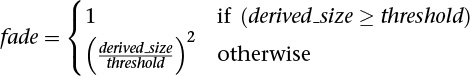
The other parameter that can be changed, GL_POINT_FADE_THRESHOLD, controls how points (and point sprites) are antialiased. When the size of a point falls below this threshold, OpenGL has the option to stop performing true antialiasing and instead fade the point into the background using blending. The default value of this parameter is 1.0, which means that if a point whose size is less than 1.0 is rasterized, rather than lighting a single sample within each fragment, OpenGL may light all the fragments in that sample but end up having the alpha component attenuated by the point fade factor, which is computed as follows:
Framebuffer Objects
Up to this point, all of our discussion regarding buffers has focused on the buffers provided by the windowing system, as you requested when you called glfwCreateWindow(). Although you can quite successfully use any technique with just those buffers, quite often, various operations require moving data between buffers superfluously. This is where framebuffer objects enter the picture. Using framebuffer objects, you can create our own framebuffers and use their attached renderbuffers to minimize data copies and optimize performance.
Framebuffer objects are quite useful for performing off-screen rendering, updating texture maps, and engaging in buffer ping-ponging (a data-transfer technique used in GPGPU).
The framebuffer that is provided by the windowing system is the only framebuffer that is available to the display system of your graphics server. That is, it is the only one you can see on your screen. It also places restrictions on the use of the buffers that were created when your window opened. By comparison, the framebuffers that your application creates cannot be displayed on your monitor; they support only off-screen rendering.
Another difference between window-system-provided framebuffers and framebuffers you create is that those managed by the window system allocate their buffers—color, depth, and stencil—when your window is created. When you create an application-managed framebuffer object, you need to create additional renderbuffers that you associate with the framebuffer objects you created. The buffers with the window-system-provided buffers can never be associated with an application-created framebuffer object, and vice versa.
To allocate an application-generated framebuffer object name, you need to call glCreateFramebuffers(), which will allocate an unused identifier for the framebuffer object and initialize it with the default framebuffer state.
Once a framebuffer object has been created with a call to glCreateFramebuffers(), it can be bound to the context by calling glBindFramebuffer(). glBindFramebuffer() operates in a similar manner to many of the other glBind*() routines you’ve seen in OpenGL. Calls to it will bind the provided framebuffer object name as the active one, and any rendering performed by OpenGL will be directed to the framebuffer object you specify. If no framebuffer object is bound, rendering is directed to the default framebuffer, which is usually the one provided by the operating system. The prototype of glBindFramebuffer() is
As with all of the other objects you have encountered in OpenGL, you can release an application-allocated framebuffer by calling glDeleteFramebuffers(). That function will mark the framebuffer object’s name as unallocated and release any resources associated with the framebuffer object.
For completeness, you can determine whether a particular unsigned integer is an application-allocated framebuffer object by calling glIsFramebuffer().
Once a framebuffer object is created, you still can’t do much with it, generally speaking. You need to provide a place for drawing to go and reading to come from; those places are called framebuffer attachments and can be textures or renderbuffers, which are a type of buffer you can attach to a framebuffer object.
Rendering to Texture Maps
Perhaps the most common use for a framebuffer object is to render directly into texture maps. You might do this to indicate changes in the texture for a surface (such as damage to a wall in a game) or to update values in a lookup table, if you’re doing GPGPU-like computations. In these cases, you bind a level of a texture map as a framebuffer attachment. After rendering, the texture map can be detached from the framebuffer object and used for subsequent rendering.
Note
Nothing prevents you from reading from a texture that is simultaneously bound as a framebuffer attachment for writing. In this scenario, called a framebuffer rendering loop, the results are undefined for both operations. That is, the values returned from sampling the bound texture map, as well as the values written into the texture level while bound, are undefined and likely incorrect.
Example 6.32 shows how to create a texture and attach a level of it to a framebuffer object for rendering.
Example 6.32 Attaching a Texture Level as a Framebuffer Attachment
GLsizei TexWidth, TexHeight;
GLuint framebuffer, texture;
void init()
{
// Create an empty texture
glCreateTextures(GL_TEXTURE_2D, 1, &texture);
glTextureStorage2D(texture,
1, GL_RGBA8,
TexWidth, TexHeight);
// Attach the texture to the framebuffer
glCreateFramebuffers(1, &framebuffer);
glNamedFramebufferTexture2D(framebuffer,
GL_COLOR_ATTACHMENT0, GL_TEXTURE_2D, texture, 0);
}
void
display()
{
// Render into the renderbuffer
glBindFramebuffer(GL_DRAW_FRAMEBUFFER, framebuffer);
glViewport(0, 0, TexWidth, TexHeight);
glClearColor(1.0, 0.0, 1.0, 1.0);
glClear(GL_COLOR_BUFFER_BIT | GL_DEPTH_BUFFER_BIT);
...
//Generate mipmaps of our texture
glGenerateTextureMipmap(texture);
// Bind to the window-system framebuffer, unbinding from
// the texture, which we can use to texture other objects
glBindFramebuffer(GL_FRAMEBUFFER, 0);
glViewport(0, 0, windowWidth, windowHeight);
glClearColor(0.0, 0.0, 1.0, 1.0);
glClear(GL_COLOR_BUFFER_BIT | GL_DEPTH_BUFFER_BIT);
// Render using the texture
glEnable(GL_TEXTURE_2D);
...
}
Discarding Rendered Data
As a rule of thumb, you should always clear the framebuffer before you begin rendering a frame. Modern GPUs implement compression and other techniques to improve performance, reduce memory bandwidth requirements, and so on. When you clear a framebuffer, the OpenGL implementation knows that it can discard any rendered data in the framebuffer and return it to a clean, compressed state if possible. However, what happens if you’re sure that you’re about to render over the whole framebuffer? It seems that clearing it would be a waste, as you are about to draw all over the cleared area. If you are certain that you are going to completely replace the contents of the framebuffer with new rendering, you can discard it with a call to glInvalidateNamedFramebufferData() or glInvalidateNamedFramebufferSubData(). Their prototypes are as follows:
Discarding the content of a framebuffer can be far more efficient than clearing it, depending on the OpenGL implementation. Furthermore, this can eliminate some expensive data copies in systems with more than one GPU. If, rather than discarding the content of the attachments of a framebuffer object, you wish to discard the content of a texture directly, you can call glInvalidateTexImage() or glInvalidateTexSubImage(). The prototypes for glInvalidateTexImage() and glInvalidateTexSubImage() are as follows:
Renderbuffers
Renderbuffers are effectively memory managed by OpenGL that contains formatted image data. The data that a renderbuffer holds takes meaning once it is attached to a framebuffer object, assuming that the format of the image buffer matches what OpenGL is expecting to render into (e.g., you can’t render colors into the depth buffer).
As with many other buffers in OpenGL, the process of allocating and deleting buffers is similar to what you’ve seen before. To create a new renderbuffer, you would call glCreateRenderbuffers().
Likewise, a call to glDeleteRenderbuffers() will release the storage associated with a renderbuffer.
Likewise, you can determine whether a name represents a valid renderbuffer by calling glIsRenderbuffer().
Similarly to the process of binding a framebuffer object so that you can modify its state, you call glBindRenderbuffer() to affect a renderbuffer’s creation and to modify the state associated with it, which includes the format of the image data that it contains.
Creating Renderbuffer Storage
When you first call create a new renderbuffer object with a call to glCreateRenderbuffers(), the OpenGL server creates a renderbuffer with all its state information set to the default values. In this configuration, no storage has been allocated to store image data. Before you can attach a renderbuffer to a framebuffer and render into it, you need to allocate storage and specify its image format. This is done by calling either glNamedRenderbufferStorage() or glNamedRenderbufferStorageMultisample().
void glNamedRenderbufferStorage(GLuint renderbuffer,
GLenum internalformat,
GLsizei width,
GLsizei height);
void glNamedRenderbufferStorageMultisample(GLuint renderbuffer,
GLsizei samples,
GLenum internalformat,
GLsizei width,
GLsizei height);
Example 6.33 Creating a 256 × 256 RGBA Color Renderbuffer
glCreateRenderbuffers(1, &color);
glNamedRenderbufferStorage(color, GL_RGBA, 256, 256);
Once you have created storage for your renderbuffer as shown in Example 6.33, you need to attach it to a framebuffer object before you can render into it.
Framebuffer Attachments
When you render, you can send the results of that rendering to a number of places:
• The color buffer to create an image or even multiple color buffers if you’re using multiple render targets (see “Writing to Multiple Renderbuffers Simultaneously” on page 363).
• The depth buffer to store occlusion information.
• The stencil buffer for storing per-pixel masks to control rendering. Each of those buffers represents a framebuffer attachment, to which you can attach suitable image buffers that you later render into or read from. The possible framebuffer attachment points are listed in Table 6.8.

Currently, there are two types of rendering surfaces you can associate with one of those attachments: renderbuffers and a level of a texture image.
We first discuss attaching a renderbuffer to a framebuffer object, which is done by calling glNamedFramebufferRenderbuffer().
In Example 6.34, we create and attach two renderbuffers: one for color and the other for depth. We then proceed to render and finally copy the results back to the window-system-provided framebuffer to display the results. You might use this technique to generate frames for a movie rendering off-screen, where you don’t have to worry about the visible framebuffer being corrupted by overlapping windows or someone resizing the window and interrupting rendering.
One important point to remember is that you might need to reset the viewport for each framebuffer before rendering, particularly if the size of your application-defined framebuffers differs from the window-system provided framebuffer.
Example 6.34 Attaching a Renderbuffer for Rendering
enum { Color, Depth, NumRenderbuffers };
GLuint framebuffer, renderbuffer[NumRenderbuffers]
void
init()
{
glCreateRenderbuffers(NumRenderbuffers, renderbuffer);
glNamedRenderbufferStorage(renderbuffer[color], GL_RGBA, 256, 256);
glNamedRenderbufferStorage(renderbuffer[Depth], GL_DEPTH_COMPONENT24,
256, 256);
glGenFramebuffers(1, &framebuffer);
glBindFramebuffer(GL_DRAW_FRAMEBUFFER, framebuffer);
glNamedFramebufferRenderbuffer(framebuffer, GL_COLOR_ATTACHMENT0,
GL_RENDERBUFFER, renderbuffer[Color]);
glNamedFramebufferRenderbuffer(framebuffer, GL_DEPTH_ATTACHMENT,
GL_RENDERBUFFER, renderbuffer[Depth]);
glEnable(GL_DEPTH_TEST);
}
void
display()
{
// Prepare to render into the renderbuffer
glBindFramebuffer(GL_DRAW_FRAMEBUFFER, framebuffer);
glViewport(0, 0, 256, 256);
// Render into renderbuffer
glClearColor(1.0, 0.0, 0.0, 1.0);
glClear(GL_COLOR_BUFFER_BIT | GL_DEPTH_BUFFER_BIT);
...
// Set up to read from the renderbuffer and draw to
// window-system framebuffer
glBindFramebuffer(GL_READ_FRAMEBUFFER, framebuffer);
glBindFramebuffer(GL_DRAW_FRAMEBUFFER, 0);
glViewport(0, 0, windowWidth, windowHeight);
glClearColor(0.0, 0.0, 1.0, 1.0);
glClear(GL_COLOR_BUFFER_BIT | GL_DEPTH_BUFFER_BIT);
/* Do the copy */
glBlitFramebuffer(0, 0, 255, 255, 0, 0, 255, 255,
GL_COLOR_BUFFER_BIT, GL_NEAREST);
glfwSwapBuffers(window);
}
Framebuffer Completeness
Given the myriad combinations between texture and buffer formats, and between framebuffer attachments, various situations can arise that prevent the completion of rendering when you are using application-defined framebuffer objects. After modifying the attachments to a framebuffer object, it’s best to check the framebuffer’s status by calling glCheckFramebufferStatus().
GLenum glCheckFramebufferStatus(GLenum target);
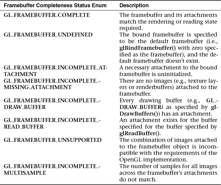
The errors representing the various violations of framebuffer configurations are listed in Table 6.9.
Of the listed errors, GL_FRAMEBUFFER_UNSUPPORTED is very implementation-dependent and may be the most complicated to debug.
Invalidating Framebuffers
Implementations of OpenGL (including OpenGL ES on mobile or embedded devices, most often) may work in limited-memory environments. Framebuffers have the potential of taking up considerable memory resources (particularly for multiple, multisampled color attachments and textures). OpenGL provides a mechanism to state that a region or all of a framebuffer is no longer needed and can be released. This operation is done with either glInvalidateSubFramebuffer() or glInvalidateFramebuffer().
Writing to Multiple Renderbuffers Simultaneously
One feature of using framebuffer objects with multiple renderbuffers (or textures) is the ability to write to multiple buffers from a fragment shader simultaneously, often called MRT (for multiple-render target) rendering. This is mostly a performance optimization, saving processing the same list of vertices multiple times and rasterizing the same primitives multiple times.
While this technique is used often in GPGPU, it can also be used when generating geometry and other information (like textures or normal map) that is written to different buffers during the same rendering pass. Enabling this technique requires setting up a framebuffer object with multiple color (and potentially depth and stencil) attachments and modifying the fragment shader. Having just discussed setting up multiple attachments, we focus on the fragment shader here.
As we’ve discussed, fragment shaders output values through their out variables. In order to specify the correspondence between out variables and framebuffer attachments, we simply need to use the layout qualifier to direct values to the right places. For instance, Example 6.35 demonstrates associating two variables with color attachment locations zero and one.
Example 6.35 Specifying layout Qualifiers for MRT Rendering
layout (location = 0) out vec4 color;
layout (location = 1) out vec4 normal;
If the attachments of the currently bound framebuffer don’t match those of the currently bound fragment shader, misdirected data (i.e., fragment shader data written to an attachment with nothing attached) accumulates in dark corners of the universe but is otherwise ignored.
Additionally, if you’re using dual-source blending (see “Dual-Source Blending” on page 367), with MRT rendering, you merely specify both the location and index options to the layout directive.
Using the layout qualifier within a shader is the preferred way to associate fragment shader outputs with framebuffer attachments, but if they are not specified, OpenGL will do the assignments during shader linking. You can direct the linker to make the appropriate associations by using the glBindFragDataLocation(), or glBindFragDataLocationIndexed() if you need to also specify the fragment index. Fragment shader bindings specified in the shader source will be used if specified, regardless of whether a location was specified using one of these functions.
After a program is linked, you can retrieve a fragment shader variable’s output location, and source index, if applicable, by calling glGetFragDataLocation() or glGetFragDataIndex().
Selecting Color Buffers for Writing and Reading
The results of a drawing or reading operation can go into or come from any of the color buffers:
• Front, back, front-left, back-left, front-right, or back-right for the default framebuffer
• Front or any renderbuffer attachment for a user-defined framebuffer object
You can choose an individual buffer to be the drawing or reading target. For drawing, you can also set the target to draw into more than one buffer at the same time. You use glDrawBuffer() or glDrawBuffers() to select the buffers to be written and glReadBuffer() to select the buffer as the source for glReadPixels().
void glDrawBuffer(GLenum mode);
void glDrawBuffers(GLsizei n, const GLenum *buffers);

When you are using double-buffering, you usually want to draw only in the back buffer (and swap the buffers when you’re finished drawing). In some situations, you might want to treat a double-buffered window as though it were single-buffered by calling glDrawBuffer(GL_FRONT_AND_BACK) to enable you to draw to both front and back buffers at the same time.
For selecting the read buffer, use glReadBuffer().
As we’ve seen, when a framebuffer object has multiple attachments, you can control various aspects of what happens with the renderbuffer at an attachment, like controlling the scissors box or blending. You use the commands glEnablei() and glDisablei() to control capabilities on a per-attachment granularity.
Dual-Source Blending
Advanced
Two of the blend factors already described in this chapters are the second source blending factors and are special in that they are driven by a second output in the fragment shader. These factors, GL_SRC1_COLOR and GL_SRC1_ALPHA, are produced in the fragment shader by writing to an output whose index is 1 (rather than the default 0). To create such an output, we use the index layout qualifier when declaring it in the fragment shader. Example 6.36 shows an example of such a declaration.
Example 6.36 Layout Qualifiers Specifying the Index of Fragment Shader Outputs
layout (location = 0, index = 0) out vec4 first_output;
layout (location = 0, index = 1) out vec4 second_output;
When calling glBlendFunc(), glBlendFunci(), glBlendFuncSeparate(), or glBlendFuncSeparatei(), the GL_SRC_COLOR, GL_SRC_ALPHA, GL_ONE_MINUS_SRC_COLOR, or GL_ONE_MINUS_SRC_ALPHA factors will cause the blending equation’s input to be taken from first_input. However, passing GL_SRC1_COLOR, GL_SRC1_ALPHA_GL_ONE_MINUS_SRC1_COLOR, or GL_ONE_MINUS_SRC1_ALPHA to these functions will cause the input to be taken from second_output. This allows some interesting blending equations to be built up by using combinations of the first and second sources in each of the source and destination blend factors.
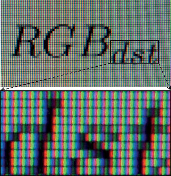
For example, setting the source factor to GL_SRC1_COLOR and the destination factor to GL_ONE_MINUS_SRC1_COLOR using one of the blending functions essentially allows a per-channel alpha to be created in the fragment shader. This type of functionality is especially useful when implementing subpixel accurate antialiasing techniques in the fragment shader. By taking the location of the red, green, and blue color elements in the pixels on the screen into account, coverage for each element can be generated in the fragment shader and be used to selectively light each color by a function of its coverage. Figure 6.23 shows a close-up picture of the red, green and blue picture elements in a liquid crystal computer monitor. The subpixels are clearly visible, although when viewed at normal distance, the display appears white. By lighting each of the red, green, and blue elements separately, very high-quality antialiasing can be implemented.
Another possible use is to set the source and destination factors in the blending equation to GL_ONE and GL_SRC1_COLOR. In this configuration, the first color output is added to the framebuffer’s content, while the second color output is used to attenuate the framebuffer’s content. The equation becomes
RGBdst = RGBsrc0 + RGBsrc1 ∗ RGBdst
This is a classic multiply-add operation and can be used for many purposes. For example, if you want to render a translucent object with a colored specular highlight, write the color of the object to second_output and the highlight color to first_output.
Dual-Source Blending and Multiple Fragment Shader Outputs
Because the second output from the fragment shader that is required to implement dual source blending may take from the resources available to produce outputs for multiple framebuffer attachments (draw buffers), there are special counting rules for dual-source blending. When dual-source blending is enabled—that is, when any of the factors specified to one of the glBlendFunc() functions is one of the tokens that includes SRC1—the total number of outputs available in the fragment shader may be reduced. To determine how many outputs may be used (and, consequently, how many framebuffer attachments may be active), query for the value of GL_MAX_DUAL_SOURCE_DRAW_BUFFERS. Note that the OpenGL specification requires only that GL_MAX_DUAL_SOURCE_DRAW_BUFFERS be at least one. If GL_MAX_DUAL_SOURCE_DRAW_BUFFERS is exactly one, this means that dual-source blending and multiple draw buffers are mutually exclusive and cannot be used together.
Chapter Summary
This chapter offered an overview of texturing in OpenGL. Applications of textures in computer graphics are wide-ranging and surprisingly complex. The best that can be done in a single chapter of a book is to scratch the surface and (we hope) convey to the reader the depth and usefulness of textures. Entire books could be written on advanced uses of textures. More information about textures can be found in subsequent chapters—including examples of how to draw into textures, use buffer textures, and store non-image data in textures.
Texture Redux
To use a texture in your program:
• Create a texture by
– Calling glCreateTextures() to create a new texture object
– Specifying the dimensions and format of the texture using glTextureStorage2D() or the appropriate function for texture type
– Placing data into the texture using glTextureSubImage2D() or the appropriate function for the texture type
• Access the texture in your shader by
– Declaring a uniform sampler in your shader to represent the texture
– Associating the sampler with the desired texture unit the binding layout qualifier
– Binding the texture object and optionally a sampler object to the correct texture unit by calling glBindTextureUnit()
– Reading from the texture in the shader using texture or one of other the built-in texture functions
To use a buffer object as a texture:
• Create a buffer texture by
– Creating a texture name using glCreateTextures() specifying the GL_TEXTURE_BUFFER texture target
• Create and initialize a buffer texture by
– Creating a new buffer using glCreateBuffers()
– Defining the storage for the buffer object using glNamedBufferStorage()
• Attach the buffer object’s data store to the texture by
– Calling glTextureBuffer() with the name of the initialized buffer object
Texture Best Practices
Here are some tips to ensure that you allow OpenGL to use your textures most efficiently, ensuring the best possible performance for your application. Some common pitfalls are enumerated here with some advice on how to avoid them.
Mipmaps
Create and initialize the mipmap chain for textures unless you have a good reason not to. Allowing the graphics hardware to use a lower-resolution mipmap when it needs to will not only improve the image quality of your program’s rendering, but also make more efficient use of the caches in the graphics processor. The texture cache is a small piece of memory that is used to store recently accessed texture data. The smaller the textures your application uses, the more of them will fit into the cache and the faster your application will run.
Integer Format Textures
Don’t forget to use an integer sampler (isampler2D, usampler3D, etc.) in your shader when your texture data is an unnormalized integer and you intend to use the integer values it contains directly in the shader. A common mistake is to create a floating-point sampler and use an integer internal format for the sampler, such as GL_RED_INTEGER. In this case, you may get undesired or even undefined results.