
Chapter 3. Drawing with OpenGL
Chapter Objectives
After reading this chapter, you will be able to:
• Identify all of the rendering primitives available in OpenGL.
• Initialize and populate data buffers for use in rendering geometry.
• Optimize rendering using advanced techniques like instanced rendering.
The primary use of OpenGL is to render graphics into a framebuffer. To accomplish this, complex objects are broken up into primitives—points, lines, and triangles that when drawn at high enough density give the appearance of 2D and 3D objects. OpenGL includes many functions for rendering such primitives. These functions allow you to describe the layout of primitives in memory, how many primitives to render and what form they take, and even to render many copies of the same set of primitives with one function call. These are arguably the most important functions in OpenGL, as without them, you wouldn’t be able to do much but clear the screen.
This chapter contains the following major sections:
• “OpenGL Graphics Primitives” describes the available graphics primitives in OpenGL that you can use in your renderings.
• “Data in OpenGL Buffers” explains the mechanics of working with data in OpenGL.
• “Vertex Specification” outlines how to use vertex data for rendering and how to process it using vertex shaders.
• “OpenGL Drawing Commands” includes how to use instancing to render multiple objects using the same vertex data efficiently.
OpenGL Graphics Primitives
OpenGL includes support for many primitive types. Eventually, they all get rendered as one of three types: points, lines, or triangles. Line and triangle types can be combined to form strips, loops (for lines), and fans (for triangles). Points, lines, and triangles are the native primitive types supported by most graphics hardware.1 Other primitive types are supported by OpenGL, including patches, which are used as inputs to the tessellator, and the adjacency primitives that are designed to be used as inputs to the geometry shader. Tessellation (and tessellation shaders) are introduced in Chapter 9, and geometry shaders are introduced in Chapter 10. The patch and adjacency primitive types are discussed in those chapters. In this section, we cover only the point, line, and triangle primitive types.
1. In terms of hardware support, this means that the graphics processor likely includes direct hardware support for rasterizing these types, of primitives. Other primitive types, such as patches and adjacency primitives, are never directly rasterized.
Points
Points are represented by a single vertex. The vertex represents a point in four-dimensional homogeneous coordinates. As such, a point really has no area, and so in OpenGL, it is really an analogue for a square region of the display (or draw buffer). When rendering points, OpenGL determines which pixels are covered by the point using a set of rules called rasterization rules. The rules for rasterizing a point in OpenGL are quite straightforward—a sample is considered covered by a point if it falls within a square centered on the point’s location in window coordinates. The side length of the square is equal to the point’s size, which is fixed state (set with glPointSize()), or the value written to the gl_PointSize built-in variable in the vertex, tessellation, or geometry shader. The value written to gl_PointSize in the shader is used only if GL_PROGRAM_POINT_SIZE is enabled; otherwise, it is ignored and the fixed state value set with glPointSize() is used.
The default point size is 1.0. Thus, when points are rendered, each vertex essentially becomes a single pixel on the screen (unless it’s clipped, of course). If the point size is increased (either with glPointSize() or by writing a value larger than 1.0 to gl_PointSize), each point vertex may end up lighting more than one pixel. For example, if the point size is 1.2 pixels and the point’s vertex lies exactly at a pixel center, only that pixel will be lit. However, if the point’s vertex lies exactly midway between two horizontally or vertically adjacent pixel centers, both of those pixels will be lit (i.e., two pixels will be lit). If the point’s vertex lies at the exact midpoint between four adjacent pixels, all four pixels will be lit, for a total of four pixels being lit for one point!
Point Sprites
When you render points with OpenGL, the fragment shader is run for every fragment in the point. Each point is essentially a square area of the screen, and each pixel can be shaded a different color. You can calculate that color analytically in the fragment shader or use a texture to shade the point. To assist in this, OpenGL fragment shaders include a special built-in variable called gl_PointCoord, which contains the coordinate within the point where the current fragment is located. gl_PointCoord is available only in the fragment shader (it doesn’t make much sense to include it in other shaders) and has a defined value only when rendering points. By simply using gl_PointCoord as a source for texture coordinates, bitmaps and textures can be used instead of a simple square block. Combined with alpha blending or with discarding fragments (using the discard keyword), it’s even possible to create point sprites with odd shapes.
Lines, Strips, and Loops
In OpenGL, the term line refers to a line segment, not the mathematician’s version that extends to infinity in both directions. Individual lines are therefore represented by pairs of vertices, one for each endpoint of the line. Lines can also be joined together to represent a connected series of line segments and optionally closed. The closed sequence is known as a line loop, whereas the open sequence (one that is not closed) is known as a line strip. As with points, lines technically have no area, so special rasterization rules are used to determine which pixels should be lit when a line segment is rasterized. The rule for line rasterization is known as the diamond exit rule. It is covered in some detail in the OpenGL specification. However, we attempt to paraphrase it here. When rasterizing a line running from point A to point B, a pixel should be lit if the line passes through the imaginary edge of a diamond shape drawn inside the pixel’s square area on the screen, unless that diamond contains point B (i.e., the end of the line is inside the diamond). That way, if another, second line is drawn from point B to point C, the pixel in which B resides is lit only once.
The diamond exit rule suffices for thin lines, but OpenGL allows you to specify wider sizes for lines using the glLineWidth() function (the equivalent of glPointSize() for lines).
There is no equivalent to gl_PointSize for lines. Lines are rendered at one fixed width until state is changed in OpenGL. When the line width is greater than 1, the line is simply replicated width times either horizontally or vertically. If the line is y-major (i.e., it extends further vertically than horizontally), it is replicated horizontally. If it is x-major, it is replicated vertically.
The OpenGL specification is somewhat liberal on how ends of lines are represented and how wide lines are rasterized when antialiasing is turned off. When antialiasing is turned on, lines are treated as rectangles aligned along the line, with width equal to the current line width.
Triangles, Strips, and Fans
Triangles are made up of collections of three vertices. When separate triangles are rendered, each triangle is independent of all others. A triangle is rendered by projecting each of the three vertices into screen space and forming three edges running between the edges. A sample is considered covered if it lies on the positive side of all of the half spaces formed by the lines between the vertices. If two triangles share an edge (and therefore a pair of vertices), no single sample can be considered inside both triangles. This is important because, although some variation in rasterization algorithm is allowed by the OpenGL specification, the rules governing pixels that lie along a shared edge are quite strict:
• No pixel on a shared edge between two triangles that together would cover the pixel should be left unlit.
• No pixel on a shared edge between two triangles should be lit by more than one of them.
This means that OpenGL will reliably rasterize meshes with shared edges without gaps between the triangles and without overdraw.2 This is important when rasterizing triangle strips or fans. When a triangle strip is rendered, the first three vertices form the first triangle; then each subsequent vertex forms another triangle along with the last two vertices of the previous triangle. This is illustrated in Figure 3.1
2. Overdraw is where the same pixel is lit more than once and can cause artifacts when blending is enabled, for example.

When rendering a triangle fan, the first vertex forms a shared point that is included in each subsequent triangle. Triangles are then formed using that shared point and the next two vertices. An arbitrarily complex convex polygon can be rendered as a triangle fan. Figure 3.2 shows the vertex layout of a triangle fan.

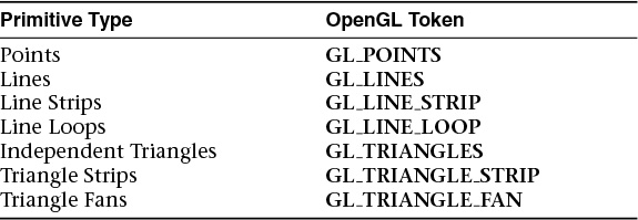
These primitive types are used by the drawing functions that will be introduced in the next section. They are represented by OpenGL tokens that are passed as arguments to functions used for rendering. Table 3.1 shows the mapping of primitive types to the OpenGL tokens used to represent them.
Rendering Polygons As Points, Outlines, or Solids
A polygon has two sides, front and back, and might be rendered differently depending on which side is facing the viewer. This allows you to have cutaway views of solid objects in which there is an obvious distinction between the parts that are inside and those that are outside. By default, both front and back faces are drawn in the same way. To change this, or to draw only outlines or vertices, use glPolygonMode().
Reversing and Culling Polygon Faces
By convention, polygons whose vertices appear in counterclockwise order on the screen are called front facing. You can construct the surface of any “reasonable” solid—a mathematician would call such a surface an orientable manifold (spheres, donuts, and teapots are orientable; Klein bottles and Möbius strips aren’t)—from polygons of consistent orientation. In other words, you can use all clockwise polygons or all counterclockwise polygons.
Suppose you’ve consistently described a model of an orientable surface but happen to have the clockwise orientation on the outside. You can swap what OpenGL considers the back face by using the function glFrontFace(), supplying the desired orientation for front-facing polygons.
In a completely enclosed surface constructed from opaque polygons with a consistent orientation, none of the back-facing polygons are ever visible—they’re always obscured by the front-facing polygons. If you are outside this surface, you might enable culling to discard polygons that OpenGL determines are back-facing. Similarly, if you are inside the object, only back-facing polygons are visible. To instruct OpenGL to discard front-or back-facing polygons, use the command glCullFace() and enable culling with glEnable().
Advanced
In more technical terms, deciding whether a face of a polygon is front- or back-facing depends on the sign of the polygon’s area computed in window coordinates. One way to compute this area is

where xi and yi are the x and y window coordinates of the ith vertex of the n-vertex polygon and where i ⊕ 1 is shorthand for (i + 1) mod n, where mod is the modulus operator.
Assuming that GL_CCW has been specified, if a > 0, the polygon corresponding to that vertex is considered to be front-facing; otherwise, it’s back-facing. If GL_CW is specified and if a < 0, the corresponding polygon is front-facing; otherwise, it’s back-facing.
Data in OpenGL Buffers
Almost everything you will ever do with OpenGL will involve buffers full of data. Buffers in OpenGL are represented as buffer objects. You’ve already had a brief introduction to buffer objects in Chapter 1. However, in this section we dig a little deeper into the specifics of how buffer objects are used; ways to create, manage, and destroy them; and the best practices associated with buffer objects.
Creating and Allocating Buffers
As with many things in OpenGL, buffer objects are named using GLuint values. Values are reserved using the glCreateBuffers() command. This function has already been described in Chapter 1, but we include the prototype here again for handy reference.
After calling glCreateBuffers(), you will have an array of buffer object names in buffers. The buffer objects themselves have been created but don’t have any storage associated with them. You will need to allocate storage for each buffer object by calling glNamedBufferStorage() on it. Once it has storage, you can bind3 it to one of the targets listed in Table 3.2.
3. It’s fine to bind the buffer before allocating storage for it, but it’s not going to be useful for much until the storage is allocated.
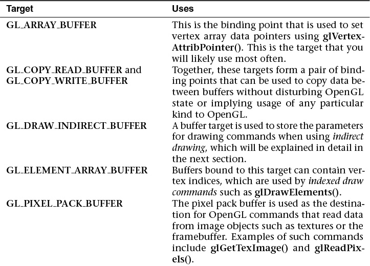
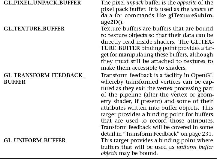
A buffer made ready for use by binding one of the names reserved by a call to glCreateBuffers() to one of the targets in Table 3.2 using glBindBuffer(). As with glCreateBuffers(), glBindBuffer() was introduced in Chapter 1, but we include its prototype here again for completeness.
Right, so we now have a buffer object bound to one of the targets listed in Table 3.2; now what? The default state of a newly created buffer object is a buffer with no data in it. Before it can be used productively, we must put some data into it.
Getting Data into and out of Buffers
There are many ways to get data into and out of buffers in OpenGL. These range from explicitly providing the data, to replacing parts of the data in a buffer object with new data, to generating the data with OpenGL and recording it into the buffer object. The simplest way to get data into a buffer object is to load data into the buffer at time of allocation. This is accomplished through the use of the glNamedBufferStorage() function. Here’s the prototype of glNamedBufferStorage() again.
Possibly the most important parameter to glNamedBufferStorage() is the flags parameter. flags is a bitwise combination of the flags shown in Table 3.3.
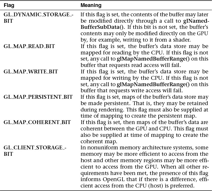
Accurate specification of the flags parameter is important to achieve optimal performance and correct behavior. This parameter conveys useful information to OpenGL about how you plan to use the buffer.
Initializing Part of a Buffer
Suppose you have an array containing some vertex data, another containing some color information, and yet another containing texture coordinates or some other data. You’d like to pack the data back to back into one big buffer object so that OpenGL can use it. The arrays may or may not be contiguous in memory, so you can’t simply supply all of the data when you call glNamedBufferStorage() to upload all of it in one go. Further, if you use glNamedBufferStorage() to upload, say, the vertex data first, the buffer will be sized to match the vertex data, and there won’t be room for the color or texture coordinate information. That’s where glNamedBufferSubData() comes in.
By using a combination of glNamedBufferStorage() and glNamedBufferSubData(), we can allocate and initialize a buffer object and upload data into several separate sections of it. An example is shown in Example 3.1.
Example 3.1 Initializing a Buffer Object with glNamedBufferStorage()
// Vertex positions
static const GLfloat positions[] =
{
-1.0f, -1.0f, 0.0f, 1.0f,
1.0f, -1.0f, 0.0f, 1.0f,
1.0f, 1.0f, 0.0f, 1.0f,
-1.0f, 1.0f, 0.0f, 1.0f
};
// Vertex colors
static const GLfloat colors[] =
{
1.0f, 0.0f, 0.0f, 0.0f,
1.0f, 0.0f, 0.0f, 0.0f,
1.0f, 1.0f, 1.0f, 1.0f,
};
// The buffer object
GLuint buffer;
// Create a new buffer object.
glCreateBuffers(1, &buffer);
// Allocate space for it (sizeof(positions) + sizeof(colors)).
glNamedBufferStorage(buffer, // target
sizeof(positions) + sizeof(colors), // total size
nullptr, // no data
GL_DYNAMIC_STORAGE_BIT); // flags
// Put 'positions' at offset zero in the buffer.
glNamedBufferSubData(buffer, // target
0, // offset
sizeof(positions), // size
positions); // data
// Put 'colors' at an offset in the buffer equal to the filled size of
// the buffer so far - i.e., sizeof(positions).
glNamedBufferSubData(buffer, // target
sizeof(positions), // offset
sizeof(colors), // size
colors); // data
// Now 'positions' is at offset 0 and 'colors' is directly after it
// in the same buffer.
If you simply wish to clear a buffer object’s data store to a known value, you can use either the glClearNamedBufferData() or the glClearNamedBufferSubData() function. Their prototypes are as follows:
Using glClearNamedBufferData() or glClearNamedBufferSubData() allows you to initialize the data store of a buffer object without necessarily reserving and clearing a region of system memory to do it.
Data can also be copied between buffer objects using the glCopyNamedBufferSubData() function. Rather than assembling chunks of data in one large buffer object using glNamedBufferSubData(), it is possible to upload the data into separate buffers using glNamedBufferStorage() and then copy from those buffers into the larger buffer using glCopyNamedBufferSubData(). You may be able to overlap these copies by allocating a set of staging buffers and rotating through them such that data that’s being overwritten isn’t simultaneously in use.
The prototype of glCopyNamedBufferSubData() is as follows:
While glCopyNamedBufferSubData() can be used to copy data between buffers bound to any two targets, the targets GL_COPY_READ_BUFFER and GL_COPY_WRITE_BUFFER are provided specifically for this purpose. Neither target is used for anything else by OpenGL, and so you can safely bind buffers to them for the purposes of copying or staging data without disturbing OpenGL state or needing to keep track of what was bound to the target before your copy.
Reading the Contents of a Buffer
Data can be read back from a buffer object in a couple of different ways. The first is to use the glGetBufferSubData() function. This function reads data from the buffer object bound to one of the targets and places it into a chunk of memory owned by your applications. The prototype of glGetNamedBufferSubData() is as follows:
glGetNamedBufferSubData() is useful when you have generated data using OpenGL and wish to retrieve it. Examples include using transform feedback to process vertices using a GPU, or reading framebuffer or texture data into a Pixel Buffer Object. Both of these topics will be covered later. Of course, it’s also possible to use glGetBufferSubData() to simply read back data that you previously put into the buffer object.
Accessing the Content of Buffers
The issue with all of the functions covered in this section so far (glNamedBufferSubData(), glCopyNamedBufferSubData(), and glGetNamedBufferSubData()) is that they all cause OpenGL to make a copy of your data. glNamedBufferSubData() copies data from your application’s memory into memory owned by OpenGL. Meanwhile, glCopyNamedBufferSubData() may be used to copy data from one buffer to another or between different locations in a single buffer. glGetNamedBufferSubData() copies data from a buffer object into memory provided by your application. Depending on the hardware configuration, it’s very possible that the memory owned by OpenGL would be accessible to your application if only you had a pointer to it. Well, you can get that pointer using glMapBuffer().
When you call glMapBuffer(), the function returns a pointer to memory that represents the data store of the buffer object attached to target. Note that this memory represents only this buffer; it is not necessarily the memory that the graphics processor will use. The access parameter specifies how the application intends to use the memory once it is mapped. It must be one of the tokens shown in Table 3.4.
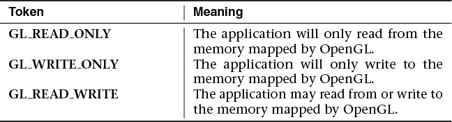
If glMapBuffer() fails to map the buffer object’s data store, it returns NULL. The access parameter forms a contract between you and OpenGL that specifies how you will access the memory. If you violate that contract, bad things will happen, which may include ignoring writes to the buffer, corrupting your data, or even crashing your program.4
4. The unfortunate thing is that so many applications do violate this contract that most OpenGL implementations will assume you don’t know what you’re doing and will treat all calls to glMapBuffer() as if you specified GL_READ_WRITE as the access parameter, just so these other applications will work.
Note
When you map a buffer whose data store is in memory that will not be accessible to your application, OpenGL may need to move the data around so that when you use the pointer it gives you, you get what you expect. Likewise, when you’re done with the data and have modified it, OpenGL may need to move it back to a place where the graphics processor can see it. This can be expensive in terms of performance, so great care should be taken when doing this.
When the buffer is mapped with the GL_READ_ONLY or GL_READ_WRITE access mode, the data that was in the buffer object becomes visible to your application. You can read it back, write it to a file, and even modify it in place (so long as you used GL_READ_WRITE as the access mode). If access is GL_READ_WRITE or GL_WRITE_ONLY, you can write data into memory using the pointer OpenGL gave you. Once you are done using the data or writing data into the buffer object, you must unmap it using glUnmapNamedBuffer(), whose prototype is as follows:
When you unmap the buffer, any data you wrote into the memory given to you by OpenGL becomes visible in the buffer object. This means that you can place data into buffer objects by allocating space for them using glNamedBufferStorage() and passing NULL as the data parameter, mapping them, writing data into them directly, and then unmapping them again. Example 3.2 contains an example of loading the contents of a file into a buffer object.
Example 3.2 Initializing a Buffer Object with glMapBuffer()
GLuint buffer;
FILE * f;
size_t filesize;
// Open a file and find its size
f = fopen("data.dat", "rb");
fseek(f, 0, SEEK_END);
filesize = ftell(f);
fseek(f, 0, SEEK_SET);
// Create a buffer by generating a name and binding it to a buffer
// binding point - GL_COPY_WRITE_BUFFER here (because the binding means
// nothing in this example).
glGenBuffers(1, &buffer);
glBindBuffer(GL_COPY_WRITE_BUFFER, buffer);
// Allocate the data store for the buffer by passing NULL for the
// data parameter.
glBufferData(GL_COPY_WRITE_BUFFER, (GLsizei)filesize, NULL,
GL_STATIC_DRAW);
// Map the buffer...
void * data = glMapBuffer(GL_COPY_WRITE_BUFFER, GL_WRITE_ONLY);
// Read the file into the buffer.
fread(data, 1, filesize, f);
// Okay, done, unmap the buffer and close the file.
glUnmapBuffer(GL_COPY_WRITE_BUFFER);
fclose(f);
In Example 3.2, the entire contents of a file are read into a buffer object in a single operation. The buffer object is created and allocated to the same size as the file. Once the buffer is mapped, the file can be read directly into the buffer object’s data store. No copies are made by the application, and if the data store is visible to both the application and the graphics processor, no copies will be made by OpenGL.
There may be significant performance advantages to initializing buffer objects in this manner. The logic is this: When you call glNamedBufferStorage() or glNamedBufferSubData(), once those functions return, you are free to do whatever you want with the memory you gave them—free it, use it for something else, it doesn’t matter. This means that those functions must be done with that memory by the time they return, and so they need to make a copy of your data. However, when you call glMapNamedBufferRange(), the pointer you get points at memory owned by OpenGL. When you call glUnmapNamedBuffer(), OpenGL still owns that memory; it’s the application that has to be done with it. This means that if the data needs to be moved or copied, OpenGL can start that process when you call glUnmapNamedBuffer() and return immediately, content in the knowledge that it can finish the operation at its leisure without your application interfering in any way. Thus, the copy that OpenGL needs to perform can overlap whatever your application does next (making more buffers, reading more files, and so on). If it doesn’t need to make a copy, great! The unmap operation essentially becomes free in that case.
Asynchronous and Explicit Mapping
To address many of the issues involved with mapping buffers using glMapBuffer() (such as applications incorrectly specifying the access parameter or always using GL_READ_WRITE), glMapNamedBufferRange() uses flags to specify access more precisely. The prototype for glMapNamedBufferRange() is as follows:
For glMapNamedBufferRange(), access is a bitfield that must contain one or both of the GL_MAP_READ_BIT and the GL_MAP_WRITE_BIT indicating whether the application plans to read from the mapped data store, write to it, or do both. In addition, access may contain one or more of the flags shown in Table 3.5.
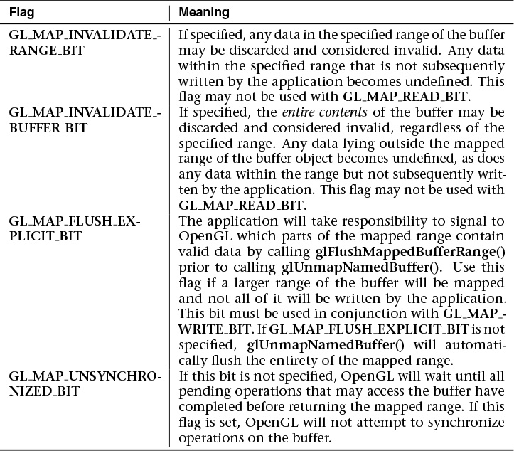
As you can see from the flags listed in Table 3.5, the command provides a significant level of control over how OpenGL uses the data in the buffer and how it synchronizes operations that may access that data.
When you specify that you want to invalidate the data in the buffer object by specifying either the GL_MAP_INVALIDATE_RANGE_BIT or GL_MAP_INVALIDATE_BUFFER_BIT, this indicates to OpenGL that it is free to dispose of any previously stored data in the buffer object. Either flag can be set only if you also specify that you’re going to write to the buffer by also setting the GL_MAP_WRITE_BIT flag. If you specify GL_MAP_INVALIDATE_RANGE_BIT, it indicates that you will update the entire range (or at least all the parts of it that you care about). If you set the GL_MAP_INVALIDATE_BUFFER_BIT, it means that you don’t care what ends up in the parts of the buffer that you didn’t map or you’re planning to update the rest of the buffer with subsequent maps.5 When OpenGL is allowed to throw away the rest of the buffer’s data, it doesn’t have to make any effort to merge your modified data back into the rest of the original buffer. It’s probably a good idea to use GL_MAP_INVALIDATE_BUFFER_BIT for the first section of the buffer that you map and GL_MAP_INVALIDATE_RANGE_BIT for the rest of the buffer.
5. Don’t specify the GL_MAP_INVALIDATE_BUFFER_BIT for every section; otherwise, only the last section you mapped will have valid data in it!
The GL_MAP_UNSYNCHRONIZED_BIT flag is used to disengage OpenGL’s automatic synchronization between data transfer and use. Without this bit, OpenGL will finish up any in-flight commands that might be using the buffer object. This can stall the OpenGL pipeline, causing a bubble and a loss of performance. If you can guarantee that all pending commands will be complete before you actually modify the contents of the buffer (but not necessarily before you call glMapNamedBufferRange()) through a method such as calling glFinish() or using a sync object (which are described in “Atomic Operations and Synchronization” on page 591 in Chapter 11), OpenGL doesn’t need to do this synchronization for you.
Finally, the GL_MAP_FLUSH_EXPLICIT_BIT flag indicates that the application will take on the responsibility of letting OpenGL know which parts of the buffer it has modified before calling glUnmapNamedBuffer(). It does this through a call to glFlushMappedNamedBufferRange(), whose prototype is as follows:
It is possible to call glFlushMappedNamedBufferRange() multiple times on separate or even overlapping ranges of a mapped buffer object. The range of the buffer object specified by offset and length must lie within the range of the buffer object that has been mapped, and that range must have been mapped by a call to glMapNamedBufferRange() with access including the GL_MAP_FLUSH_EXPLICIT_BIT flag set. When this call is made, OpenGL assumes that you’re done modifying the specified range of the mapped buffer object and that it can begin any operations it needs to perform in order to make that data usable such as copying it to graphics processor visible memory, or flushing, or invalidating data caches. It can do these things even though some or all of the buffer is still mapped. This is a useful way to parallelize OpenGL with other operations that your application might perform. For example, if you need to load a very large piece of data from a file into a buffer, map a range of the buffer large enough to hold the whole file, then read chunks of the file, and after each chunk call glFlushMappedNamedBufferRange(). OpenGL will operate in parallel to your application, reading more data from the file for the next chunk.
By combining these flags in various ways, it is possible to optimize data transfer between the application and OpenGL or to use advanced techniques such as multithreading and asynchronous file operations.
Discarding Buffer Data
Advanced
When you are done with the data in a buffer, it can be advantageous to tell OpenGL that you don’t plan to use it anymore. For example, consider the case where you write data into a buffer using transform feedback and then draw using that data. If that drawing command is the last one that is going to access the data, you can tell OpenGL that it is free to discard the data and use the memory for something else. This allows an OpenGL implementation to make optimizations such as tightly packing memory allocations or avoiding expensive copies in systems with more than one GPU.
To discard some or all of the data in a buffer object, you can call glInvalidateBufferData() or glInvalidateBufferSubData(), respectively. The prototypes of these functions are as follows:
Vertex Specification
Now that you have data in buffers, and you know how to write a basic vertex shader, it’s time to hook the data up to the shader. You’ve already read about vertex array objects, which contain information about where data is located and how it is laid out, and functions like glVertexAttribPointer(). It’s time to take a deeper dive into vertex specifications, other variants of glVertexAttribPointer(), and how to specify data for vertex attributes that aren’t floating-point or aren’t enabled.
VertexAttribPointer in Depth
The glVertexAttribPointer() command was briefly introduced in Chapter 1. The prototype is as follows:
The state set by glVertexAttribPointer() is stored in the currently bound vertex array object (VAO). size is the number of elements in the attribute’s vector (1, 2, 3, or 4), or the special token GL_BGRA, which should be specified when packed vertex data is used. The type parameter is a token that specifies the type of the data that is contained in the buffer object. Table 3.6 describes the token names that may be specified for type and the OpenGL data type that they correspond to:
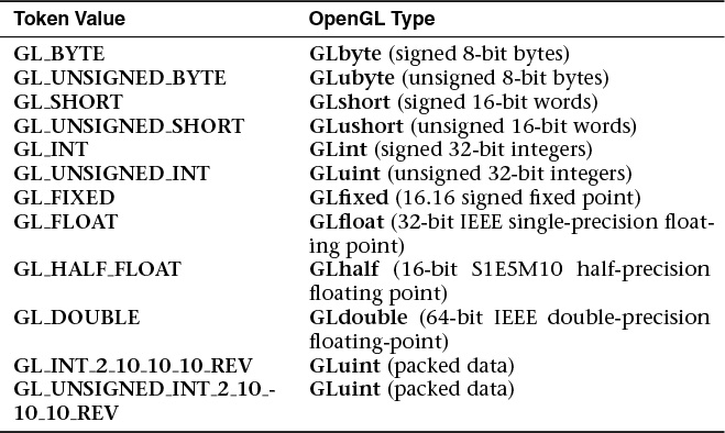
Note that while integer types such as GL_SHORT or GL_UNSIGNED_INT can be passed to the type argument, this tells OpenGL only what data type is stored in memory in the buffer object. OpenGL will convert this data to floating-point in order to load it into floating-point vertex attributes. The way this conversion is performed is controlled by the normalize parameter. When normalize is GL_FALSE, integer data is simply typecast into floating-point format before being passed to the vertex shader. This means that if you place the integer value 4 into a buffer and use the GL_INT token for the type when normalize is GL_FALSE, the value 4.0 will be placed into the shader. When normalize is GL_TRUE, the data is normalized before being passed to the vertex shader. To do this, OpenGL divides each element by a fixed constant that depends on the incoming data type. When the data type is signed, the following formula is used:
If the data type is unsigned, the following formula is used:
In both cases, f is the resulting floating-point value, c is the incoming integer component, and b is the number of bits in the data type (i.e., 8 for GL_UNSIGNED_BYTE, 16 for GL_SHORT, and so on). Note that unsigned data types are also scaled and biased before being divided by the type-dependent constant. To return to our example of putting 4 into an integer vertex attribute, we get
which works out to about 0.000000009313—a pretty small number!
Integer Vertex Attributes
If you are familiar with the way floating-point numbers work, you’ll also realize that precision is lost as numbers become very large, and so the full range of integer values cannot be passed into a vertex shader using floating-point attributes. For this reason, we have integer vertex attributes. These are represented in vertex shaders by the int, ivec2, ivec3, or ivec4 types or their unsigned counterparts—uint, uvec2, uvec3, and uvec4.
A second vertex-attribute function is needed in order to pass raw integers into these vertex attributes, one that doesn’t automatically convert everything to floating-point. This is glVertexAttribIPointer()—the I stands for integer.
Notice that the parameters to glVertexAttribIPointer() are identical to the parameters to glVertexAttribPointer() except for the omission of the normalize parameter. normalize is missing because it’s not relevant to integer vertex attributes. Only the integer data type tokens GL_BYTE, GL_UNSIGNED_BYTE, GL_SHORT, GL_UNSIGNED_SHORT, GL_INT, and GL_UNSIGNED_INT may be used for the type parameter.
Double-Precision Vertex Attributes
The third variant of glVertexAttribPointer() is glVertexAttribLPointer(). Here, the L stands for “long.” This version of the function is specifically for loading attribute data into 64-bit double-precision floating-point vertex attributes.
Again, notice the lack of the normalize parameter. In glVertexAttribPointer(), normalize was used only for integer data types that aren’t legal here, and so the parameter is not needed. If GL_DOUBLE is used with glVertexAttribPointer(), the data is automatically down-converted to 32-bit single-precision floating-point representation before being passed to the vertex shader—even if the target vertex attribute was declared using one of the double-precision types double, dvec2, dvec3, or dvec4, or one of the double-precision matrix types such as dmat4. However, with glVertexAttribLPointer(), the full precision of the input data is kept and passed to the vertex shader.
Packed Data Formats for Vertex Attributes
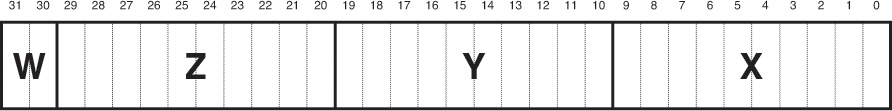
Going back to the glVertexAttribPointer() command, you will notice that the allowed values for the size parameter are 1, 2, 3, 4, and the special token GL_BGRA. Also, the type parameter may take one of the special values GL_INT_2_10_10_10_REV or GL_UNSIGNED_INT_2_10_10_10_REV, both of which correspond to the GLuint data type. These special tokens are used to represent packed data that can be consumed by OpenGL. The GL_INT_2_10_10_10_REV and GL_UNSIGNED_INT_2_10_10_10_REV tokens represent four-component data represented as ten bits for each of the first three components and two for the last, packed in reverse order into a single 32-bit quantity (a GLuint). GL_BGRA could just have easily been called GL_ZYXW.6 Looking at the data layout within the 32-bit word, you would see the bits divided up as shown in Figure 3.3.
6. Not a valid OpenGL token, just to be clear.

In Figure 3.3, the elements of the vertex are packed into a single 32-bit integer in the order w, x, y, z, which when reversed is z, y, x, w, or b, g, r, a when using color conventions. In Figure 3.4, the coordinates are packed in the order w, z, y, x, which reversed and written in color conventions is r, g, b, a.
Vertex data may be specified only in the first of these two formats by using the GL_INT_2_10_10_10_REV or GL_UNSIGNED_INT_2_10_10_10_REV tokens. When one of these tokens is used as the type parameter to glVertexAttribPointer(), each vertex consumes one 32-bit word in the vertex array. The word is unpacked into its components and then optionally normalized (depending on the value of the normalize parameter before being loaded into the appropriate vertex attribute. This data arrangement is particularly well suited to normals or other types of attributes that can benefit from the additional precision afforded by the 10-bit components but perhaps don’t require the full precision offered by half-float data (which would take 16 bits per component). This allows the conservation of memory space and bandwidth, which helps improve performance.
Static Vertex-Attribute Specification
Remember from Chapter 1 where you were introduced to glEnableVertexAttribArray() and glDisableVertexAttribArray(). These functions are used to tell OpenGL which vertex attributes are backed by vertex buffers. Before OpenGL will read any data from your vertex buffers, you must enable the corresponding vertex attribute arrays with glEnableVertexAttribArray(). You may wonder what happens if you don’t enable the attribute array for one of your vertex attributes. In that case, the static vertex attribute is used. The static vertex attribute for each vertex is the default value that will be used for the attribute when there is no enabled attribute array for it. For example, imagine you had a vertex shader that would read the vertex color from one of the vertex attributes. Now suppose that all of the vertices in a particular mesh or part of that mesh had the same color. It would be a waste of memory and potentially of performance to fill a buffer full of that constant value for all the vertices in the mesh. Instead, you can just disable the vertex attribute array and use the static vertex attribute to specify color for all of the vertices.
The static vertex attribute for each attribute may be specified using one of glVertexAttrib*() functions. When the vertex attribute is declared as a floating-point quantity in the vertex shader (i.e., it is of type float, vec2, vec3, vec4, or one of the floating-point matrix types such as mat4), the following glVertexAttrib*() commands can be used to set its value.
All of these functions implicitly convert the supplied parameters to floating-point before passing them to the vertex shader (unless they’re already floating-point). This conversion is a simple typecast. That is, the values are converted exactly as specified as though they had been specified in a buffer and associated with a vertex attribute by calling glVertexAttribPointer() with the normalize parameter set to GL_FALSE. For the integer variants of the functions, versions exist that normalize the parameters to the range [0, 1] or [–1, 1] depending on whether the parameters are signed or unsigned. These are
Even with these commands, the parameters are still converted to floating-point before being passed to the vertex shader. Thus, they are suitable only for setting the static values of attributes declared with one of the single-precision floating-point data types. If you have vertex attributes that are declared as integers or double-precision floating-point variables, you should use one of the following functions:
Furthermore, if you have vertex attributes that are declared as one of the double-precision floating-point types, you should use one of the L variants of glVertexAttrib*(), which are
Both the glVertexAttribI*() and glVertexAttribL*() variants of glVertexAttrib*() pass their parameters through to the underlying vertex attribute just as the I versions of glVertexAttribIPointer() do.
If you use one of the glVertexAttrib*() functions with fewer components than there are in the underlying vertex attribute (e.g., you use glVertexAttrib*() 2f to set the value of a vertex attribute declared as a vec4), default values are filled in for the missing components. For w, 1.0 is used as the default value, and for y and z, 0.0 is used.7 If you use a function that takes more components than are present in the vertex attribute in the shader, the additional components are simply discarded.
7. The lack of a default for x is intentional—you can’t specify values for y, z, or w without also specifying a value for x.
Note
The static vertex attribute values are stored in the current VAO, not the program object. That means that if the current vertex shader has, for example, a vec3 input and you use glVertexAttrib*() 4fv to specify a four-component vector for that attribute, the fourth component will be ignored but still stored. If you change the vertex shader to one that has a vec4 input at that attribute location, the fourth component specified earlier will appear in that attribute’s w component.
OpenGL Drawing Commands
Most OpenGL drawing commands start with the word Draw.8 The drawing commands are roughly broken into two subsets: indexed and nonindexed draws. Indexed draws use an array of indices stored in a buffer object bound to the GL_ELEMENT_ARRAY_BUFFER binding, which is used to indirectly index into the enabled vertex arrays. On the other hand, nonindexed draws do not use the GL_ELEMENT_ARRAY_BUFFER at all and simply read the vertex data sequentially. The most basic nonindexed drawing command in OpenGL is glDrawArrays().
8. In fact, the only two commands in OpenGL that start with Draw but don’t draw anything are glDrawBuffer() and glDrawBuffers().
Similarly, the most basic indexed drawing command is glDrawElements().
Each of these functions causes vertices to be read from the enabled vertex-attribute arrays and used to construct primitives of the type specified by mode. Vertex-attribute arrays are enabled using glEnableVertexAttribArray() as described in Chapter 1. glDrawArrays() just uses the vertices in the buffer objects associated with the enabled vertex attributes in the order they appear. glDrawElements() uses the indices in the element array buffer to index into the vertex attribute arrays. Each of the more complex OpenGL drawing functions essentially builds functionality on top of these two functions. For example, glDrawElementsBaseVertex() allows the indices in the element array buffer to be offset by a fixed amount.
glDrawElementsBaseVertex() allows the indices in the element array buffer to be interpreted relative to some base index. For example, multiple versions of a model (say, frames of an animation) can be stored in a single set of vertex buffers at different offsets within the buffer. glDrawElementsBaseVertex() can then be used to draw any frame of that animation by simply specifying the first index that corresponds to that frame. The same set of indices can be used to reference every frame.
Another command that behaves similarly to glDrawElements() is glDrawRangeElements().
Various combinations of functionality are available through even more advanced commands. For example, glDrawRangeElementsBaseVertex() combines the features of glDrawElementsBaseVertex() with the contractual arrangement of glDrawRangeElements().
Instanced versions of both of these functions are also available. Instancing will be covered in “Instanced Rendering” on page 137. The instancing commands include glDrawArraysInstanced(), glDrawElementsInstanced(), and even glDrawElementsInstancedBaseVertex(). Finally, there are two commands that take their parameters not from your program directly, but from a buffer object. These are the draw-indirect functions, and to use them, a buffer object must be bound to the GL_DRAW_INDIRECT_BUFFER binding. The first is the indirect version of glDrawArrays(), glDrawArraysIndirect().
In glDrawArraysIndirect(), the parameters for the actual draw command are taken from a structure stored at offset indirect into the draw indirect buffer. The structure’s declaration in C is presented in Example 3.3.
Example 3.3 Declaration of the DrawArraysIndirectCommand Structure
typedef struct DrawArraysIndirectCommand_t
{
GLuint count;
GLuint primCount;
GLuint first;
GLuint baseInstance;
} DrawArraysIndirectCommand;
The fields of the DrawArraysIndirectCommand structure are interpreted as if they were parameters to a call to glDrawArraysInstanced(). first and count are passed directly to the internal function. The primCount field is the instance count, and the baseInstance field becomes the baseInstance offset to any instanced vertex attributes. (Don’t worry; the instanced rendering commands will be described shortly.)
The indirect version of glDrawElements() is glDrawElementsIndirect() and its prototype is
As with glDrawArraysIndirect(), the parameters for the draw command in glDrawElementsIndirect() come from a structure stored at offset indirect stored in the element array buffer. The structure’s declaration in C is presented in Example 3.4.
Example 3.4 Declaration of the DrawElementsIndirectCommand Structure
typedef struct DrawElementsIndirectCommand_t
{
GLuint count;
GLuint primCount;
GLuint firstIndex;
GLuint baseVertex;
GLuint baseInstance;
} DrawElementsIndirectCommand;
As with the DrawArraysIndirectCommand structure, the fields of the DrawElementsIndirectCommand structure are also interpreted as calls to the glDrawElementsInstancedBaseVertex() command. count and baseVertex are passed directly to the internal function. As in glDrawArraysIndirect(), primCount is the instance count. firstVertex is used, along with the size of the indices implied by the type parameter to calculate the value of indices that would have been passed to glDrawElementsInstancedBaseVertex(). Again, baseInstance becomes the instance offset to any instanced vertex attributes used by the resulting drawing commands.
Now we come to the drawing commands that do not start with Draw. These are the multivariants of the drawing commands,
glMultiDrawArrays(), glMultiDrawElements(), and glMultiDrawElementsBaseVertex(). Each one takes an array of first parameters, and an array of count parameters acts as though the nonmultiversion of the function had been called once for each element of the array. For example, look at the prototype for glMultiDrawArrays().
Calling glMultiDrawArrays() is equivalent to the following OpenGL code sequence:
void glMultiDrawArrays(GLenum mode,
const GLint * first,
const GLint * count,
GLsizei primcount)
{
GLsizei i;
for (i = 0; i < primcount; i++)
{
glDrawArrays(mode, first[i], count[i]);
}
}
Similarly, the multiversion of glDrawElements() is glMultiDrawElements(), and its prototype is as follows:
Calling glMultiDrawElements() is equivalent to the following OpenGL code sequence:
void glMultiDrawElements(GLenum mode,
const GLsizei * count,
GLenum type,
const GLvoid * const * indices,
GLsizei primcount);
{
GLsizei i;
for (i = 0; i < primcount; i++)
{
glDrawElements(mode, count[i], type, indices[i]);
}
}
An extension of glMultiDrawElements() to include a baseVertex parameter is glMultiDrawElementsBaseVertex(). Its prototype is as follows:
As with the previously described OpenGL multidrawing commands, glMultiDrawElementsBaseVertex() is equivalent to another code sequence that ends up calling the nonmultiversion of the function.
void glMultiDrawElementsBaseVertex(GLenum mode,
const GLsizei * count,
GLenum type,
const GLvoid * const * indices,
GLsizei primcount,
const GLint * baseVertex);
{
GLsizei i;
for (i = 0; i < primcount; i++)
{
glDrawElements(mode, count[i], type,
indices[i], baseVertex[i]);
}
}
Finally, if you have a large number of draws to perform and the parameters are already in a buffer object suitable for use by glDrawArraysIndirect() or glDrawElementsIndirect(), it is possible to use the multi versions of these two functions, glMultiDrawArraysIndirect() and glMultiDrawElementsIndirect().
OpenGL Drawing Exercises
This is a relatively simple example of using a few of the OpenGL drawing commands covered so far in this chapter. Example 3.5 shows how the data is loaded into the buffers required to use the draw commands in the example. Example 3.6 shows how the drawing commands are called.
Example 3.5 Setting Up for the Drawing Command Example
// Four vertices
static const GLfloat vertex_positions[] =
{
-1.0f, -1.0f, 0.0f, 1.0f,
1.0f, -1.0f, 0.0f, 1.0f,
-1.0f, 1.0f, 0.0f, 1.0f,
-1.0f, -1.0f, 0.0f, 1.0f,
};
// Color for each vertex
static const GLfloat vertex_colors[] =
{
1.0f, 1.0f, 1.0f, 1.0f,
1.0f, 1.0f, 0.0f, 1.0f,
1.0f, 0.0f, 1.0f, 1.0f,
0.0f, 1.0f, 1.0f, 1.0f
};
// Three indices (we're going to draw one triangle at a time
static const GLushort vertex_indices[] =
{
0, 1, 2
};
// Set up the element array buffer
glGenBuffers(1, ebo);
glBindBuffer(GL_ELEMENT_ARRAY_BUFFER, ebo[0]);
glBufferData(GL_ELEMENT_ARRAY_BUFFER,
sizeof(vertex_indices), vertex_indices, GL_STATIC_DRAW);
// Set up the vertex attributes
glGenVertexArrays(1, vao);
glBindVertexArray(vao[0]);
glGenBuffers(1, vbo);
glBindBuffer(GL_ARRAY_BUFFER, vbo[0]);
glBufferData(GL_ARRAY_BUFFER,
sizeof(vertex_positions) + sizeof(vertex_colors),
NULL, GL_STATIC_DRAW);
glBufferSubData(GL_ARRAY_BUFFER, 0,
sizeof(vertex_positions), vertex_positions);
glBufferSubData(GL_ARRAY_BUFFER,
sizeof(vertex_positions), sizeof(vertex_colors),
vertex_colors);
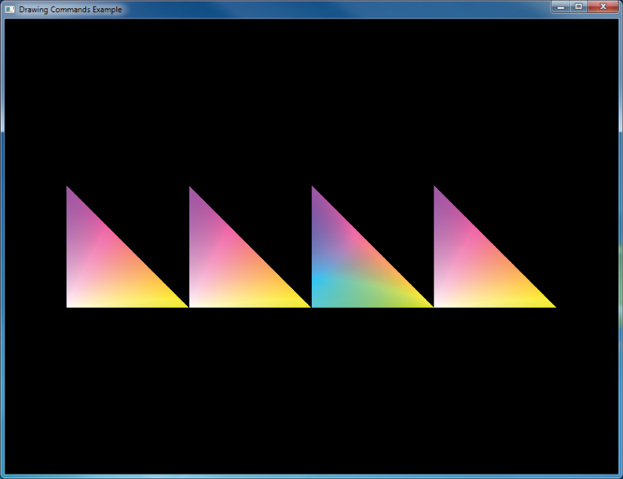
Example 3.6 Drawing Commands Example
// DrawArrays
model_matrix = vmath::translation(-3.0f, 0.0f, -5.0f);
glUniformMatrix4fv(render_model_matrix_loc, 4, GL_FALSE, model_matrix);
glDrawArrays(GL_TRIANGLES, 0, 3);
// DrawElements
model_matrix = vmath::translation(-1.0f, 0.0f, -5.0f);
glUniformMatrix4fv(render_model_matrix_loc, 4, GL_FALSE, model_matrix);
glDrawElements(GL_TRIANGLES, 3, GL_UNSIGNED_SHORT, NULL);
// DrawElementsBaseVertex
model_matrix = vmath::translation(1.0f, 0.0f, -5.0f);
glUniformMatrix4fv(render_model_matrix_loc, 4, GL_FALSE, model_matrix);
glDrawElementsBaseVertex(GL_TRIANGLES, 3, GL_UNSIGNED_SHORT, NULL, 1);
// DrawArraysInstanced
model_matrix = vmath::translation(3.0f, 0.0f, -5.0f);
glUniformMatrix4fv(render_model_matrix_loc, 4, GL_FALSE, model_matrix);
glDrawArraysInstanced(GL_TRIANGLES, 0, 3, 1);
The result of the program in Examples 3.5 and 3.6 is shown in Figure 3.5. It’s not terribly exciting, but you can see four similar triangles, each rendered using a different drawing command.
Restarting Primitives
As you start working with larger sets of vertex data, you are likely to find that you need to make numerous calls to the OpenGL drawing routines, usually rendering the same type of primitive (such as GL_TRIANGLE_STRIP) that you used in the previous drawing call. Of course, you can use the glMultiDraw*() routines, but they require the overhead of maintaining the arrays for the starting index and length of each primitive.
OpenGL has the ability to restart primitives within the same drawing command by specifying a special value, the primitive restart index, which is specially processed by OpenGL. When the primitive restart index is encountered in a draw call, a new rendering primitive of the same type is started with the vertex following the index. The primitive restart index is specified by the glPrimitiveRestartIndex() function.
As vertices are rendered with one of the glDrawElements() derived function calls, OpenGL can watch for the index specified by glPrimitiveRestartIndex() to appear in the element array buffer. However, it watches only for this index to appear if primitive restating is enabled. Primitive restarting is controlled by calling glEnable() or glDisable() with the GL_PRIMITIVE_RESTART parameter.
To illustrate, consider the layout of vertices in Figure 3.6, which shows how a triangle strip would be broken in two by using primitive restarting. In this figure, the primitive restart index has been set to 8. As the triangles are rendered, OpenGL watches for the index 8 to be read from the element array buffer, and when it sees it go by, rather than creating a vertex, it ends the current triangle strip. The next vertex (vertex 9) becomes the first vertex of a new triangle strip, and so in this case two triangle strips are created.

The following example demonstrates a simple use of primitive restart—it draws a cube as a pair of triangle strips separated by a primitive restart index. Examples 3.7 and 3.8 demonstrate how the data for the cube is specified and then drawn.
Example 3.7 Intializing Data for a Cube Made of Two Triangle Strips
// 8 corners of a cube, side length 2, centered on the origin
static const GLfloat cube_positions[] =
{
-1.0f, -1.0f, -1.0f, 1.0f,
-1.0f, -1.0f, 1.0f, 1.0f,
-1.0f, 1.0f, -1.0f, 1.0f,
-1.0f, 1.0f, 1.0f, 1.0f,
1.0f, -1.0f, -1.0f, 1.0f,
1.0f, -1.0f, 1.0f, 1.0f,
1.0f, 1.0f, -1.0f, 1.0f,
1.0f, 1.0f, 1.0f, 1.0f
};
// Color for each vertex
static const GLfloat cube_colors[] =
{
1.0f, 1.0f, 1.0f, 1.0f,
1.0f, 1.0f, 0.0f, 1.0f,
1.0f, 0.0f, 1.0f, 1.0f,
1.0f, 0.0f, 0.0f, 1.0f,
0.0f, 1.0f, 1.0f, 1.0f,
0.0f, 1.0f, 0.0f, 1.0f,
0.0f, 0.0f, 1.0f, 1.0f,
0.5f, 0.5f, 0.5f, 1.0f
};
// Indices for the triangle strips
static const GLushort cube_indices[] =
{
0, 1, 2, 3, 6, 7, 4, 5, // First strip
0xFFFF, // <<-- This is the restart index
2, 6, 0, 4, 1, 5, 3, 7 // Second strip
};
// Set up the element array buffer
glGenBuffers(1, ebo);
glBindBuffer(GL_ELEMENT_ARRAY_BUFFER, ebo[0]);
glBufferData(GL_ELEMENT_ARRAY_BUFFER,
sizeof(cube_indices),
cube_indices, GL_STATIC_DRAW);
// Set up the vertex attributes
glGenVertexArrays(1, vao);
glBindVertexArray(vao[0]);
glGenBuffers(1, vbo);
glBindBuffer(GL_ARRAY_BUFFER, vbo[0]);
glBufferData(GL_ARRAY_BUFFER,
sizeof(cube_positions) + sizeof(cube_colors),
NULL, GL_STATIC_DRAW);
glBufferSubData(GL_ARRAY_BUFFER, 0,
sizeof(cube_positions), cube_positions);
glBufferSubData(GL_ARRAY_BUFFER, sizeof(cube_positions),
sizeof(cube_colors), cube_colors);
glVertexAttribPointer(0, 4, GL_FLOAT,
GL_FALSE, 0, NULL);
glVertexAttribPointer(1, 4, GL_FLOAT,
GL_FALSE, 0,
(const GLvoid *)sizeof(cube_positions));
glEnableVertexAttribArray(0);
glEnableVertexAttribArray(1);
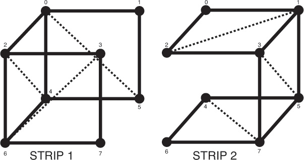
Figure 3.7 shows how the vertex data given in Example 3.7 represents the cube as two independent triangle strips.
Example 3.8 Drawing a Cube Made of Two Triangle Strips Using Primitive Restart
// Set up for a glDrawElements call
glBindVertexArray(vao[0]);
glBindBuffer(GL_ELEMENT_ARRAY_BUFFER, ebo[0]);
#if USE_PRIMITIVE_RESTART
// When primitive restart is on, we can call one draw command
glEnable(GL_PRIMITIVE_RESTART);
glPrimitiveRestartIndex(0xFFFF);
glDrawElements(GL_TRIANGLE_STRIP, 17, GL_UNSIGNED_SHORT, NULL);
#else
// Without primitive restart, we need to call two draw commands
glDrawElements(GL_TRIANGLE_STRIP, 8, GL_UNSIGNED_SHORT, NULL);
glDrawElements(GL_TRIANGLE_STRIP, 8, GL_UNSIGNED_SHORT,
(const GLvoid *)(9 * sizeof(GLushort)));
#endif
Note
OpenGL will restart primitives whenever it comes across the current restart index in the element array buffer. Therefore, it’s a good idea to set the restart index to a value that will not be used in your code. The default restart index is zero, which is very likely to appear in your element array buffer. A good value to choose is 2n – 1, where n is the number of bits in your indices (i.e., 16 for GL_UNSIGNED_SHORT indices and 32 for GL_UNSIGNED_INT indices). This is very unlikely to be used as a real index. Sticking with such a standard also means that you don’t need to figure out the index for every model in your program.
Instanced Rendering
Instancing, or instanced rendering, is a way of executing the same drawing commands many times in a row, with each producing a slightly different result. This can be a very efficient method of rendering a large amount of geometry with very few API calls. Several variants of already-familiar drawing functions exist to instruct OpenGL to execute the command multiple times. Further, various mechanisms are available in OpenGL to allow the shader to use the instance of the draw as an input, and to be given new values for vertex attributes per-instance rather than per-vertex. The simplest instanced rendering call is
This is the instanced version of glDrawArrays(); note the similarity of the two functions. The parameters of glDrawArraysInstanced() are identical to those of glDrawArrays(), with the addition of the primCount argument. This parameter specifies the count of the number of instances that are to be rendered. When this function is executed, OpenGL will essentially execute primCount copies of glDrawArrays(), with the mode, first, and count parameters passed through. There are *Instanced versions of several of the OpenGL drawing commands, including glDrawElementsInstanced() (for glDrawElements()) and glDrawElementsInstancedBaseVertex() (for glDrawElementsBaseVertex()). The glDrawElementsInstanced() function is defined as
Again, note that the parameters to glDrawElementsInstanced() are identical to glDrawElements(), with the addition of primCount. Each time one of the instanced functions is called, OpenGL essentially runs the whole command as many times as is specified by the primCount parameter. This on its own is not terribly useful. However, there are two mechanisms provided by OpenGL that allow vertex attributes to be specified as instanced and to provide the vertex shader with the index of the current instance.
Instanced Vertex Attributes
Instanced vertex attributes behave similarly to regular vertex attributes. They are declared and used in exactly the same way inside the vertex shader. On the application side, they are also configured in the same way as regular vertex attributes. That is, they are backed by buffer objects, can be queried with glGetAttribLocation(), set up using glVertexAttribPointer(), and enabled and disabled using glEnableVertexAttribArray() and glDisableVertexAttribArray(). The important new function that allows a vertex attribute to become instanced is as follows:
The glVertexAttribDivisor() function controls the rate at which the vertex attribute is updated. index is the index of the vertex attribute whose divisor is to be set and is the same as would be passed to glVertexAttribPointer() or glEnableVertexAttribArray(). By default, a new value of each enabled attribute is delivered to each vertex. Setting divisor to zero resets the attribute to this behavior and makes it a regular, noninstanced attribute. A nonzero value of divisor makes the attribute instanced and causes a new value to be fetched from the attribute array once every divisor instances rather than for every vertex. The index within the enabled vertex attribute array from which the attribute is taken is then ![]() , where instance is the current instance number and divisor is the value of divisor for the current attribute. For each of the instanced vertex attributes, the same value is delivered to the vertex shader for all vertices in the instance. If divisor is two, the value of the attribute is updated every second instance; if it is three, the attribute is updated every third instance, and so on. Consider the vertex attributes declared in Example 3.9, some of which will be configured as instanced.
, where instance is the current instance number and divisor is the value of divisor for the current attribute. For each of the instanced vertex attributes, the same value is delivered to the vertex shader for all vertices in the instance. If divisor is two, the value of the attribute is updated every second instance; if it is three, the attribute is updated every third instance, and so on. Consider the vertex attributes declared in Example 3.9, some of which will be configured as instanced.
Example 3.9 Vertex Shader Attributes for the Instancing Example
#version 410 core
// 'position' and 'normal' are regular vertex attributes
layout (location = 0) in vec4 position;
layout (location = 1) in vec3 normal;
// Color is a per-instance attribute
layout (location = 2) in vec4 color;
// model_matrix will be used as a per-instance transformation
// matrix. Note that a mat4 consumes 4 consecutive locations, so
// this will actually sit in locations, 3, 4, 5, and 6.
layout (location = 3) in mat4 model_matrix;
Note that in Example 3.9, there is nothing special about the declaration of the instanced vertex attributes color and model_matrix. Now consider the code shown in Example 3.10, which configures a subset of vertex attributes declared in Example 3.9 as instanced.
Example 3.10 Example Setup for Instanced Vertex Attributes
// Get the locations of the vertex attributes in 'prog', which is
// the (linked) program object that we're going to be rendering
// with. Note that this isn't really necessary because we specified
// locations for all the attributes in our vertex shader. This code
// could be made more concise by assuming the vertex attributes are
// where we asked the compiler to put them.
int position_loc = glGetAttribLocation(prog, "position");
int normal_loc = glGetAttribLocation(prog, "normal");
int color_loc = glGetAttribLocation(prog, "color");
int matrix_loc = glGetAttribLocation(prog, "model_matrix");
// Configure the regular vertex attribute arrays -
// position and normal.
glBindBuffer(GL_ARRAY_BUFFER, position_buffer);
glVertexAttribPointer(position_loc, 4, GL_FLOAT, GL_FALSE, 0, NULL);
glEnableVertexAttribArray(position_loc);
glBindBuffer(GL_ARRAY_BUFFER, normal_buffer);
glVertexAttribPointer(normal_loc, 3, GL_FLOAT, GL_FALSE, 0, NULL);
glEnableVertexAttribArray(normal_loc);
// Now we set up the color array. We want each instance of our
// geometry to assume a different color, so we just pack colors
// into a buffer object and make an instanced vertex attribute out
// of it.
glBindBuffer(GL_ARRAY_BUFFER, color_buffer);
glVertexAttribPointer(color_loc, 4, GL_FLOAT, GL_FALSE, 0, NULL);
glEnableVertexAttribArray(color_loc);
// This is the important bit... set the divisor for the color array
// to 1 to get OpenGL to give us a new value of 'color' per-instance
// rather than per-vertex.
glVertexAttribDivisor(color_loc, 1);
// Likewise, we can do the same with the model matrix. Note that a
// matrix input to the vertex shader consumes N consecutive input
// locations, where N is the number of columns in the matrix. So...
// we have four vertex attributes to set up.
glBindBuffer(GL_ARRAY_BUFFER, model_matrix_buffer);
// Loop over each column of the matrix...
for (int i = 0; i < 4; i++)
{
// Set up the vertex attribute
glVertexAttribPointer(matrix_loc + i, // Location
4, GL_FLOAT, GL_FALSE, // vec4
sizeof(mat4), // Stride
(void *)(sizeof(vec4) * i)); // Start offset
// Enable it
glEnableVertexAttribArray(matrix_loc + i);
// Make it instanced
glVertexAttribDivisor(matrix_loc + i, 1);
}
In Example 3.10, position and normal are regular, noninstanced vertex attributes. However, color is configured as an instanced vertex attribute with a divisor of one. This means that each instance will have a new value for the color attribute (which will be constant across all vertices in the instance). Further, the model_matrix attribute will also be made instanced to provide a new model transformation matrix for each instance. A mat4 attribute is consuming a consecutive location. Therefore, we loop over each column in the matrix and configure it separately. The remainder of the vertex shader is shown in Example 3.11.
Example 3.11 Instanced Attributes Example Vertex Shader
// The view matrix and the projection matrix are constant
// across a draw
uniform mat4 view_matrix;
uniform mat4 projection_matrix;
// The output of the vertex shader (matched to the
// fragment shader)
out VERTEX
{
vec3 normal;
vec4 color;
} vertex;
// Ok, go!
void main(void)
{
// Construct a model-view matrix from the uniform view matrix
// and the per-instance model matrix.
mat4 model_view_matrix = view_matrix * model_matrix;
// Transform position by the model-view matrix, then by the
// projection matrix.
gl_Position = projection_matrix * (model_view_matrix *
position);
// Transform the normal by the upper-left-3x3-submatrix of the
// model-view matrix
vertex.normal = mat3(model_view_matrix) * normal;
// Pass the per-instance color through to the fragment shader.
vertex.color = color;
}
The code to set the model matrices for the instances and then draw the instanced geometry using these shaders is shown in Example 3.12. Each instance has its own model matrix, whereas the view matrix (consisting of a rotation around the y axis followed by a translation in z) is common to all instances. The model matrices are written directly into the buffer by mapping it using glMapBuffer(). Each model matrix translates the object away from the origin and then rotates the translated model around the origin. The view and projection matrices are simply placed in uniform variables. Then a single call to glDrawArraysInstanced() is used to draw all instances of the model.
Example 3.12 Instancing Example Drawing Code
// Map the buffer
mat4 * matrices = (mat4 *)glMapBuffer(GL_ARRAY_BUFFER,
GL_WRITE_ONLY);
// Set model matrices for each instance
for (n = 0; n < INSTANCE_COUNT; n++)
{
float a = 50.0f * float(n) / 4.0f;
float b = 50.0f * float(n) / 5.0f;
float c = 50.0f * float(n) / 6.0f;
matrices[n] = rotation(a + t * 360.0f, 1.0f, 0.0f, 0.0f) *
rotation(b + t * 360.0f, 0.0f, 1.0f, 0.0f) *
rotation(c + t * 360.0f, 0.0f, 0.0f, 1.0f) *
translation(10.0f + a, 40.0f + b, 50.0f + c);
}
// Done. Unmap the buffer.
glUnmapBuffer(GL_ARRAY_BUFFER);
// Activate instancing program
glUseProgram(render_prog);
// Set up the view and projection matrices
mat4 view_matrix(translation(0.0f, 0.0f, -1500.0f) *
rotation(t * 360.0f * 2.0f, 0.0f, 1.0f, 0.0f));
mat4 projection_matrix(frustum(-1.0f, 1.0f,
-aspect, aspect, 1.0f, 5000.0f));
glUniformMatrix4fv(view_matrix_loc, 1,
GL_FALSE, view_matrix);
glUniformMatrix4fv(projection_matrix_loc, 1,
GL_FALSE, projection_matrix);
// Render INSTANCE_COUNT objects
glDrawArraysInstanced(GL_TRIANGLES, 0, object_size, INSTANCE_COUNT);
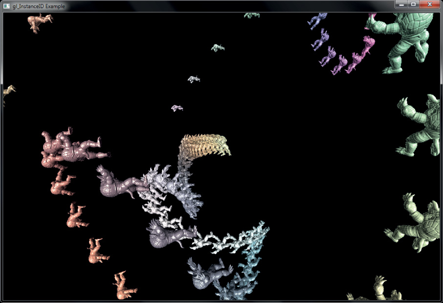
The result of the program is shown in Figure 3.8. In this example, the constant INSTANCE_COUNT (which is referenced in the code of Examples 3.10 and 3.12) is 100. One hundred copies of the model are drawn, each with a different position and a different color. These models could very easily be trees in a forest, spaceships in a fleet, or buildings in a city.

There are some inefficiencies in the example shown in Examples 3.9 through 3.12. Work that will produce the same result across all of the vertices in an instance will still be performed per-vertex. Sometimes there are ways to get around this. For example, the computation of model_view_matrix will evaluate to the same matrix for all vertices within a single instance. Here, we could avoid this work by using a second instanced mat4 attribute to carry the per-instance model-view matrix. In other cases, it may not be possible to avoid this work, but it may be possible to move it into a geometry shader so that work is performed once per-primitive rather than once per-vertex, or perhaps use geometry shader instancing instead. Both of these techniques will be explained in Chapter 10.
Note
Remember that calling an instanced drawing command is mostly equivalent to calling its noninstanced counterpart many times before executing any other OpenGL commands. Therefore, converting a sequence of OpenGL functions called inside a loop to a sequence of instanced draw calls will not produce identical results.
Another example of a way to use instanced vertex attributes is to pack a set of textures into a 2D array texture and then pass the array slice to be used for each instance in an instanced vertex attribute. The vertex shader can pass the instance’s slice into the fragment shader, which can then render each instance of the geometry with a different texture.
It is possible to internally add an offset to the indices used to fetch instanced vertex attributes from vertex buffers. Similar to the baseVertex parameter that is available through glDrawElementsBaseVertex(), the instance offset is exposed through an additional baseInstance parameter in some versions of the instanced drawing functions. The functions that take a baseInstance parameter are glDrawArraysInstancedBaseInstance(), glDrawElementsInstancedBaseInstance(), and glDrawElementsInstancedBaseVertexBaseInstance(). Their prototypes are as follows:
Using the Instance Counter in Shaders
In addition to instanced vertex attributes, the index of the current instance is available to the vertex shader in the built-in variable gl_InstanceID. This variable is implicitly declared as an integer. It starts counting from zero and counts up one each time an instance is rendered. gl_InstanceID is always present in the vertex shader, even when the current drawing command is not one of the instanced ones. In those cases, it will just be zero. The value in gl_InstanceID may be used to index into uniform arrays, perform texture lookups as the input to an analytic function, or for any other purpose.
In the following example, the functionality of Examples 3.9 through 3.12 is replicated by using gl_InstanceID to index into texture buffer objects (TBOs) rather than through the use of instanced vertex attributes. Here, the vertex attributes of Example 3.9 are replaced with TBO lookups and so are removed from the vertex attribute setup code. Instead, a first TBO containing color of each instance and a second TBO containing the model matrices are created. The vertex attribute declaration and setup code are the same as in Examples 3.9 and 3.10 (with the omission of the color and model_matrix attributes, of course). As the instance’s color and model matrix is now explicitly fetched in the vertex shader, more code is added to the body of the vertex shader, which is shown in Example 3.13.
Example 3.13 gl_VertexID Example Vertex Shader
// The view matrix and the projection matrix are constant across a draw
uniform mat4 view_matrix;
uniform mat4 projection_matrix;
// These are the TBOs that hold per-instance colors and per-instance
// model matrices
uniform samplerBuffer color_tbo;
uniform samplerBuffer model_matrix_tbo;
// The output of the vertex shader (matched to the fragment shader)
out VERTEX
{
vec3 normal;
vec4 color;
} vertex;
// Ok, go!
void main(void)
{
// Use gl_InstanceID to obtain the instance color from the color TBO
vec4 color = texelFetch(color_tbo, gl_InstanceID);
// Generating the model matrix is more complex because you can't
// store mat4 data in a TBO. Instead, we need to store each
// matrix as four vec4 variables and assemble the matrix in the
// shader. First, fetch the four columns of the matrix
// (remember, matrices are stored in memory in column-major
// order).
vec4 col1 = texelFetch(model_matrix_tbo, gl_InstanceID * 4);
vec4 col2 = texelFetch(model_matrix_tbo, gl_InstanceID * 4 + 1);
vec4 col3 = texelFetch(model_matrix_tbo, gl_InstanceID * 4 + 2);
vec4 col4 = texelFetch(model_matrix_tbo, gl_InstanceID * 4 + 3);
// Now assemble the four columns into a matrix.
mat4 model_matrix = mat4(col1, col2, col3, col4);
// Construct a model-view matrix from the uniform view matrix
// and the per-instance model matrix.
mat4 model_view_matrix = view_matrix * model_matrix;
// Transform position by the model-view matrix, then by the
// projection matrix.
gl_Position = projection_matrix * (model_view_matrix *
position);
// Transform the normal by the upper-left-3x3-submatrix of the
// model-view matrix
vertex.normal = mat3(model_view_matrix) * normal;
// Pass the per-instance color through to the fragment shader.
vertex.color = color;
}
To drive the shader of Example 3.13, we need to create and initialize TBOs to back the color_tbo and model_matrix_tbo samplers rather than initializing the instanced vertex attributes. However, aside from the differences in setup code, the program is essentially unchanged. Example 3.14 contains the code to set up the TBOs for use with the shader of Example 3.13.
Example 3.14 Example Setup for Instanced Vertex Attributes
// Get the locations of the vertex attributes in 'prog', which is
// the (linked) program object that we're going to be rendering
// with. Note that this isn't really necessary because we specified
// locations for all the attributes in our vertex shader. This code
// could be made more concise by assuming the vertex attributes are
// where we asked the compiler to put them.
int position_loc = glGetAttribLocation(prog, "position");
int normal_loc = glGetAttribLocation(prog, "normal");
// Configure the regular vertex attribute arrays - position and normal.
glBindBuffer(GL_ARRAY_BUFFER, position_buffer);
glVertexAttribPointer(position_loc, 4, GL_FLOAT, GL_FALSE, 0, NULL);
glEnableVertexAttribArray(position_loc);
glBindBuffer(GL_ARRAY_BUFFER, normal_buffer);
glVertexAttribPointer(normal_loc, 3, GL_FLOAT, GL_FALSE, 0, NULL);
glEnableVertexAttribArray(normal_loc);
// Now set up the TBOs for the instance colors and model matrices...
// First, create the TBO to store colors, bind a buffer to it and
// initialize its format. The buffer has previously been created
// and sized to store one vec4 per-instance.
glCreateTextures(1, GL_TEXTURE_BUFFER, &color_tbo);
glTextureBuffer(color_tbo, GL_RGBA32F, color_buffer);
glBindTextureUnit(0, color_buffer);
// Now do the same thing with a TBO for the model matrices. The
// buffer object (model_matrix_buffer) has been created and sized
// to store one mat4 per-instance.
glCreateTextures(1, GL_TEXTURE_BUFFER, &model_matrix_tbo);
glTextureBuffer(model_matrix_tbo, GL_RGBA32F, model_matrix_buffer);
glBindTextureUnit(1, model_matrix_tbo);
Note that the code in Example 3.14 is actually shorter and simpler than that in Example 3.10. This is because we have shifted the responsibility for fetching per-instance data from built-in OpenGL functionality to the shader writer. This can be seen in the increased complexity of Example 3.13 relative to Example 3.11. With this responsibility comes additional power and flexibility. For example, if the number of instances is small, it may be preferable to use a uniform array rather than a TBO for data storage, which may increase performance. Regardless, there are very few other changes that need to be made to the original example to move to using explicit fetches driven by gl_InstanceID. In fact, the rendering code of Example 3.12 is used intact to produce an identical result to the original program. The proof is in the screen shot (Figure 3.9).
• Create some vertex shader inputs that you intend to be instanced.
• Set the vertex attribute divisors with glVertexAttribDivisor().
• Use the gl_InstanceID built-in variable in the vertex shader.
• Use the instanced versions of the rendering functions such as glDrawArraysInstanced(), glDrawElementsInstanced(), or glDrawElementsInstancedBaseVertex().