
Appendix C. Built-in GLSL Variables and Functions
The OpenGL Shading Language has a small number of built-in variables, a set of constants, and a large collection of built-in functions. This appendix describes each of these, in the following major sections:
• “Built-in Variables” lists the variables, first showing the declarations for all stages, followed by a description of each stage.
• “Built-in Constants” lists all the built-in constants.
• “Built-in Functions” describes all GLSL built-in functions. You’ll need to refer to the table at the beginning of the section to decode the types.
Built-in Variables
Each programmable stage has a different set of built-in variables, though there is some overlap. We show all the built-in variable declarations in the “Built-in Variable Declarations” section and then describe each one in the “Built-in Variable Descriptions” section.
Built-in Variable Declarations
Vertex Shader Built-in Variables
in int gl_VertexID;
in int gl_InstanceID;
out gl_PerVertex {
vec4 gl_Position;
float gl_PointSize;
float gl_ClipDistance[];
float gl_CullDistance[];
};
Tessellation Control Shader Built-in Variables
in gl_PerVertex {
vec4 gl_Position;
float gl_PointSize;
float gl_ClipDistance[];
float gl_CullDistance[];
} gl_in[gl_MaxPatchVertices];
in int gl_PatchVerticesIn;
in int gl_PrimitiveID;
in int gl_InvocationID;
out gl_PerVertex {
vec4 gl_Position;
float gl_PointSize;
float gl_ClipDistance[];
float gl_CullDistance[];
} gl_out[];
patch out float gl_TessLevelOuter[4];
patch out float gl_TessLevelInner[2];
Tessellation Evaluation Shader Built-in Variables
in gl_PerVertex {
vec4 gl_Position;
float gl_PointSize;
float gl_ClipDistance[];
float gl_CullDistance[];
} gl_in[gl_MaxPatchVertices];
in int gl_PatchVerticesIn;
in int gl_PrimitiveID;
in vec3 gl_TessCoord;
patch in float gl_TessLevelOuter[4];
patch in float gl_TessLevelInner[2];
out gl_PerVertex {
vec4 gl_Position;
float gl_PointSize;
float gl_ClipDistance[];
float gl_CullDistance[];
};
Geometry Shader Built-in Variables
in gl_PerVertex {
vec4 gl_Position;
float gl_PointSize;
float gl_ClipDistance[];
float gl_CullDistance[];
} gl_in[];
in int gl_PrimitiveIDIn;
in int gl_InvocationID;
out gl_PerVertex {
vec4 gl_Position;
float gl_PointSize;
float gl_ClipDistance[];
float gl_CullDistance[];
};
out int gl_PrimitiveID;
out int gl_Layer;
out int gl_ViewportIndex;
Fragment Shader Built-in Variables
in vec4 gl_FragCoord;
in bool gl_FrontFacing;
in float gl_ClipDistance[];
in float gl_CullDistance[];
in vec2 gl_PointCoord;
in int gl_PrimitiveID;
in int gl_SampleID;
in vec2 gl_SamplePosition;
in int gl_SampleMaskIn[];
in int gl_Layer;
in int gl_ViewportIndex;
in bool gl_HelperInvocation;
out float gl_FragDepth;
out int gl_SampleMask[];
Compute Shader Built-in Variables
// workgroup dimensions
in uvec3 gl_NumWorkGroups;
const uvec3 gl_WorkGroupSize;
// work group and invocation IDs
in uvec3 gl_WorkGroupID;
in uvec3 gl_LocalInvocationID;
// derived variables
in uvec3 gl_GlobalInvocationID;
in uint gl_LocalInvocationIndex;
All Shader Stages’ Built-in State Variables
struct gl_DepthRangeParameters {
float near;
float far;
float diff;
};
uniform gl_DepthRangeParameters gl_DepthRange;
uniform int gl_NumSamples;
Built-in Variable Descriptions
The descriptions of each of these declared variables are given here in alphabetical order.
gl_ClipDistance[]
This provides the mechanism for controlling user clipping. The element gl_ClipDistance[i] specifies a clip distance for each plane [i]. A distance of 0 means the vertex is on the plane, a positive distance means the vertex is inside the clip plane, and a negative distance means the point is outside the clip plane. The output clip distances will be linearly interpolated across the primitive, and the portion of the primitive with interpolated distances less than 0 will be clipped.
The gl_ClipDistance[] array is predeclared as unsized and must be sized by the shader, either redeclaring it with a size or indexing it only with integral constant expressions. This needs to size the array to include all the clip planes that are enabled via the OpenGL API; if the size does not include all enabled planes, results are undefined. The size can be at most gl_MaxClipDistances. The number of varying components (gl_MaxVaryingComponents) consumed by gl_ClipDistance[] will match the size of the array, no matter how many planes are enabled. The shader must also set all values in gl_ClipDistance[] that have been enabled via the OpenGL API, or results are undefined. Values written into gl_ClipDistance[] for planes that are not enabled have no effect.
As an output variable, gl_ClipDistance[] provides the place for the shader to write these distances. As an input in all shaders except fragment shaders, it reads the values written in the previous shader stage. In a fragment shader, gl_ClipDistance[] array contains linearly interpolated values for the vertex values written by a shader to the gl_ClipDistance[] vertex output variable. Only elements in this array that have clipping enabled will have defined values.
gl_CullDistance[]
This provides a mechanism for controlling user culling of primitives. The element gl_CullDistance[i] specifies a cull distance for plane i. A distance of 0 means the vertex is on the plane, a positive distance means the vertex is inside the cull volume, and a negative distance means the point is outside the cull volume. Primitives whose vertices all have a negative clip distance for plane i will be discarded.
The gl_CullDistance array is predeclared as unsized and must be sized by the shader, either redeclaring it with a size or indexing it only with integral constant expressions. The size determines the number and set of enabled cull distances and can be at most gl_MaxCullDistances. The number of varying components (see gl_MaxVaryingComponents) consumed by gl_CullDistance will match the size of the array. Shaders writing gl_CullDistance must write all enabled distances, or culling results are undefined. As an output variable, gl_CullDistance provides the place for the shader to write these distances. As an input in all but the fragment language, it reads the values written in the previous shader stage. In the fragment language, gl_CullDistance array contains linearly interpolated values for the vertex values written by a shader to the gl_CullDistance vertex output variable. It is a compile-time or link-time error for the set of shaders forming a program to have the sum of the sizes of the gl_ClipDistance and gl_CullDistance arrays to be larger than gl_MaxCombinedClipAndCullDistances.
gl_DepthRange
The structure gl_DepthRange contains the locations of the near clip plane and far clip plane for viewport 0. Values are given in window coordinates. The field diff contains the difference far - near.
gl_FragCoord
The fixed functionality computed depth for a fragment may be obtained by reading gl_FragCoord.z.
The gl_FragCoord fragment shader input variable holds the window relative coordinates (x, y, z, ![]() ) values for the current fragment.
) values for the current fragment.
If multisampling, this value can be for any location within the pixel. It is the result of the fixed functionality that interpolates primitives after vertex processing to generate fragments. The z component is the depth value that would be used for the fragment’s depth if no shader contained any writes to gl_FragDepth. This is useful for invariance if a shader conditionally computes gl_FragDepth but otherwise wants the fixed functionality fragment depth.
gl_FragDepth
Writing to gl_FragDepth in a fragment shader will establish the depth value for the fragment being processed. If depth buffering is enabled, and no shader writes gl_FragDepth, the fixed function value for depth will be used as the fragment’s depth value. If a shader in the fragment stage contains any assignment anywhere to gl_FragDepth, and there is an execution path through the shader that does not set gl_FragDepth, the value of the fragment’s depth might not be undefined when the nonassigning path is taken. So if you write it anywhere, make sure all paths write it.
gl_FrontFacing
Fragment shaders can read the input built-in variable gl_FrontFacing, whose value is true if the fragment belongs to a front-facing primitive. One use of this is to emulate two-sided lighting by selecting one of two colors calculated by a vertex or geometry shader.
gl_GlobalInvocationID
The compute shader input gl_GlobalInvocationID contains the global index of the current work item. This value uniquely identifies this invocation from all other invocations across all local and global workgroups initiated by the current glDispatchCompute call. This is computed as follows:
gl_GlobalInvocationID =
gl_WorkGroupID * gl_WorkGroupSize + gl_LocalInvocationID;
gl_InstanceID
The vertex shader input gl_InstanceID holds the instance number of the current primitive in an instanced draw call. If the current primitive does not come from an instanced draw call, the value of gl_InstanceID is zero.
gl_InvocationID
Tessellation control and geometry shaders can read gl_InvocationID. In the tessellation control shader, it identifies the number of the output patch vertex assigned to the tessellation control shader invocation. In the geometry shader, it identifies the invocation number assigned to the geometry shader invocation. In both cases, gl_InvocationID is assigned integer values in the range [0, N – 1], where N is the number of output patch vertices or geometry shader invocations per primitive.
gl_Layer
The gl_Layer variable is both an output from geometry shaders and an input to fragment shaders. In a geometry shader, it is used to select a specific layer (or face and layer of a cube map) of a multilayer framebuffer attachment. The actual layer used will come from one of the vertices in the primitive being shaded. Which vertex the layer comes from is undefined, so it is best to write the same layer value for all vertices of a primitive. If any geometry shader in a program contains an assignment to gl_Layer, layered rendering mode is enabled. Once enabled, if there is an execution path through the shader that does not set gl_Layer, it will be undefined. So ensure that you always set it for all paths through the shader.
The output variable gl_Layer takes on a special value when used with an array of cube-map textures. Instead of referring only to the layer, it is used to select a cube-map face and a layer. Setting gl_Layer to the value layer × 6 + face will render to face face of the cube defined in layer layer. The face values are shown in Table C.1.
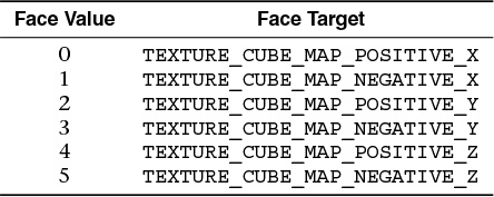
For example, to render to the positive y cube-map face located in the fifth layer of the cube-map array, gl_Layer should be set to 5 × 6 + 2.
The gl_Layer input to a fragment shader will have the same value that was written to the gl_Layer output from the geometry shader. If no shader in the geometry stage dynamically assigns a value to gl_Layer, the value of gl_Layer in the fragment shaders will be undefined. If the geometry stage contains no assignment at all to gl_Layer, the input gl_Value in the fragment stage will be zero. Otherwise, the fragment stage will read the same value written by the geometry stage, even if that value is out of range. If a fragment shader contains any access to gl_Layer, it will count against the implementation-defined limit for the maximum number of inputs to the fragment stage.
gl_LocalInvocationID
The compute shader input gl_LocalInvocationID contains the t-dimensional index of the local workgroup within the global workgroup that the current invocation is executing in. The possible values for this variable range across the local workgroup size are
(0,0,0)
to
(gl_WorkGroupSize.x - 1, gl_WorkGroupSize.y - 1, gl_WorkGroupSize.z - 1)
gl_LocalInvocationIndex
The compute shader input gl_LocalInvocationIndex contains the one-dimensional representation of the gl_LocalInvocationID. This is useful for uniquely identifying a unique region of shared memory within the local workgroup for this invocation to use. It is computed as follows:
gl_LocalInvocationIndex =
gl_LocalInvocationID.z * gl_WorkGroupSize.x * gl_WorkGroupSize.y +
gl_LocalInvocationID.y * gl_WorkGroupSize.x +
gl_LocalInvocationID.x;
gl_NumSamples
The uniform input gl_NumSamples to all stages contains the total number of samples in the framebuffer when a multisample framebuffer is used. When a nonmultisample framebuffer is used, gl_NumSamples contains 1.
gl_NumWorkGroups
The compute shader input gl_NumWorkGroups contains the total number of global work items in each dimension of the workgroup that will execute the compute shader. Its content is equal to the values specified in the num_groups_x, num_groups_y, and num_groups_z parameters passed to the glDispatchCompute API entry point.
gl_PatchVerticesIn
Tessellation shaders can read gl_PatchVerticesIn. It is an integer specifying the number of vertices in the input patch being processed by the shader. A single tessellation control or evaluation shader can read patches of differing sizes, so the value of gl_PatchVerticesIn may differ between patches.
gl_PointCoord
The values in gl_PointCoord are two-dimensional coordinates indicating where within a point primitive the current fragment is located when point sprites are enabled. They range from 0.0 to 1.0 across the point. If the current primitive is not a point, or if point sprites are not enabled, the values read from gl_PointCoord are undefined.
gl_PointSize
As an output variable, gl_PointSize is intended for a shader to write the size of the point to be rasterized. It is measured in pixels. If gl_PointSize is not written to, its value is undefined in subsequent stages. As an input variable, gl_PointSize reads the value written to gl_PointSize in the previous shader stage.
gl_Position
As an output variable, gl_Position is intended for writing the homogeneous vertex position. This value will be used by primitive assembly, clipping, culling, and other fixed functionality operations, if present, that operate on primitives after vertex processing has occurred. Its value is undefined after the vertex processing stage if the vertex shader executable does not write gl_Position, and it is undefined after geometry processing if the geometry executable calls EmitVertex without having written gl_Position since the last EmitVertex (or hasn’t written it at all). As an input variable, gl_Position reads the output written in the previous shader stage to gl_Position.
gl_PrimitiveID
Geometry shaders output gl_PrimitiveID to provide a single integer that serves as a primitive identifier. This is then available to fragment shaders as the fragment input gl_PrimitiveID, which will select the written primitive ID from the provoking vertex in the primitive being shaded. If a fragment shader using gl_PrimitiveID is active and a geometry shader is also active, the geometry shader must write to gl_PrimitiveID, or the fragment shader input gl_PrimitiveID is undefined.
For tessellation control and evaluation shaders, the input variable gl_PrimitiveID is filled with the number of primitives processed by the shader since the current set of rendering primitives was started. For the fragment shader, it is filled with the value written to the gl_PrimitiveID geometry shader output if a geometry shader is present. Otherwise, it is assigned in the same manner as with tessellation control and evaluation shaders.
gl_PrimitiveIDIn
The geometry shader input variable gl_PrimitiveIDIn behaves identically to the tessellation control and evaluation shader input variable gl_PrimitiveID.
gl_SampleID
The fragment shader input variable gl_SampleID is filled with the sample number of the sample currently being processed. This variable is in the range 0 to gl_NumSamples-1, where gl_NumSamples is the total number of samples in the framebuffer, or 1 if rendering to a nonmultisample framebuffer. Any use of this variable in a fragment shader causes the entire shader to be evaluated per sample.
gl_SampleMask
The fragment output array gl_SampleMask[] sets the sample mask for the fragment being processed. Coverage for the current fragment will become the logical AND of the coverage mask and the output gl_SampleMask. This array must be sized in the fragment shader either implicitly or explicitly to be the same size described next, under “gl_SampleMaskin.”
If any fragment shader contains any assignment to gl_SampleMask, the sample mask will be undefined for any array elements of any fragment shader invocations that fail to assign a value. If no shader has any assignment to gl_SampleMask, the sample mask has no effect on the processing of a fragment.
Bit B of mask gl_SampleMask[ M] corresponds to sample 32 × M + B. There are ceil($s$/32) array elements, where s is the maximum number of color samples supported by the implementation.
gl_SampleMaskIn
The fragment shader input gl_SampleMaskIn indicates the set of samples covered by the primitive generating the fragment during multisample rasterization. It has a sample bit set if, and only if, the sample is considered covered for this fragment shader invocation.
Bit B of mask gl_SampleMaskIn[ M] corresponds to sample 32 × M + B. There are ceil($s$/32) array elements, where s is the maximum number of color samples supported by the implementation.
gl_SamplePosition
The fragment shader input gl_SamplePosition contains the position of the current sample within the multisample draw buffer. The x and y components of gl_SamplePosition contain the subpixel coordinate of the current sample and will have values in the range 0.0 to 1.0. Any use of this variable in any fragment shader causes the entire fragment stage to be evaluated per sample.
gl_TessCoord
The variable gl_TessCoord is available only in tessellation evaluation shaders. It specifies a three-component (u, v, w) vector identifying the position of the vertex being processed by the shader relative to the primitive being tessellated. Its values will obey the properties
gl_TessCoord.x == 1.0 - (1.0 - gl_TessCoord.x)
gl_TessCoord.y == 1.0 - (1.0 - gl_TessCoord.y)
gl_TessCoord.z == 1.0 - (1.0 - gl_TessCoord.z)
to aid in replicating subdivision computations.
gl_TessLevelOuter and gl_TessLevelOuter
The input variables gl_TessLevelOuter[] and gl_TessLevelInner[] are available only in tessellation evaluation shaders. If a tessellation control shader is active, these variables are filled with corresponding outputs written by the tessellation control shader. Otherwise, they are assigned with default tessellation levels.
The output variables gl_TessLevelOuter[] and gl_TessLevelInner[] are available only in tessellation control shaders. The values written to these variables are assigned to the corresponding outer and inner tessellation levels of the output patch. They are used by the tessellation primitive generator to control primitive tessellation and may be read by tessellation evaluation shaders.
gl_ViewportID
The vertex shader input gl_VertexID holds an integer index for the vertex. While the variable gl_VertexID is always present, its value is not always defined.
gl_ViewportIndex
The variable gl_ViewportIndex is available as an output variable from geometry shaders and an input variable to fragment shaders. In geometry shaders, it provides the index of the viewport to which the next primitive emitted from the geometry shader should be drawn. Primitives generated by the geometry shader will undergo viewport transformation and scissor testing using the viewport transformation and scissor rectangle selected by the value of gl_ViewportIndex. The viewport index used will come from one of the vertices in the primitive being shaded. However, which vertex the viewport index comes from is implementation-dependent, so it is best to use the same viewport index for all vertices of the primitive. If a geometry shader does not assign a value to gl_ViewportIndex, viewport transform and scissor rectangle zero will be used. If any geometry shader assigns a value to gl_ViewportIndex, and there is a path through the geometry stage that does not assign a value to gl_ViewportIndex, the value of gl_ViewportIndex is undefined for executions of the shader that take that path.
As a fragment shader input, gl_ViewportIndex will have the same value that was written to the output variable gl_ViewportIndex in the geometry stage. If the geometry stage does not dynamically assign to gl_ViewportIndex, the value of gl_ViewportIndex in the fragment shader will be undefined. If the geometry stage contains no assignment to gl_ViewportIndex, the fragment stage will read zero. Otherwise, the fragment stage will read the same value written by the geometry stage, even if that value is out of range. If a fragment shader contains any access to gl_ViewportIndex, it will count against the implementation-defined limit for the maximum number of inputs to the fragment stage.
gl_WorkGroupID
The compute shader input gl_WorkGroupID contains the three-dimensional index of the global workgroup that the current invocation is executing in. The possible values range across the parameters passed into glDispatchCompute, from
(0, 0, 0)
to
(gl_NumWorkGroups.x - 1, gl_NumWorkGroups.y - 1, gl_NumWorkGroups.z - 1)
gl_WorkGroupSize
The built-in constant gl_WorkGroupSize is a compute shader constant containing the local workgroup size of the shader. The size of the workgroup in the x, y, and z dimensions is stored in the x, y, and z components. The values stored in gl_WorkGroupSize match those specified in the required local_size_x, local_size_y, and local_size_z layout qualifiers for the current shader. This value is a constant so that it can be used to size arrays of memory that can be shared within the local workgroup.
Built-in Constants
The constants are relatively self-explanatory and referred to as needed by other sections. The following numbers are not necessarily the numbers you will see on your rendering platform. Rather, the numbers you will see on any particular platform will be at least as big as these:
const ivec3 gl_MaxComputeWorkGroupCount = { 65535, 65535, 65535 };
const ivec3 gl_MaxComputeWorkGroupSize = { 1024, 1024, 64 };
const int gl_MaxComputeUniformComponents = 1024;
const int gl_MaxComputeTextureImageUnits = 16;
const int gl_MaxComputeImageUniforms = 8;
const int gl_MaxComputeAtomicCounters = 8;
const int gl_MaxComputeAtomicCounterBuffers = 8;
const int gl_MaxVertexAttribs = 16;
const int gl_MaxVertexUniformComponents = 1024;
const int gl_MaxVaryingComponents = 60;
const int gl_MaxVertexOutputComponents = 64;
const int gl_MaxGeometryInputComponents = 64;
const int gl_MaxGeometryOutputComponents = 128;
const int gl_MaxFragmentInputComponents = 128;
const int gl_MaxVertexTextureImageUnits = 16;
const int gl_MaxCombinedTextureImageUnits = 96;
const int gl_MaxTextureImageUnits = 16;
const int gl_MaxImageUnits = 8;
const int gl_MaxCombinedShaderOutputResources = 8;
const int gl_MaxImageSamples = 0;
const int gl_MaxVertexImageUniforms = 0;
const int gl_MaxTessControlImageUniforms = 0;
const int gl_MaxTessEvaluationImageUniforms = 0;
const int gl_MaxGeometryImageUniforms = 0;
const int gl_MaxFragmentImageUniforms = 8;
const int gl_MaxCombinedImageUniforms = 8;
const int gl_MaxFragmentUniformComponents = 1024;
const int gl_MaxDrawBuffers = 8;
const int gl_MaxClipDistances = 8;
const int gl_MaxGeometryTextureImageUnits = 16;
const int gl_MaxGeometryOutputVertices = 256;
const int gl_MaxGeometryTotalOutputComponents = 1024;
const int gl_MaxGeometryUniformComponents = 1024;
const int gl_MaxTessControlInputComponents = 128;
const int gl_MaxTessControlOutputComponents = 128;
const int gl_MaxTessControlTextureImageUnits = 16;
const int gl_MaxTessControlUniformComponents = 1024;
const int gl_MaxTessControlTotalOutputComponents = 4096;
const int gl_MaxTessEvaluationInputComponents = 128;
const int gl_MaxTessEvaluationOutputComponents = 128;
const int gl_MaxTessEvaluationTextureImageUnits = 16;
const int gl_MaxTessEvaluationUniformComponents = 1024;
const int gl_MaxTessPatchComponents = 120;
const int gl_MaxPatchVertices = 32;
const int gl_MaxTessGenLevel = 64;
const int gl_MaxViewports = 16;
const int gl_MaxVertexUniformVectors = 256;
const int gl_MaxFragmentUniformVectors = 256;
const int gl_MaxVaryingVectors = 15;
const int gl_MaxVertexAtomicCounters = 0;
const int gl_MaxTessControlAtomicCounters = 0;
const int gl_MaxTessEvaluationAtomicCounters = 0;
const int gl_MaxGeometryAtomicCounters = 0;
const int gl_MaxFragmentAtomicCounters = 8;
const int gl_MaxCombinedAtomicCounters = 8;
const int gl_MaxAtomicCounterBindings = 1;
const int gl_MaxVertexAtomicCounterBuffers = 0;
const int gl_MaxTessControlAtomicCounterBuffers = 0;
const int gl_MaxTessEvaluationAtomicCounterBuffers = 0;
const int gl_MaxGeometryAtomicCounterBuffers = 0;
const int gl_MaxFragmentAtomicCounterBuffers = 1;
const int gl_MaxCombinedAtomicCounterBuffers = 1;
const int gl_MaxAtomicCounterBufferSize = 32;
const int gl_MinProgramTexelOffset = -8;
const int gl_MaxProgramTexelOffset = 7;
const int gl_MaxTransformFeedbackBuffers = 4;
const int gl_MaxTransformFeedbackInterleavedComponents = 64;
const int gl_MaxCullDistances = 8;
const int gl_MaxCombinedClipAndCullDistances = 8;
const int gl_MaxSamples = 4;
const int gl_MaxVertexImageUniforms = 0;
const int gl_MaxFragmentImageUniforms = 8;
const int gl_MaxComputeImageUniforms = 8;
const int gl_MaxCombinedImageUniforms = 48;
const int gl_MaxCombinedShaderOutputResources = 16;
Built-in Functions
The OpenGL Shading Language defines an assortment of built-in convenience functions for scalar and vector operations. These are grouped here and use the subsequently defined notation for types:
• “Angle and Trigonometry Functions”
• “Common Functions”
• “Floating-Point Pack and Unpack Functions”
• “Matrix Functions”
• “Vector Relational Functions”
• “Image Functions”
• “Fragment Processing Functions”
• “Shader Invocation Control Functions”
• “Shader Memory Control Functions”
Listing all the prototypes for all the GLSL built-in functions would fill this entire book. Instead, we use some generic notations that represent multiple types. These are listed in Table C.2 and allow a single prototype listing to represent multiple actual prototypes.
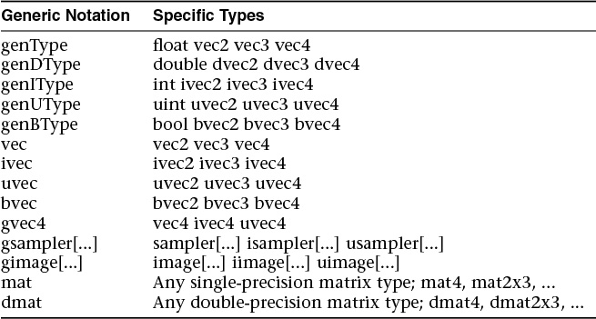
For any specific use of a function, the actual types substituted for genType, genIType, and so on have to have the same number of components for all arguments as well as the return type. When gsampler... is used, the underlying type (floating-point, signed integer, and unsigned integer) must match the underlying type in the gvec4.
One final note: Most built-in functions operate componentwise and are described as though operating on a single component. That is, if the actual type is, say, a vec3, the x component will be operated on as described, independently of the y and z components. Similarly, each of y and z will be operated on independently of the other two components. Unless otherwise noted, the functions operate componentwise. Dot product is a great counterexample, where each component of the result is affected by all the components of the input.
Angle and Trigonometry Functions
Function parameters specified as angle are assumed to be in units of radians.
genType radians(genType degrees);
genType asin(genType x);
Arc sine. Returns an angle whose sine is x. The range of values returned by this function is ![]() to
to ![]() , inclusive.
, inclusive.
genType atan(genType y, genType x);
Arc tangent. Returns an angle whose tangent is ![]() . The signs of x and y are used to determine what quadrant the angle is in. The range of values returned by this function is –π to π, inclusive.
. The signs of x and y are used to determine what quadrant the angle is in. The range of values returned by this function is –π to π, inclusive.
genType atan(genType y over x);
Arc tangent. Returns an angle whose tangent is y over x. The range of values returned by this function is ![]() to
to ![]() , inclusive.
, inclusive.
genType sinh(genType x);
Returns the hyperbolic sine function ![]() .
.
genType cosh(genType x);
Returns the hyperbolic cosine function ![]() .
.
genType tanh(genType x);
Returns the hyperbolic tangent function ![]() .
.
Exponential Functions
genType sqrt(genType x);
genDType sqrt(genDType x);
Return ![]() .
.
genType inversesqrt(genType x);
genDType inversesqrt(genDType x);
Return ![]()
Common Functions
Floating-Point Pack and Unpack Functions
These functions do not operate componentwise but as described in each case.
Geometric Functions
These operate on vectors as vectors, not componentwise.
float length(genType x);
double length(genDType x);
vec3 cross(vec3 x, vec3 y);
dvec3 cross(dvec3 x, dvec3 y);

Matrix Functions
For each of the following built-in matrix functions, there is both a single-precision floating-point version, where all arguments and return values are single-precision, and a double-precision floating-point version, where all arguments and return values are double-precision. Only the single-precision floating-point version is shown.
Vector Relational Functions
The following are for comparing vectors. (Scalars are compared with operators.)
In all cases, the sizes of all the input and return vectors for any particular call must match.
Integer Functions
For these functions, the notation [a, b] means the set of bits from bit number a through bit-number b, inclusive. The lowest-order bit is bit 0. “Bit number” will always refer to counting up from the lowest-order bit as bit 0.
Texture Functions
Texture lookup functions are available in all shading stages. However, level of detail is implicitly computed only for fragment shaders so that OpenGL can automatically perform mipmap filtering. Other shading stages use a base level of detail of zero or use the texture directly if it is not mipmapped. When texture functions require implicit derivatives, they must be called outside of nonuniform control flow. That is, if they are called within control flow that varies from fragment to fragment, there is not enough information to properly compute the level of detail, giving undefined implicit derivatives and, hence, undefined results from the texture lookup.
Texture data can be stored by the GL as single-precision floating-point, unsigned normalized integer, unsigned integer, or signed integer data. This is determined by the type of the internal format of the texture. Texture lookups on unsigned normalized integer and floating-point data return floating-point values in the range [0.0, 1.0].
Texture lookup functions that can return their result as floating-point, unsigned integer, or signed integer are provided, depending on the sampler type passed to the lookup function. Care must be taken to use the right sampler type for texture access. If an integer sampler type is used, the result of a texture lookup is an ivec4. If an unsigned integer sampler type is used, the result of a texture lookup is a uvec4. If a floating-point sampler type is used, the result of a texture lookup is a vec4, where each component is in the range [0, 1].
For shadow forms (the sampler parameter is a shadow-type), a depth comparison lookup on the depth texture bound to sampler is done. See the following prototypes for which component specifies Dref. The texture bound to sampler must be a depth texture, or results are undefined. If a nonshadow texture call is made to a sampler that represents a depth texture with depth comparisons turned on, results are undefined. If a shadow texture call is made to a sampler that represents a depth texture with depth comparisons turned off, results are undefined. If a shadow texture call is made to a sampler that does not represent a depth texture, results are undefined.
In the following functions, the bias argument is optional for fragment-stage shaders. The bias argument is not accepted in any other stages. For a fragment shader, if bias is present, it is added to the implicit level of detail prior to performing the texture access operation. No bias or lod arguments for rectangle textures, multisample textures, or texture buffers are supported because mipmaps are not allowed for these types of textures.
For Cube forms, the direction of P is used to select which face to do a two-dimensional texture lookup in.
For Array forms, the array layer used will be
max(0, min(d – 1, floor(layer + 0.5)))
where d is the depth of the texture array and layer comes from the component indicated in the prototypes.
For depth-stencil textures, the sampler type should match the component being accessed as set through the OpenGL API. When the depth-stencil texture mode is set to DEPTH_COMPONENT, a floating-point sampler type should be used. When the depth-stencil texture mode is set to STENCIL_INDEX, an unsigned integer sampler type should be used. Doing a texture lookup with an unsupported combination will return undefined values.
Texture Query Functions
The textureSize functions query the dimensions of a specific texture level for a sampler.
The textureQueryLod functions are available only in a fragment shader. They take the components of P and compute the level of detail information that the texture pipe would use to access that texture through a normal texture lookup. The level of detail is obtained after any LOD bias but prior to clamping to [TEXTURE_MIN_LOD, TEXTURE_MAX_LOD]. The mipmap array(s) that would be accessed are also computed. If a single level of detail would be accessed, the level-of-detail number relative to the base level is returned. If multiple levels of detail would be accessed, a floating-point number between the two levels is returned, with the fractional part equal to the fractional part of the computed and clamped level of detail.
Texel Lookup Functions
gvec4 textureLod(gsampler1D sampler, float P, float lod);
gvec4 textureLod(gsampler2D sampler, vec2 P, float lod);
gvec4 textureLod(gsampler3D sampler, vec3 P, float lod);
gvec4 textureLod(gsamplerCube sampler, vec3 P, float lod);
float textureLod(sampler1DShadow sampler, vec3 P, float lod);
float textureLod(sampler2DShadow sampler, vec3 P, float lod);
gvec4 textureLod(gsampler1DArray sampler, vec2 P, float lod);
gvec4 textureLod(gsampler2DArray sampler, vec3 P, float lod);
float textureLod(sampler1DArrayShadow sampler, vec3 P,
float lod);
gvec4 textureLod(gsamplerCubeArray sampler, vec4 P, float lod);
gvec4 textureGrad(gsampler1D sampler, float P, float dPdx,
float dPdy);
gvec4 textureGrad(gsampler2D sampler, vec2 P, vec2 dPdx,
vec2 dPdy);
gvec4 textureGrad(gsampler3D sampler, vec3 P, vec3 dPdx,
vec3 dPdy);
gvec4 textureGrad(gsamplerCube sampler, vec3 P, vec3 dPdx,
vec3 dPdy);
gvec4 textureGrad(gsampler2DRect sampler, vec2 P, vec2 dPdx,
vec2 dPdy);
float textureGrad(sampler2DRectShadow sampler, vec3 P,
vec2 dPdx, vec2 dPdy);
float textureGrad(sampler1DShadow sampler, vec3 P, float dPdx,
float dPdy);
float textureGrad(sampler2DShadow sampler, vec3 P, vec2 dPdx,
vec2 dPdy);
float textureGrad(samplerCubeShadow sampler, vec4 P,
vec3 dPdx, vec3 dPdy);
gvec4 textureGrad(gsampler1DArray sampler, vec2 P, float dPdx,
float dPdy);
gvec4 textureGrad(gsampler2DArray sampler, vec3 P, vec2 dPdx,
vec2 dPdy);
float textureGrad(sampler1DArrayShadow sampler, vec3 P,
float dPdx, float dPdy);
float textureGrad(sampler2DArrayShadow sampler, vec4 P,
vec2 dPdx, vec2 dPdy);
gvec4 textureGrad(gsamplerCubeArray sampler, vec4 P,
vec3 dPdx, vec3 dPdy);
Texture Gather Functions
The texture gather functions take components of a single floating-point vector operand as a texture coordinate, determine a set of four texels to sample from the base level of detail of the specified texture image, and return one component from each texel in a four-component result vector.
When performing a texture gather operation, the minification and magnification filters are ignored, and the rules for LINEAR filtering are applied to the base level of the texture image to identify the four texels i0j1, i1j1, i1j0, and i0j0. The texels are then converted to texture base colors (Rs, Gs, Bs, As), followed by application of the texture swizzle. A four-component vector is assembled by taking the selected component from each of the post-swizzled texture source colors in the order (i0j1, i1j1, i1j0, i0j0).
For texture gather functions using a shadow sampler type, each of the four texel lookups performs a depth comparison against the depth reference value passed in refZ and returns the result of that comparison in the appropriate component of the result vector.
As with other texture lookup functions, the results of a texture gather are undefined for shadow samplers if the texture referenced is not a depth texture or has depth comparisons disabled, or for nonshadow samplers if the texture referenced is a depth texture with depth comparisons enabled.
Atomic-Counter Functions
The atomic-counter operations in this section operate atomically with respect to each other. They are atomic for any single counter, meaning that any of these operations on a specific counter in one shader instantiation will be indivisible by any of these operations on the same counter from another shader instantiation. There is no guarantee that these operations are atomic with respect to other forms of access to the counter or that they are serialized when applied to separate counters. Such cases would require additional use of fences, barriers, or other forms of synchronization if atomicity or serialization is desired. The value returned by an atomic-counter function is the value of an atomic counter, which may be returned and incremented in an atomic operation, decremented and returned in an atomic operation, or simply returned. The underlying counter is a 32-bit unsigned integer. Increments and decrements at the limit of the range will wrap to [0, 232 – 1].
Atomic Memory Functions
Atomic memory functions perform atomic operations on an individual signed or unsigned integer stored in buffer-object or shared-variable storage. All of the atomic memory operations read a value from memory, compute a new value using one of the operations, write the new value to memory, and return the original value read. The contents of the memory being updated by the atomic operation are guaranteed not to be modified by any other assignment or atomic memory function in any shader invocation between the time the original value is read and the time the new value is written. Atomic memory functions are supported for only a limited set of variables. A shader will fail to compile if the value passed to the mem argument of an atomic memory function does not correspond to a buffer or shared variable. It is acceptable to pass an element of an array or a single component of a vector to the mem argument of an atomic memory function as long as the underlying array or vector is a buffer or shared variable.
Image Functions
Variables using one of the image basic types may be used by the built-in shader image memory functions defined in this section to read and write individual texels of a texture. Each image variable references an image unit, which has a texture image attached.
When the image functions access memory, an individual texel in the image is identified using an (i), (i, j), or (i, j, k) coordinate corresponding to the values of P. For image2DMS and image2DMSArray variables (and the corresponding signed- and unsigned-int types) corresponding to multisample textures, each texel may have multiple samples, and an individual sample is identified using the integer sample argument.
Loads and stores support float, integer, and unsigned integer types. The IMAGE_PARAMS in the following prototypes is a placeholder representing 33 separate functions, each for a different type of image variable. The IMAGE_PARAMS placeholder is replaced by one of the parameter lists
• gimage1D image, int P
• gimage2D image, ivec2 P
• gimage3D image, ivec3 P
• gimage2DRect image, ivec2 P
• gimageCube image, ivec3 P
• gimageBuffer image, int P
• gimage1DArray image, ivec2 P
• gimage2DArray image, ivec3 P
• gimageCubeArray image, ivec3 P
• gimage2DMS image, ivec2 P, int sample
• gimage2DMSArray image, ivec3 P, int sample
where each of the lines represents one of three different image variable types and image, P, and sample specify the individual texel to operate on.
The atomic functions perform atomic operations on individual texels or samples of an image variable. Atomic memory operations read a value from the selected texel, compute a new value using one of the operations, write the new value to the selected texel, and return the original value read. The contents of the texel being updated by the atomic operation are guaranteed not to be modified by any other image store or atomic function between the time the original value is read and the time the new value is written.
Atomic memory operations are supported on only a subset of all image variable types; image must be either
• A signed integer image variable (type starts “iimage”) and a format qualifier of r32i, used with a data argument of type int, or
• An unsigned image variable (type starts “uimage”) and a format qualifier of r32ui, used with a data argument of type uint.
Fragment Processing Functions
Fragment processing functions are available only in fragment shaders.
Derivative Functions
OpenGL implementations typically approximate derivatives by comparing a computed expression’s value at neighboring fragments. Hence, when this is requested within nonuniform control flow (lines of the shader that are conditionally executed, where the condition varies from pixel to pixel), the derivative is undefined.
Interpolation Functions
Built-in interpolation functions are available to compute an interpolated value of a fragment shader input variable at a shader-specified (x, y) location. A separate (x, y) location may be used for each invocation of the built-in function, and those locations may differ from the default (x, y) location used to produce the default value of the input. For all of the interpolation functions, interpolant must be an input variable or an element of an input variable declared as an array. Component selection operators (e.g., .xy) may not be used when specifying interpolant. If interpolant is declared with a flat or centroid qualifier, the qualifier will have no effect on the interpolated value. If interpolant is declared with the noperspective qualifier, the interpolated value will be computed without perspective correction.
Geometry Shader Functions
These functions are available only in geometry shaders to manage the output data streams created by this stage.
The function EmitStreamVertex specifies that a vertex is completed. A vertex is added to the current output primitive in vertex stream stream using the current values of all output variables associated with stream. These include gl_PointSize, gl_ClipDistance[], gl_CullDistance[], gl_Layer, gl_Position, gl_PrimitiveID, and gl_ViewportIndex. The values of all output variables for all output streams are undefined after a call to EmitStreamVertex. If a geometry shader invocation has emitted more vertices than permitted by the output layout qualifier max_vertices, the results of calling EmitStreamVertex are undefined.
The function EndStreamPrimitive specifies that the current output primitive for vertex stream stream is completed and a new output primitive (of the same type) will be started by any subsequent EmitStreamVertex. This function does not emit a vertex. If the output layout is declared to be “points,” calling EndStreamPrimitive is optional.
A geometry shader starts with an output primitive containing no vertices for each stream. When a geometry shader terminates, the current output primitive for each stream is automatically completed. It is not necessary to call EndStreamPrimitive if the geometry shader writes only a single primitive.
Multiple output streams are supported only if the output primitive type is declared to be points. A program will fail to link if it contains a geometry shader calling EmitStreamVertex or EndStreamPrimitive if its output primitive type is not points.
Shader Invocation Control Functions
The shader invocation control function is available only in tessellation control shaders and compute shaders. It is used to control the relative execution order of multiple shader invocations used to process a patch (in the case of tessellation control shaders) or a local workgroup (in the case of compute shaders), which are otherwise executed with an undefined relative order.
The function barrier provides a partially defined order of execution between shader invocations. This ensures that values written by one invocation prior to a given static instance of barrier can be safely read by other invocations after their call to the same static instance barrier. Because invocations may execute in undefined order between these barrier calls, the values of a per-vertex or per-patch output variable or shared variables for compute shaders will be undefined in some cases. The barrier function may be placed only inside the function main of the tessellation control shader and may not be called within any control flow. Barriers are also disallowed after a return statement in the function main. Any such misplaced barriers result in a compile-time error.
Shader Memory Control Functions
Shaders of all types may read and write the contents of textures and buffer objects using image variables. While the order of reads and writes within a single shader invocation is well defined, the relative order of reads and writes to a single shared memory address from multiple separate shader invocations is largely undefined. The order of memory accesses performed by one shader invocation, as observed by other shader invocations, is also largely undefined but can be controlled through memory control functions.
The memory barrier built-in functions can be used to order reads and writes to variables stored in memory accessible to other shader invocations. When called, these functions will wait for the completion of all reads and writes previously performed by the caller that accessed selected variable types and then return with no other effect. The built-in functions memoryBarrierAtomicCounter, memoryBarrierBuffer, memoryBarrierImage, and memoryBarrierShared wait for the completion of accesses to atomic counter, buffer, image, and shared variables, respectively. The built-in functions memoryBarrier and groupMemoryBarrier wait for the completion of accesses to all of the above variable types. The functions memoryBarrierShared and groupMemoryBarrier are available only in compute shaders; the other functions are available in all shader types.
When these functions return, the results of any memory stores performed using coherent variables performed prior to the call will be visible to any future coherent access to the same memory performed by any other shader invocation. In particular, the values written this way in one shader stage are guaranteed to be visible to coherent memory accesses performed by shader invocations in subsequent stages when those invocations were triggered by the execution of the original shader invocation (e.g., fragment shader invocations for a primitive resulting from a particular geometry shader invocation).
Additionally, memory barrier functions order stores performed by the calling invocation, as observed by other shader invocations. Without memory barriers, if one shader invocation performs two stores to coherent variables, a second shader invocation might see the values written by the second store prior to seeing those written by the first. However, if the first shader invocation calls a memory barrier function between the two stores, selected other shader invocations will never see the results of the second store before seeing those of the first. When using the function groupMemoryBarrier, this ordering guarantee applies only to other shader invocations in the same compute shader workgroup; all other memory barrier functions provide the guarantee to all other shader invocations. No memory barrier is required to guarantee the order of memory stores as observed by the invocation performing the stores; an invocation reading from a variable that it previously wrote will always see the most recently written value unless another shader invocation also wrote to the same memory.