
Several applications of modulation techniques for audio effects are presented in the literature [Dut98a, War98, Dis99]. We will now summarize some of these effects.
3.4.1 Vibrato
The cyclic variation of the pitch of the input signal is the basic application of the phase modulator described in the previous section. A detailed description can be found in Section 2.6.1.
3.4.2 Stereo Phaser
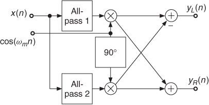
The application of a SSB modulator for a stereo phaser is described in [War98]. Figure 3.11 shows a SSB modulator performed by a recursive allpass implementation of a Hilbert filter. The phase difference of 90° is achieved through specially designed allpass filters.
Figure 3.11 Stereo phaser based on SSB modulation [War98].
3.4.3 Rotary Loudspeaker Effect
Introduction
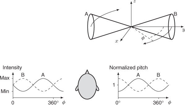
The rotary loudspeaker effect was first used for the electronic reproduction of organ instruments. Figure 3.12 shows the configuration of a rotating bi-directional loudspeaker horn in front of a listener. The sound in the listener's ears is altered by the Doppler effect, the directional characteristic of the speakers and phase effects due to air turbulence. The Doppler effect raises and lowers the pitch according to the rotation speed. The directional characteristic of the opposite horn arrangement performs an intensity variation in the listener's ears. Both the pitch modification and the intensity variation are performed by speaker A and in the opposite direction by speaker B.
Figure 3.12 Rotary loudspeaker [DZ99].
Signal Processing
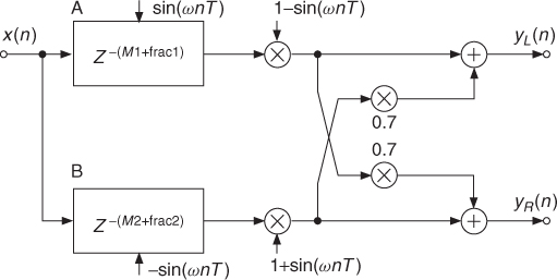
A combination of modulation and delay line modulation can be used for a rotary loudspeaker effect simulation [DZ99], as shown in Figure 3.13. The simulation makes use of a modulated delay line for pitch modifications and amplitude modulation for intensity modifications. The simulation of the Doppler effect of two opposite horns is done by the use of two delay lines modulated with 180° phase shifted signals in vibrato configuration (see Figure 3.13). A directional sound characteristic similar to rotating speakers can be achieved by amplitude modulating the output signal of the delay lines. The modulation is synchronous to the delay modulation in a manner that the back-moving horn has lower pitch and decreasing amplitude. At the return point the pitch is unaltered and the amplitude is minimum. The movement in direction to the listener causes a raised pitch and increasing amplitude. A stereo rotary speaker effect is perceived due to unequal mixing of the two delay lines to the left and right channel output.
Figure 3.13 Rotary loudspeaker simulation [DZ99].
Musical Applications
By imprinting amplitude and pitch modulations as well as some spatialization, this effect makes the sounds more lively. At lower rotation speeds it is reminiscent of the echoes in a cathedral, whereas at higher rotation speeds it gets a ring-modulation flavor. This effect is known as “Leslie” from the name of Donald E. Leslie, who invented it in the early forties. It was licensed to electronic organ manufacturers such as Baldwin, Hammond or Wurlitzer, but it has also found applications for other musical instruments such as the guitar or even the voice (“Blue Jay Way” on the Beatles LP “Magical Mystery Tour” [Sch94].) A demonstration of a Leslie simulator can be heard on [m-Pie99]. This effect can also be interpreted as a rotating microphone between two loudspeakers. You may also imagine that you are sitting on a merry-go-round and you pass by two loudspeakers.
3.4.4 SSB Effects
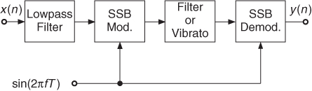
Single-side-band modulation can be used for detuning of percussion instruments or voices. The harmonic frequency relations are modified by using this technique. Another application is time-variant filtering: first use SSB modulation to shift the input spectrum, apply filtering or phase modulation and then perform the demodulation of the signal, as shown in Figure 3.14 [Dis99, DZ99]. The frequency shift of the input signal is achieved by a low-frequency sinusoid. Arbitrary filters can be used in-between modulation and demodulation.
Figure 3.14 SSB modulation-filtering-demodulation: if a vibrato is performed instead of the filter a mechanical vibrato bar simulation is achieved.
The simulation of the mechanical vibrato bar of an electric guitar can be achieved by applying a vibrato instead of a filter [DZ99]. Such a vibrato bar alters the pitch of the lower strings of the guitar in larger amounts than the higher strings and thus a non-harmonic vibrato results. The SSB approach can also be used for the construction of modified flangers. Further applications of SSB modulation techniques for audio effects are presented in [Dut98a, War98].
3.4.5 Simple Morphing: Amplitude Following
In the context of audio effects, “morphing” means to impose a feature of one sound onto another. The amplitude envelope and the spectrum, as well as the time structure are features that can be morphed. Morphing the amplitude envelope can be achieved by the amplitude follower, whereas morphing a spectrum or a time structure can be achieved by the use of convolution (see Section 2.2.7).
Introduction
Envelope following is one of various methods developed to breathe more life into synthetic sounds. The amplitude envelope of a control signal, usually coming from a real acoustical source, is measured and used to control the amplitude of the synthetic sounds. For example, the amplitude envelope of speech can be used to control the amplitude of broadband noise. Through this process the noise seems to have been articulated like voice. A refinement of this method has led to the development of the vocoder, where the same process is applied in each of the frequency bands into which the voice as well as the noise are divided.
Signal Processing
The input signal is multiplied with the output of the envelope generator for the controlling signal. When an accurate measurement is desired, a RMS detector should be used. However, signals from acoustic instruments usually have fairly limited amplitude variations and their loudness variations are more dependent on spectrum modifications than on amplitude modifications. If the loudness of the output signal has to be similar to that of the controlling signal, then an expansion of the dynamic of the controlling signal should be performed. An effective way to expand the dynamic by a factor of 2 is to eliminate the root extraction from the scaler and use a much simpler MS (mean square) detector.
Musical Applications and Control
In “Swim, swan,” Kiyoshi Furukawa has extended the sound of a clarinet by additional synthetic sounds. In order to link these sounds intimately to the clarinet, their amplitude is controlled by that of the clarinet. In this case, the input sound is the synthetic sound and the controlling sound is the clarinet. The mixing of the synthetic sounds with the clarinet is done in the acoustic domain of the performance space [m-Fur93].
The amplitude variations of the controlling signal applied to the input signal produce an effect that is perceived in the time domain or in the frequency domain, according to the frequency content of the modulating signal. For sub-audio rates (below 20 Hz) the effect will appear in the time domain and we will call it “amplitude following,” whereas for audio modulation rates (above 20 Hz), the effect will be perceived in the frequency domain and will be recognized as an amplitude modulation.
If the control signal has a large bandwidth, the spectrum of the amplitude will have to be reduced by the averager. Typical settings for the decay time constant of the averager are in the range of 30 to 100 ms. Such values will smooth out the amplitude signal so that it remains in the sub-audio range. However, it is often desired that the attacks that are present in the control signal, are morphed onto the input signal as attacks and are not smoothed out by the averager. This is why it is recommended to use a shorter attack time constant than the decay time constant. Typical values are in the range of 1 to 30 ms.
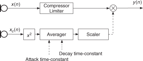
The amplitude variations of the input signal could be opposite to those of the controlling signal, hence reducing the impact of the effect, or be similar and provoke an expansion of the dynamic. In order to get amplitude variations at the output that are similar to those of the controlling signal, it is recommended to process the input signal through a compressor-limiter beforehand [Hal95, p. 40], leading to the system in Figure 3.15.
Figure 3.15 The amplitude of an input signal x(n) is controlled by that of another signal xc(n). The amplitude of the input signal is leveled in a pre-processing step before modulation by the amplitude of the controlling signal is performed.
In his work “Diario polacco,” Luigi Nono specifies how the singer should move away from her microphone in order to produce amplitude modifications that are used to control the amplitude of other sounds [(Hal95, p. 67–68)].
Applying an amplitude envelope can produce interesting modifications of the input signal. Take, for example, the sustained sound of a flute and apply iteratively a triangular amplitude envelope. By varying the slopes of the envelope and the iteration rate, the original sound can be affected by a tremolo or a Flatterzunge and evoke percussive instruments [Dut88]. Such sound transformations are reminiscent of those (anamorphoses) that the early electroacoustic composers were fond of [m-Sch98].
3.4.6 Modulation Vocoder
Novel modulation based effects can be realized within a so-called modulation vocoder (MODVOC). A multi-band modulation decomposition [DE09b] dissects the audio signal into a signal adaptive set of analytic bandpass signals, each of which is further divided into a sinusoidal carrier and its amplitude modulation (AM) and frequency modulation (FM). A set of bandpass filters is computed such that on the one hand the full-band spectrum is covered seamlessly and on the other hand the filters are aligned with local centers of gravity (COGs). The local COG corresponds to the mean frequency that is perceived by a listener due to the spectral contributions in that frequency region and can be modeled by a sinusoidal carrier. Both AM and FM are captured in the amplitude envelope and the phase of the bandpass signals heterodyned by their respective carriers.
A block diagram of the signal decomposition is depicted in Figure 3.16. In the diagram, the schematic signal flow for the extraction of one of the multi-band components is shown. All other components are obtained in a similar fashion. First, a broadband input signal x is fed into a front-end bandpass filter that has been designed signal adaptively, yielding an output signal ![]() . Next, the analytic signal is derived by the Hilbert transform according to Equation 3.20
. Next, the analytic signal is derived by the Hilbert transform according to Equation 3.20
The AM is given by the amplitude envelope of ![]()
3.21 ![]()
while the FM is the instantaneous frequency (IF) obtained by the phase derivative of the analytic signal heterodyned by a stationary sinusoidal carrier with the angular frequency ωc of the local COG. The FM can be interpreted as the IF variation of the carrier frequency fc.
3.22 
Figure 3.16 Modulation analysis.
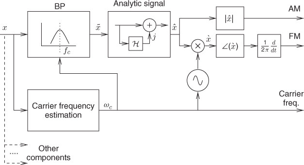
The estimation of local COGs and the signal adaptive design of the front-end filterbank is one of the key parts of the modulation analysis [DE09a]. The MODVOC synthesis renders the output signal on an additive basis from all components. Each component is re-synthesized by modulating its carrier frequency by the associated AM and FM [DE09b].
A global transposition that alters the musical key of an audio signal can be obtained by a simple multiplication of all component carriers with a constant transposition factor. In contrast to other transposition techniques, the transposition of selected MODVOC components also becomes feasible due to the signal adaptive multi-band processing, enabling applications which alter the key mode (e.g., major to minor scale) [DE09b]. However, in the selective transposition there exists an inherent ambiguity with respect to the musical function of each component. Most instruments excite harmonic sounds consisting of a fundamental frequency and its overtones. Since musical intervals obey a logarithmic scale, each harmonic overtone resembles a different musical interval with respect to the fundamental. If the component originates from a fundamental it has to be transposed according to the desired scale mapping; if it is dominated by an overtone to be attributed to a certain fundamental it has to be transposed by the transposition factor of its fundamental in order to best preserve the original timbre. From this, the need emerges for an assignment of each component in order to select the most appropriate transposition factor [DE10].
Another audio effect that can be accomplished within the MODVOC environment, for example, relates to the manipulation of auditory roughness by filtering AM and FM data prior to synthesis [DE08].