
Introduction
Transposition is one of the basic tools of musicians. When we think about providing this effect by signal-processing means, we need to think about the various aspects of it. For a musician, transposing means repeating a melody after pitch shifting it by a fixed interval. Each time the performer transposes the melody, he makes use of a different register of his instrument. By doing so, not only is the pitch of the sound modified, but also the timbre is affected.
In the realm of DAFX, it is a matter of choice to transpose without taking into account the timbre modification or whether the characteristic timbre of the instrument has to be maintained in each of its registers. The first method could be called “variable timbre transposition,” whereas the second approach would be called “constant timbre transposition.” To get an insight into the problem we have to consider the physical origins of the audio signal.
The timbre of a sound heavily depends on the organization of its spectrum. A model can be derived from the study of the singing voice. The pitch of a singing voice is determined by the vocal chords and it can be correlated with the set of frequencies available in the spectrum. The timbre of the voice is mainly determined by the vocal cavities. Their effect is to emphasize some parts of the spectrum, which are called formants. A signal model can be derived where an excitation part is modified by a resonance part. In the case of the voice, the excitation is provided by the vocal chords, hence it is related to the frequencies of the spectrum, whereas the resonances correspond to the formants. When a singer transposes a tune, he has, to some extent, the possibility of modifying the pitch and the formants independently. In a careful signal-processing implementation of this effect, each of these two aspects should be considered.
If only the spectrum of the excitation is stretched or contracted, a pitch transposition up or down, with a constant timbre, is achieved. If only the resonances are stretched or contracted, then the pitch remains the same, but the timbre is varied. Harmonic singing relies on this effect. If both excitation and resonance are deliberately and independently altered, then we enter the domain of effects that can be perceived as unnatural, but that might have a vast musical potential.
The separation of a sound into its excitation and resonance part is a complex process that will be addressed in Chapter 8. We will present here methods which simultaneously alter both aspects, such as the harmonizer or pitch shifting by delay-line modulation in Section 6.4.3. A more refined method based on PSOLA, which allows pitch shifting with formant preservation, will be discussed in Section 6.4.4. For more advanced pitch-shifting methods we refer the reader to 7–11.
Musical Applications
Typical applications of pitch shifting in pop music are the correction of the intonation of instruments or singers, as well as the production of an effect similar to a chorus. When the voice of a singer is mixed with copies of itself that are slightly transposed, a subtle effect appears that gives the impression that one is listening to a choir instead of a single singer.
The harmonizer can also produce surprising effects, such as a man speaking with a tiny high-pitched voice or a female with a gritty low-pitched one. Extreme sounds can be produced such as the deep snare drum sound on David Bowie's “Let's Dance” record [Whi99]. It has also been used for scrambling and unscrambling speech [GRH73]. In combination with a delay line and with feedback of the transposed sound to the input, a kind of spiral can be produced where the sound is always transposed higher or lower at each iteration.
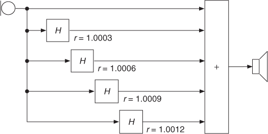
A subtle effect, similar to phasing, can be achieved with a set of harmonizers [Dut88] coupled in parallel and mixed to the input sound, as shown in Figure 6.10. The transposition ratio of the nth harmonizer should be set to 1 + nr where r is of the order of 1/3000. If f0 is the pitch of the sound, the outputs of the nth harmonizer will provide a pitch of f0 + nΔf, where Δf = rf0. If Δf is small enough (a few 1/100 Hz) the interferences between the various outputs of the harmonizers will be clearly audible. When applied, for example, to a low-pitched tuba sound, one harmonic after the other will be emphasized. Flanging and chorus effects can also be achieved by setting the pitch control for a very slight amount of transposition (say, 1/10 to 1/5 of a semitone) and adding regeneration [And95, p. 53]. It appears here that tuning an audio effect is very dependent on the sound being processed. It frequently happens that the tuning has to be adjusted for each new sound or each new pitch.
Figure 6.10 A set of harmonizers that produce a phasing-like effect. It is particularly effective for low-pitched (typically 100 Hz) signals of long duration.
Hans Peter Haller describes in [Hal95, pp. 51–55] some applications of the harmonizer for the production of musical works from Luigi Nono and André Richard.
6.4.1 Historical Methods—Harmonizer
The tape-based machines described in 6.3.2 were also able to modify the pitch of sounds while keeping their initial duration. The Phonogène universel was bulky and could not find a broad diffusion, but in the middle of the 1970s, a digital device appeared that was called a Harmonizer. It implemented in the digital domain a process similar to that of the Phonogène universel. From there on the effect became very popular. Since Harmonizer is a trade mark of the Eventide company, other companies offer similar devices under names such as pitch transposer or pitch shifter.
The main limitation of the use of the harmonizer is the characteristic quality that it gives to the processed sounds. Moles states that the operating range of the Phonogène universel, used as a pitch regulator, was at least −4 to +3 semitones [Mol60, p. 74]. Geslin estimates that the machines available in the late 60s also found application in musique concrète at much larger transposition ratios [Ges00].
The digital implementations in the form of the harmonizer might allow for a better quality, but there are still severe limitations. For transpositions of the order of a semitone, almost no objectionable alteration of the sounds can be heard. As the transposition ratio grows larger, in the practical range of plus or minus two octaves, the timbre of the output sound obtains a character that is specific to the harmonizer.
This modification can be heard both in the frequency domain and in the time domain and is due to the modulation of the signal by the chopping window. The spectrum of the input signal is indeed convolved with that of the window. The time-domain modulation can be characterized by its rate and by the spectrum of the window, which is dependent on its shape and its size. The longer the window, the lower the rate and hence the narrower the spectrum of the window and the less disturbing the modulation. The effect of a trapezoidal window will be stronger than that of a smoother one, such as the raised cosine window.
On the other hand, a larger window tends to deliver, through the overlap-add process, audible iterated copies of the input signals. For the transposition of percussive sounds, it is necessary to reduce the size of the window. Furthermore, to accurately replay transients and not smooth them out, the window should have sharp transitions. We see that a trade-off between audible spectral modulation and iterated transients has to be found for each type of sound. Musicians using the computer as a musical instrument might exploit these peculiarities in the algorithm to give their sound a unique flavor.
6.4.2 Pitch Shifting by Time Stretching and Resampling
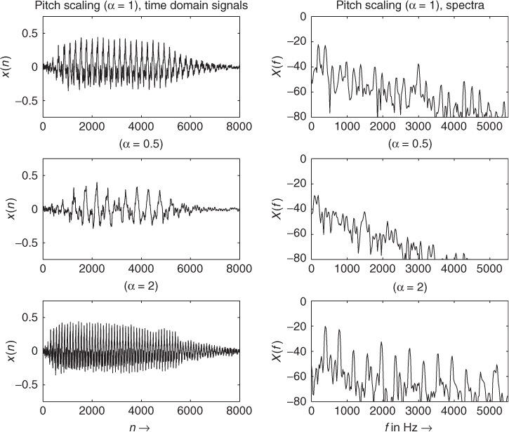
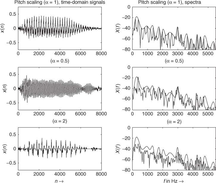
The variable speed replay discussed in Section 6.2 leads to a compression or expansion of the duration of a sound and to a pitch shift. This is accomplished by resampling in the time domain. Figure 6.1 illustrates the discrete-time signals and the corresponding spectra. The spectrum of the sound is compressed or expanded over the frequency axis. The harmonic relations
6.4 ![]()
of the sound are not altered, but are scaled according to
6.5 ![]()
The amplitudes of the harmonics remain the same ![]() . In order to rescale the pitch-shifted sound towards the original length, a further time-stretching algorithm can be applied to the sound. The result of pitch shifting followed by a time-stretching algorithm is illustrated in Figure 6.11.
. In order to rescale the pitch-shifted sound towards the original length, a further time-stretching algorithm can be applied to the sound. The result of pitch shifting followed by a time-stretching algorithm is illustrated in Figure 6.11.
Figure 6.11 Pitch shifting followed by time correction.
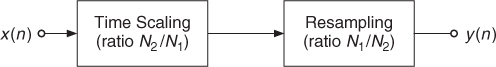
The order of pitch shifting and time scaling can be changed, as shown in Figure 6.12. First, a time-scaling algorithm expands the input signal from length N1 to length N2. Then a resampling operation with the inverse ratio N1/N2 performs pitch shifting and a reduction of length N2 back to length N1. The following M-file 6.4 demonstrates the implementation of the SOLA time-scaling and pitch-scaling algorithm:
M-file 6.4 (PitchScaleSOLA.m)
% PitchScaleSOLA.m
% Authors: G. De Poli, U. Zölzer, P. Dutilleux
% Parameters:
% analysis hop size Sa = 256 (default parmater)
% block length N = 2048 (default parameter)
% pitch scaling factor 0.25 <= alpha <= 2
% overlap interval L = 256*alpha/2
clear all,close all
[signal,Fs] = wavread('x1.wav'),
DAFx_in = signal';
Sa=256;N=2048; % time scaling parameters
M=ceil(length(DAFx_in)/Sa);
n1=512;n2=256; % pitch scaling n1/n2
Ss=round(Sa*n1/n2);
L=256*(n1/n2)/2;
DAFx_in(M*Sa+N)=0;
Overlap=DAFx_in(1:N);
% ****** Time Stretching with alpha=n2/n1******
....... % include main loop TimeScaleSOLA.m
% ****** End Time Stretching ******
% ****** Pitch shifting with alpha=n1/n2 ******
lfen=2048;lfen2=lfen/2;
w1=hanningz(lfen);w2=w1;
% for linear interpolation of a grain of length lx to length lfen
lx=floor(lfen*n1/n2);
x=1+(0:lfen-1)'*lx/lfen;
ix=floor(x);ix1=ix+1;
dx=x-ix;dx1=1-dx;
%
lmax=max(lfen,lx);
Overlap=Overlap';
DAFx_out=zeros(length(DAFx_in),1);
pin=0;pout=0;
pend=length(Overlap)-lmax;
% Pitch shifting by resampling a grain of length lx to length lfen
while pin<pend
grain2=(Overlap(pin+ix).*dx1+Overlap(pin+ix1).*dx).* w1;
DAFx_out(pout+1:pout+lfen)=DAFx_out(pout+1:pout+lfen)+grain2;
pin=pin+n1;pout=pout+n2;
end;
Figure 6.12 Pitch shifting by time scaling and resampling.
6.4.3 Pitch Shifting by Delay-line Modulation
Pitch shifting or pitch transposing based on block processing is described in several publications. In [BB89] a pitch shifter based on an overlap-add scheme with two time-varying delay lines is proposed (see Figure 6.13). A cross-fade block combines the outputs of the two delay lines according to a cross-fade function. The signal is divided in small chunks. The chunks are read faster to produce higher pitches or slower to produce lower pitches. In order to produce a continuous signal output, two chunks are read simultaneously with a time delay equal to one half of the block length. A cross-fade is made from one chunk to the other at each end of a chunk [WG94, pp. 257–259].
Figure 6.13 Pitch shifting.
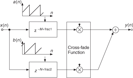
The length of the delay lines is modulated by a sawtooth-type function. A similar approach is proposed in [Dat87], where the same configuration is used for time compression and expansion. A periodicity detection algorithm is used for calculating the cross-fade function in order to avoid cancellations during the cross-fades.
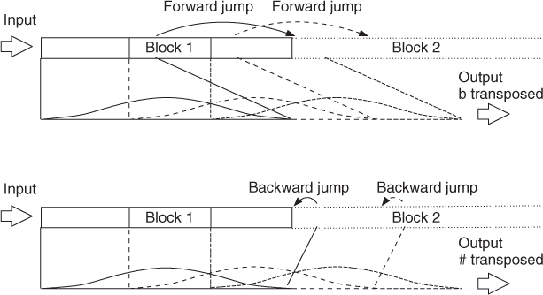
An enhanced method for transposing audio signals is presented in [DZ99]. The method is based on an overlap-add scheme and does not need any fundamental frequency estimation. The difference from other applications is the way the blocks are modulated and combined to the output signal. The enhanced transposing system is based on an overlap-add scheme with three parallel time-varying delay lines (see Figure 6.15).
Figure 6.14 illustrates how the input signal is divided into blocks, which are resampled (phase modulation with a ramp-type signal), amplitude modulated and summed yielding an output signal of the same length as the input signal. Adjacent blocks overlap with 2/3 of the block length.
Figure 6.14 Enhanced pitch transposer: block processing, time shifting and overlap-add.
The modulation signals form a system of three 120°-phase shifted raised cosine functions. The sum of these functions is constant for all arguments. Figure 6.15 also shows the topology of the pitch transposer. Since a complete cosine is used for modulation, the perceived sound quality of the processed signal is much better than in simple twofold overlap-add applications using several windows. The amplitude modulation only produces sum and difference frequencies with the base frequency of the modulation signal, which can be very low (6–10 Hz). Harmonics are not present in the modulation signal and hence cannot form sum or difference frequencies of higher order. The perceived artifacts are phasing-like effects and are less annoying than local discontinuities of other applications based on twofold overlap-add methods.
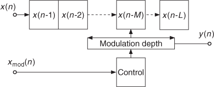
If we want to change the pitch of a signal controlled by another signal or signal envelope, we can also make use of delay-line modulation. The effect can be achieved by performing a phase modulation of the recorded signal according to y(n) = x(n − D(n)). The modulating factor ![]() is now dependent on a modulating signal
is now dependent on a modulating signal ![]() . With this approach the pitch of the input signal x(n) is changed according to the envelope of the modulating signal (see Figure 6.16).
. With this approach the pitch of the input signal x(n) is changed according to the envelope of the modulating signal (see Figure 6.16).
Figure 6.15 Enhanced pitch transposer: block diagram.
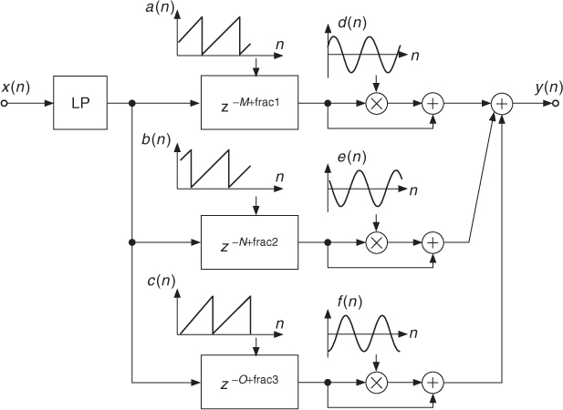
Figure 6.16 Pitch controlled by envelope of signal ![]() .
.
6.4.4 Pitch Shifting by PSOLA and Formant Preservation
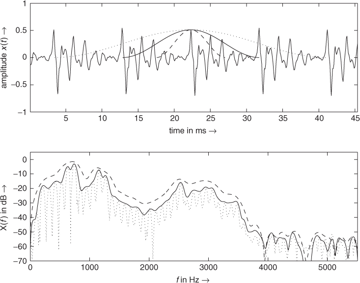
This technique is the dual operation to resampling in the time domain, but in this case a resampling of the short-time spectral envelope is performed. The short-term spectral envelope describes a frequency curve going through all amplitudes of the harmonics. This is demonstrated in Figure 6.17, where the spectral envelope is shown. The harmonics are again scaled according to ![]() , but the amplitudes of the harmonics
, but the amplitudes of the harmonics ![]() are now determined by sampling the spectral envelope. Some deviations of the amplitudes from the precise envelope can be noticed. This depends on the chosen pitch-shifting algorithm.
are now determined by sampling the spectral envelope. Some deviations of the amplitudes from the precise envelope can be noticed. This depends on the chosen pitch-shifting algorithm.
Figure 6.17 Pitch shifting by the PSOLA method: frequency resampling the spectral envelope.
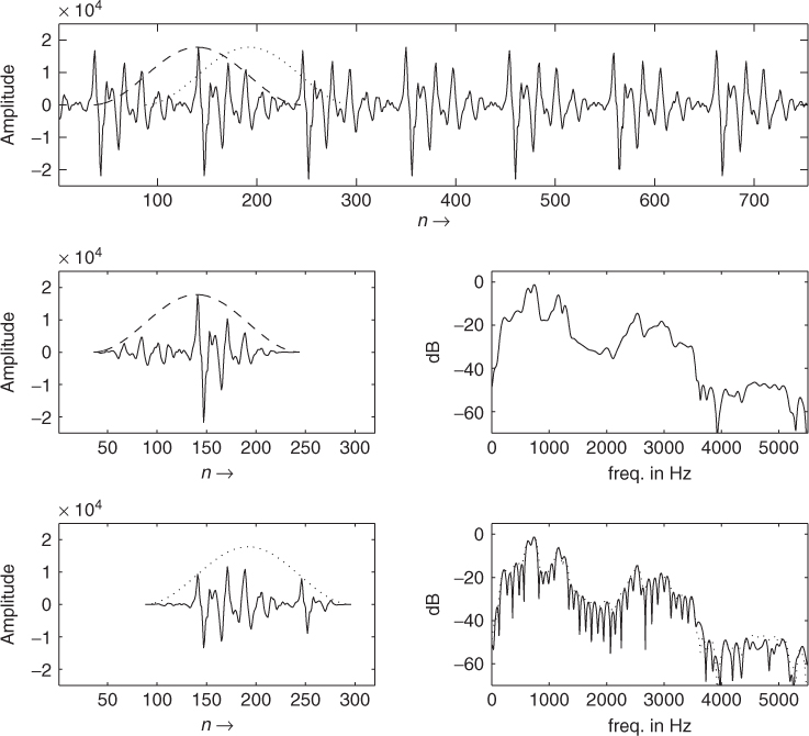
The PSOLA algorithm can be conveniently used for pitch shifting a voice sound maintaining the formant position, and thus the vowel identity [ML95, BJ95]. The basic idea consists of time stretching the position of pitch marks, while the segment waveform is not changed. The underlining signal model of speech production is a pulse train filtered by a time-varying filter corresponding to the vocal tract. The input segment corresponds to the filter impulse response and determines the formant position. Thus, it should not be modified. Conversely, the pitch mark distance determines the speech period, and thus should be modified accordingly. The aim of PSOLA analysis is to extract the local filter impulse response. As can be seen in Figure 6.18, the spectrum of a segment extracted using a Hanning window with a length of two periods approximates the local spectral envelope. Longer windows tend to resolve the fine line structure of the spectrum, while shorter windows tend to blur the formant structure of the spectrum. Thus if we do not stretch the segment, the formant position is maintained. The operation of overlapping the segments at the new pitch mark position will resample the spectral envelope at the desired pitch frequency. When we desire a pitch shift by a factor β, defined as the ratio of the local synthesis pitch frequency to the original one ![]() , the new pitch period will be given by
, the new pitch period will be given by ![]() , where in this case
, where in this case ![]() because time is not stretched.
because time is not stretched.
Figure 6.18 Spectrum of segments extracted from a vowel /a/ by using a Hanning window 4 (dotted line), 2 (solid line) and 1 (dashed line) pitch periods long, respectively. It can be noticed that the solid line approximates the local spectral envelope.
The analysis algorithm is the same as that previously seen for PSOLA time stretching in Section 6.3.3 (see Figure 6.8). The synthesis algorithm is modified (see Figure 6.19) according to the following steps:
- For every synthesis pitch mark
 :
:
1. Choice of the corresponding analysis segment i (identified by the time mark ti) minimizing the time distance ![]() .
.
2. Overlap and add the selected segment. Notice that some input segments will be repeated for β > 1 (higher pitch) or discarded when β < 1 (lower pitch).
3. Determination of the time instant ![]() where the next synthesis segment will be centered, in order to preserve the local pitch, by the relation
where the next synthesis segment will be centered, in order to preserve the local pitch, by the relation
![]()
- For large pitch shifts, it is advisable to compensate the amplitude variation, introduced by the greater or lesser overlapping of segments, by multiplying the output signal by 1/β.
It is possible to combine time stretching by a factor α with pitch shifting. In this case, for every synthesis pitch mark ![]() the first step of the synthesis algorithm above presented will be modified by the choice of the corresponding analysis segment i (identified by the time mark ti), minimizing the time distance
the first step of the synthesis algorithm above presented will be modified by the choice of the corresponding analysis segment i (identified by the time mark ti), minimizing the time distance ![]() .
.
Figure 6.19 PSOLA: synthesis algorithm for pitch shifting.
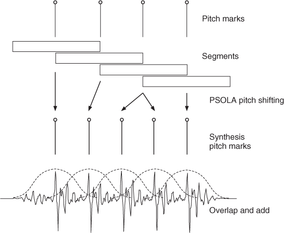
The PSOLA algorithm is very effective for speech processing and is computationally very efficient, once the sound has been analyzed, so it is widely used for speech synthesis from a database of diphones, for prosody modification, for automatic answering machines etc. For wide variation of the pitch it presents some artifacts. On the other hand, the necessity of a preliminary analysis stage for obtaining a pitch contour makes the real-time implementation of an input-signal modification difficult. Also the estimation of glottal pulses can be difficult. A solution is to place the pitch marks at a pitch synchronous rate, regardless of the true position of the glottal pulses. The resulting synthesis quality will be only slightly decreased (see, for example, Figure 6.20).
Figure 6.20 Comparison of a segment extracted in the correspondence with glottal pulse with one extracted between pitch pulses.
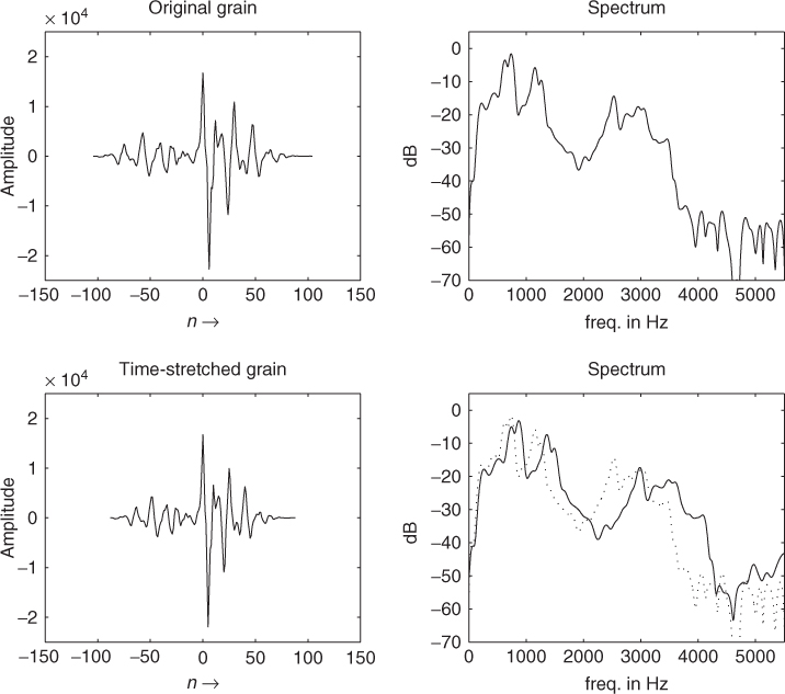
A further effect that can be obtained by a variation of PSOLA is linear scaling of formant frequencies (see Figure 6.21). In fact, we saw that the time scale of a signal corresponds to an inverse frequency scale. Thus when we perform time scaling of the impulse response of a filter, we inversely scale the frequency of formants. In PSOLA terms, this corresponds to time scaling the selected input segments before overlap and adding the synthesis step, without any change in the pitch marks calculation. To increase the frequencies of formants by a factor γ, every segment should be shortened by a factor 1/γ by resampling. For example, the average formant frequencies of female adults are about 16% higher than those of male adults, and children's formants are about 20% higher than female formants. Notice that care should be taken when the frequencies increase in order to avoid foldover. Ideally band-limited resampling should be used.
Figure 6.21 PSOLA: variation of PSOLA as linear formant scaling.
The PSOLA pitch shifter can be used to synthesize multiple voices from one real singer to create a virtual choir effect [SPLR02].
The following M-file 6.5 shows the implementation of the basic PSOLA synthesis algorithm. It is based on the PSOLA time-stretching algorithm shown in Section 6.3.3.
M-file 6.5 (psolaf.m)
function out=psolaF(in,m,alpha,beta,gamma)
% Authors: G. De Poli, U. Zölzer, P. Dutilleux
% . . .
% gamma newFormantFreq/oldFormantFreq
% . . .
% the internal loop as
tk = P(1)+1; %output pitch mark
while round(tk)<Lout
[minimum i]=min(abs(alpha*m-tk) ); % find analysis segment
pit=P(i);pitStr=floor(pit/gamma);
gr=in(m(i)-pit:m(i)+pit).*hanning(2*pit+1);
gr=interp1(-pit:1:pit,gr,-pitStr*gamma:gamma:pit);% stretch segm.
iniGr=round(tk)-pitStr;endGr=round(tk)+pitStr;
if endGr>Lout, break; end
out(iniGr:endGr)=out(iniGr:endGr)+gr; % overlap new segment
tk=tk+pit/beta;
end % end of while