
Inset types of permanent magnet bearingless motor
In the previous chapter a method for controlling radial force generation, when considering the armature reaction, was described. The radial suspension force can be controlled without interference between the components in two perpendicular axes. With the correct design of the decoupling controller and rotor, suspension force generation under torque-generating conditions can be further enhanced.
In the inset type of permanent magnet motor, the armature reaction is quite high and advantage can be taken of this to enhance the suspension force. The key is the construction of a precise and accurate decoupling controller with the identification of radial force parameters.
In this chapter an inset type of permanent magnet rotor is put forward, which has a typical salient-pole rotor design as found in permanent magnet motors, and the structure, features and a position control strategy for this motor, as well as an off-line parameter identification method, are described.
10.1 Structure and features of an inset type of permanent magnet rotor
Figure 10.1 shows an inset type of permanent magnet rotor structure. This type of rotor has q-axis saliency and the permanent magnets are mounted on the rotor iron core between the salient poles. Hence the motor q-axis magnetic permeance is larger than that of the d-axis and the features of this type rotor can be summarized as follows:
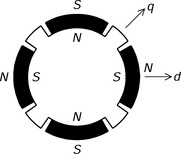
1. The magnetic permeance in the motor q-axis flux path is large; therefore, the radial suspension force can be increased by taking advantage of the armature reaction flux.
2. A reluctance torque is also generated when field-weakening the motor winding current (i.e., when the motor winding current is phase-advanced so that it is no longer on the q-axis), resulting in an increase in the torque or extended operation above the base speed.
10.2 Mutual interference between radial suspension forces
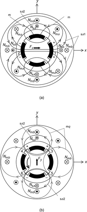
Figure 10.2(a) shows the cross section of an inset type of permanent magnet bearingless motor and illustrates the principle of radial force generation with no torque [1]. Figure 10.2(b) shows radial force generation when there is torque. If the rotor rotational position is zero then the permanent magnet field excitation Ψm is oriented as shown in Figure 10.2(a). In this instance, when suspension winding current flows in winding Nsa in the positive direction, there are two representative suspension flux paths. The first goes through the permanent magnets and the second goes through the salient rotor poles. These flux paths are denoted by Ψsa1 and Ψsa2; Ψsa1 is in the same direction across airgap section 1 as Ψm, while it is in the opposite direction across airgap section 2. Therefore a suspension force is generated in the positive x-axis direction. If there is torque generation then the q-axis motor flux Ψmq is generated so that torque is produced in a counter-clockwise direction as shown in Figure 10.2(b). During this condition, Ψmq and Ψsa2 have the same direction across airgap sections 3 and 4. However, the direction of Ψmq is reversed across airgap sections 5 and 6. As a result, a suspension force is generated in the positive y-axis direction. Hence it can be seen that suspension forces are generated in the y direction as well as the x direction when there is torque. The suspension force in the y direction depends on the magnitude of the q-axis motor flux, which varies with the motor torque condition. Therefore, it is necessary for the suspension forces to be decoupled so that the radial position regulation is insensitive to the motor torque variation.
10.3 Rotor position control strategy
The inset type of permanent magnet motor has q-axis salient poles so that the operation strategy is based upon the relationship between the suspension force and the suspension winding current in a salient-pole permanent magnet bearingless motor, which ensures that the rotor radial position control can be performed [2]. The relationship between the suspension force and the current was shown in (7.21) and the system control diagram was illustrated in Figure 7.17. In addition, the voltages at the motor winding terminals can be expressed using (7.3) in synchronously rotating coordinates, and the rotational torque is given by (7.8).
10.4 Identification of suspension force parameters
In the inset type of permanent magnet bearingless motor, the suspension force parameters λ′mM′q, and M′d are used in a decoupling controller as shown previously in Figure 7.17. In this section, an off-line measurement method for these parameters is introduced [2–5]. This method does not require magnetic suspension while measuring the parameters so that the rotor should be mechanically held and fixed at the centre position.
From the relationship between the flux linkages and the winding currents in (7.11), when the suspension d- and q-windings are open-circuit (so that the currents isd and isq are zero), the flux linkages λsd and λsq of suspension d- and q-windings become
The radial position relationship between the i- and j-axes and the x- and y-axes was written in (7.17). A similar relationship can also be defined for the flux linkages as
where λsa and λsb are the flux linkages of the suspension windings sa and sb which are fixed to the stationary coordinates. Substituting (7.17) and (10.2) into (10.1) yields
where Kf and θf were previously shown in (7.25) and (7.26) as
Hence, when the shaft is driven at constant speed, the induced voltages vsa and vsb at the terminals of the suspension windings Nsa and Nsb are
where ω is the shaft angular speed. The rotor angular position φ = ωt, so transforming vsa and vsb into the induced voltages vsu, vsv and vsw of the 3-phase suspension windings Nsu, Nsv and Nsw yields
Therefore the line-to-line voltages vsuv, vsvw and vswu can be expressed as
It is obvious from (10.8) that the induced voltages are proportional to the angular speed and rotor radial displacement. One can obtain Kf by differentiating the induced voltage with respect to the rotor radial displacement so that
where Vs is the amplitude of the induced line-to-line voltage at the suspension windings when the rotor has x displacement while the displacement in the y direction is kept zero, or vice-versa. The partial derivative equation is used for the following reasons:
1. The centre position is not easy to obtain in experiments.
2. The induced voltage is proportional to the displacement around the centre.
The force parameters λ′m, M′q and M′d can be obtained using the measurement techniques described below.
1. When imd = imq = 0, λ′m is given by (10.4):
When the motor is rotated with imd = imq = 0, the induced line-to-line voltages at the suspension winding terminals are measured with rotor eccentricity. Substituting the induced voltage derivative with respect to the rotor radial displacement and the angular speed into (10.9), the parameter λ′m can be obtained from (10.10). If the external driver is not suitable then a small motor current should be supplied.
2. When imd = 0, Kf is written in (10.4) as
Equating (10.9) and (10.11) and solving for M′q yields
When the motor is operated under torque load while imd = 0, the induced line-to-line voltages are measured with an eccentric rotor displacement. Then, substituting the induced voltage derivative, the angular speed, the q-axis current and the calculated λ′m in 1 into (10.12), one can obtain the parameter M′q.
3. Substituting (10.4) into (10.9) and solving for M′d yields
The d- and q-axis currents are provided by the controller and the induced line-to-line voltages are measured. Again, substituting the induced voltage derivative, the angular speed, the d- and q-axis currents and the calculated λ′m and M′q in 1 and 2 into (10.13), one can obtain the parameter M′d.
Figure 10.3(a,b) shows the variations in the measured induced voltage amplitudes at the suspension winding terminals with respect to the rotor radial displacement in the x direction at no torque and rated torque. The specification of a prototype machine is given in Table 10.1. The gradients of the characteristics are 1842 V/m in Figure 10.3(a) and 3279 V/m in Figure 10.3(b). The rotational speed is 3000 r/min and the d-axis current is zero. The q-axis current imq is zero in Figure 10.3(a) and 13.86 A in Figure 10.3(b). The shaft is supported by a ball bearing located in a housing so that the radial position can be fixed at any desired position. The y position is kept zero by monitoring the voltage waveforms on an oscilloscope. Derive the force parameters λ′m and M′q.
Table 10.1
Specification of an inset type machine
| Parameter | Value |
| Stator | |
| Outer diameter | 100 mm |
| Inner diameter | 50 mm |
| Rotor | |
| Outer diameter | 47 mm |
| PM | Sm-Co |
| PM thickness | 5 mm |
| Airgap length | 1.5 mm |
| Stack length | 50 mm |
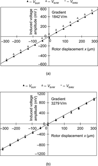
Figure 10.3 Induced voltage amplitudes at suspension winding terminals: (a) at no load; (b) under torque-loaded condition
From (10.9) and (10.10) and with no load
With a load condition, and from (10.12):
Figure 10.4 shows the relationship between the measured radial force and the suspension winding current operating at 1000 r/min, imd = 0A and imq = 13.86A. The horizontal axis is the amplitude of the suspension winding current in the 3-phase coordinate system. Derive the suspension force for unity current and compare with the measured values.
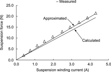
From the approximated line in Figure 10.4, the measured suspension force for unity current is 4.83 N/A. From (7.27), the theoretical suspension force F/Is3 for unity current in 3-phase coordinates is
Substituting (10.11) into (10.16) yields
Substituting the calculated parameters λ′m and M′q in Example 10.1 and imq = 13.86A into (10.17) gives F/Is3 = 4.51 N/A. Therefore the calculated value is within 7% error. This is acceptable for an off-line parameter measurement method. For more accurate parameter measurements, on-line measurements are necessary which require successful magnetic suspension.
References
[1] Hara, S., Sugitani, N., Chiba, A., Fukao, T., “Radial Forces of Salient Pole Permanent Magnet Type Bearingless Motors”. Proceedings of the 9th Symposium on Electromagnetics and Dynamics, 1997:541–546.(in Japanese)
[2] Inagaki, K., Chiba, A., Rahman, M.A., Fukao, T., “Performance Characteristics of Inset-Type Permanent Magnet Bearingless Motor Drives”. IEEE Power Engineering Society Winter Meeting WM2000 Conference Record CDROM, Singapore, January, 2000.
[3] Hiraguri, K., Chiba, A., Fukao, T., “Influence of Space Harmonics on Induced Voltages in Bearingless Motors”. Papers of Technical Meeting on Semiconductor Power Converters SPC-97-51, May 16, 1997:91–98.(in Japanese)
[4] Inagaki, K., Chiba, A., Fukao, T., “A Measurement of Radial Force Coefficient in Permanent Magnet Type Bearingless Motors”. IEE Japan, The Papers of Technical Meeting on Linear Drives LD-98–78, 1998:1–6.(in Japanese)
[5] Inagaki, K., Fujie, N., Chiba, A., Fukao, T., “A Measurement of Machine Parameters and Decoupling Control in Inset Permanent Magnet Type Bearingless Motors”. The Papers of Technical Meeting on Semiconductor Power Converters, SPC-99-48, 1999:49–56.May 17, (in Japanese)