
Design procedure and examples
In this chapter, one example of the bearingless induction motor and one example of the bearingless permanent magnet motor are introduced. In the first section, the sizes, dimensions, winding structure, inductance functions and performance figures of a bearingless induction machine with pole-specific rotor circuits are put forward and the machine is described in detail. In the following section, a bearingless permanent magnet machine, with a consequent-pole rotor, is introduced. The consequent-pole rotor machine is the most straightforward bearingless motor to initially study because rotor angular position feedback is not required for the magnetic suspension system. Also the output torque and radial force are high.
20.1 An induction type bearingless motor [1–4]
Figure 20.1 shows two cross sections of a bearingless induction motor with geometrical parameters defined for the rotor and stator iron cores. The stator has 24 slots with an outer radius of Rstyko and an inner radius of Rstyki. The rotor has 16 circular holes centred round the radius of Rbar. The outer and inner radii of the rotor iron are R and Rs respectively. In the enlarged figures, several dimensions, as indicated by Tws, Tgs, Tgd, So, SlotOpenRotor, RcIron and airgap g, are defined. Table 20.1 summarizes these parameters.
Table 20.1
| Shaft radius | Rs | 12.5 mm |
| Rotor bar centre radius | Rbar | 21 mm |
| Rotor iron outer radius | R | 24.6 mm |
| Rotor slot radius | RcIron | 2.5 mm |
| Rotor slot open width | SlotOpenRotor | 1mm |
| Airgap length | g | 0.4 mm |
| Stator inner radius | 25 mm | |
| Stator yoke inner radius | Rstyki | 40 mm |
| Stator yoke outer radius | Rstyko | 50 mm |
| Stator teeth width | Tws | 3 mm |
| Stator slot open angle | So | 3 deg |
| Stator teeth head thickness | Tgd | 1mm |
| Stator teeth neck | Tgs | 0.5 mm |
| Stack length of iron lamination | Ls | 50 mm |
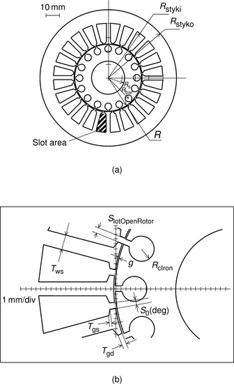
Figure 20.2 shows an enlarged figure of the stator conductor structure. Each stator slot contains a suspension and a motor winding coil-side arranged in two layers. The outer layer coil-side (in the slot bottom), as indicated by circles, is for the 4-pole motor winding; while the inner layer coil-side is for the 2-pole suspension winding. In the figure there are 12 and 3 series-connected coil-turns representing the motor and suspension winding coil-sides. Let us define the number of series-connected coil turns as N4slot and N2slot. However, in reality, one series turn is made of several parallel wires and the numbers of parallel wires (strands-in-hand) for each coil are defined as P4slot and P2slot. Let us also define the wire diameters as D4 and D2 and the total number of conductors in one slot as N4slot P4slot + N2slot P2slot. Table 20.2 summarizes winding design of the test machine. Note that N4slot and N2slot are 30 and 6 for the prototype machine and both the 2-pole and 4-pole wires have a diameter of 0.6 mm. The number of strands-in-hand is two for both windings, and the conductors are connected as shown previously in section 6.9. The area of one stator slot is 78.3 mm2 while the total cross-sectional area of all the conductors for one slot is 20.36 mm2; this is obtained from
Table 20.2
| Stator design | ||
| 2-Pole series turns per slot | N2slot | 6 turn |
| 2-Pole parallel wires | P2slot | 2 |
| 4-Pole series turns per slot | N4slot | 30 turn |
| 4-Pole parallel wires | P4slot | 2 |
| 2-Pole wire diameter | D2 | 0.6 mm |
| 4-Pole wire diameter | D4 | 0.6 mm |
| One slot area of stator | 78.3 mm2 | |
| Conductor area per slot | 20.36 mm2 | |
| Conductor slot fill factor | 0.26 | |
| 2-Pole conductor ratio | 0.17 | |
| Rotor design | ||
| Outer radius of coil end conductor | Roend | 24.11mm |
| Inner radius of coil end conductor | Riend | 12.75 mm |
| Rotor bar clearance | BarClear | 0.02 mm |
| Coil end conductor thickness | te | 3.2 mm |
| Coil end insulator thickness | ti | 3mm |
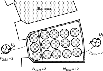
which gives a slot fill factor of 0.26. This value can be improved up to 0.3 or 0.35 with tight winding. The cross-sectional area ratio of the 2-pole coil-side with respect to the total conductor area is 0.17 which means that 17% more slot area is required when compared to the original induction motor in order to accommodate the suspension winding.
Figure 20.3(a) shows the coil end conductor structure (end-ring section) for the pole-specific rotor short circuit. The end-ring section outer radius Roend is almost equal to the rotor radius. The rotor bar radius Rc is slightly smaller than the rotor iron slot radius. The end-ring section inner radius Riend is designed so that it has a suitable width; the end-ring cross section should have the same area as the rotor bars. Four end-ring sections are required for one short circuit (which link four bars) in the 4-pole-specific rotor. In total, for a 16-slot rotor, 16 conductors are needed, which are arranged in four short circuits.
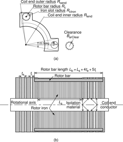
Figure 20.3(b) shows a cross-sectional view of the rotor in the axial direction. The shaft is horizontal across the centre of the section and it is surrounded by laminated silicon steel. At both the left and right ends of the rotor are the four layers of the end-ring sections, as illustrated. Two rotor bars are drawn to illustrate the connection of one rotor short circuit. The thickness of the end-ring sections is te and the thickness of the isolation material is ti. The isolation layer thickness is small since the induced voltage in the rotor circuits is low. In some cases, the isolation layer is not really needed because of the metal contact resistance – the oxidized surface of the end-ring sections providing sufficient isolation. In this test machine, the insulation ring is also used to mechanically fix the end-ring sections to the rotor. Table 20.2 lists the parameters for the rotor design.
Table 20.3 summarizes the measured inductances of the test machine. The inductance measurements were carried out before the rotor short circuits were formed so that only the laminated silicon iron was employed as the rotor. Some inductance values were measured across the whole current range to assess the influence of magnetic saturation. The flux density in a stator tooth was measured using search coils with an excitation current of 3.5A so that the tooth flux density was about 1.2 T. The excitation current was supplied at mains frequency and the inductance measurements were carried out with different rotor radial displacements. The measured inductance values were transformed into 2-phase coordinates using a 3-phase-to-2-phase transformation matrix, and the self inductances and mutual inductance derivatives M′ were obtained.
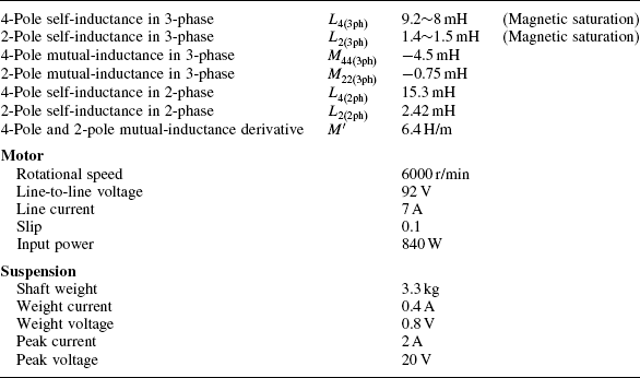
The table also shows the test results of motor and suspension characteristics at a speed of 6000 r/min. At the motor terminals, the line-to-line voltage was 92V while the input power was 840 W at a slip of 0.1 and a line current of 7A. For the magnetic suspension, two bearingless motors generated a magnetic force of 3.3 kgf to match the shaft weight. To generate a force of 3.3 kgf, a current of 0.4 A and a voltage of 0.8V were required at a frequency of 200 Hz, i.e., twice the rotational frequency. These values were measured by an FFT analyser to detect the frequency component. The peak current was 2A and the voltage was 20V. This voltage and current were required to control the vibrations caused by mechanical unbalance and misalignment. About 10 kgf of radial force can be generated by one bearingless unit within the current ratings of suspension windings.
20.2 A permanent magnet type bearingless motor [5,6]
In this section, a consequent-pole bearingless motor is described as an example of a permanent magnet type of bearingless motor. As described in Chapter 14, the consequent-pole rotor does not require rotor angular position feedback in the suspension control which makes it easier to construct.
Figure 20.4 shows the rotor and stator structures. The rotor has four permanent magnets in a laminated silicon steel core. These are identical and pre-magnetized. In this case, the magnet north poles are all on the rotor surface. They are manufactured from NeFeBr and are 5-mm thick. In the stator core there are two sets of 3-phase conductors, arranged in slots. One set is the 8-pole motor winding, N8u, N8v and N8w and the other set is the 2-pole suspension winding, N2u, N2v and N2w. The 3-phase suspension winding has been found to minimize the radial force variation with respect to rotor angular position. Since there are two 3-phase sets there are six wires connecting the bearingless unit to the inverters.
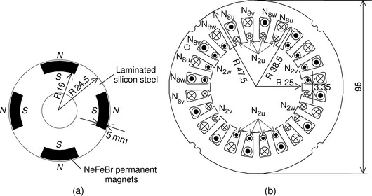
Table 20.4 summarizes the machine and winding design. The rotor radius is 24.5 mm with an axial length of 50 mm. The product D × L (diameter and the axial length) is 24.5 cm2 and the airgap length is 0.5 mm. In the winding design, the conductor slot fill factor is a rather low value of 0.27 for easy winding installation and the cross-sectional area of suspension conductors occupies 17% of the total conductor area (similar to the bearingless induction motor above).
Table 20.4
| Iron and PM design | ||
| Rotor iron outer radius | R | 24.5mm |
| Permanent magnet thickness | Lm | 5.0 mm |
| Permanent magnet arc | 45 deg | |
| PM remanent flux density | Br | 1.28 T |
| Airgap length | g | 0.5 mm |
| Stator inner radius | 25 mm | |
| Stator yoke inner radius | Rstyki | 38.5 mm |
| Stator outer radius | Rstyko | 47.5mm |
| Stator teeth width | Tws | 3.35 mm |
| Stack length of iron lamination | Ls | 50 mm |
| Winding design | ||
| 2-Pole series turns per slot | N2slot | 10 turn |
| 2-Pole parallel wires | P2slot | 1 |
| 8-Pole series turns per slot | N8slot | 25 turn |
| 8-Pole parallel wires | P8slot | 2 |
| 2-Pole wire diameter | D2 | 0.6 mm |
| 8-Pole wire diameter | D8 | 0.6 mm |
| One stator slot area | 63.4mm2 | |
| Conductor slot fill factor | 0.27 | |
| 2-Pole conductor ratio | 0.17 |
Figure 20.5 shows a system block diagram of the test machine. In the suspension controller, the radial positioning is detected by displacement sensors and compared with the references. The PID controllers generate radial force commands and, using these commands, the current commands I*x and I*y are generated. Instantaneous 3-phase winding current commands are generated by a 2-phase-to-3-phase transformation, and a current-regulated PWM voltage-source inverter provides the 3-phase currents for the suspension windings.
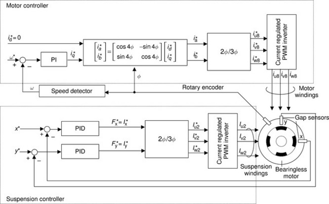
In the motor controller, the rotor angular position is detected by a rotary encoder which also provides speed feedback. The speed is compared with the speed command so that a motor current command is generated. From the d- and q-axis current commands, 2-phase currents are generated for the 8-pole motor operation. The 3-phase current commands are fed forward to a current-regulated PWM voltage-source inverter to provide the motor currents. It is possible to have sensorless angular position operation since the rotary encoder is needed only for the motor drive.
In constructing a test machine, special attention should be paid to the permanent magnets. Inserting them into the rotor core is not straightforward if they are pre-magnetized rare-earth magnets since there is always a strong attractive force between the rotor core and the permanent magnets; and sintered material is quite brittle. Also, inserting the rotor into the stator core can be tricky, again because of the attractive force between the rotor and stator which can be quite significant. Once inserted, the rotor should be fixed using touch-down bearings so that the shaft is movable within a radius of only about 0.1 mm from the centre position.
The drive inverter should be carefully designed so that there is fast-acting circuit protection for the occasional transient over-current. The current needs to be limited to prevent the permanent magnets from being irreversibly demagnetized (though sintered rare-earth magnets are often very difficult to magnetize and demagnetize – hence the fabrication of the motor with fully magnetized magnets).
Table 20.5 summarizes the measured test data. The voltage, current and power were measured by a digital power meter at the rated load point. The shaft torque is reasonable for the machine dimensions although the efficiency is rather low; however, it can be improved by increasing the slot fill factor and by PM thickness optimization. At the suspension winding terminals, the voltage, current and power were measured at two operating points – one is the zero torque point while the other is the full-load torque point. The radial force was 128 and 96N, while the radial force density DL is 0.53 and 0.4kgf/cm2 and the VA ratio and power ratio between the suspension and motor windings are only 0.08 and 0.03 at zero and full torque, respectively.
Table 20.5
| Motor | |
| Rotational speed | 4000 r/min |
| Line-to-line voltage | 143V |
| Line current | 4.8A |
| Input power | 926W |
| Shaft torque | 1.89 Nm |
| Efficiency | 85.6% |
| Total power factor | 0.721 |
| Suspension | |
| At no torque (Iq = 0A) | |
| Radial force | 128 N |
| Line-to-line voltage | 25.0V |
| Line current | 2.47A |
| Input power | 30.3W |
| At full torque (Iq = 8A) | |
| Radial force | 96N |
| Line-to-line voltage | 25.9 V |
| Line current | 2.07A |
| Input power | 30.3W |
References
[1] Takamoto, Y., Chiba, A., Fukao, T., “Test Results on a Prototype Bearingless Induction Motor with Five-Axis Magnetic Suspension”. Proceedings of 1995 International Power Electronics Conference (IPEC – Yokohama ’95), Vol. 1, 1995:334–339. [April 7, Pacifico Yokohama].
[2] Chiba, A., Furuichi, R., Aikawa, Y., Shimada, K., Takamoto, Y., Fukao, T., “Stable Operation of Induction-Type Bearingless Motors Under Loaded Conditions”. IEEE Transaction on IA, Vol. 33, No. 4, 1997:919–924. [July/August].
[3] Chiba, A., Yoshida, K., Fukao, T., “Transient Response of Revolving Magnetic Field in Induction type Bearingless Motors with Secondary Resistance Variations”. International Symposium on Magnetic Bearings (ISMB ’98), 1998:461–475. [August 7, Boston, USA].
[4] Suzuki, T., Chiba, A., Rahman, M.A., Fukao, T., “An Air-Gap-Flux-Oriented Vector Controller for Stable Operation of Bearingless Induction Motors”. IEEE Transaction on IA, Vol. 36, No. 4, 2000:1069–1076. [July/August].
[5] Takenaga, T., Kubota, Y., Chiba, A., Fukao, T., “A Principle and a Design of a Consequent-Pole Bearingless Motor”. ISMB-8, 2000:259–264. [August, at Mito].
[6] Kubota, Y., Takenaga, T., Chiba, A., Fukao, T., “Consequent-Pole Type Bearingless Motors”. IEE Japan, The Papers of Joint Technical Meeting on Semiconductor Power Converter and Industry Electric and Electronic Application, SPC-01-102, 2001:49–54.November 8, at Ashikaga (in Japanese)