
Chapter 14
Interpreting Schematics
IN THIS CHAPTER
![]() Understanding the role of schematics
Understanding the role of schematics
![]() Getting to know the most common symbols
Getting to know the most common symbols
![]() Using (and not abusing!) component polarity
Using (and not abusing!) component polarity
![]() Diving into some specialized components
Diving into some specialized components
![]() Having fun with schematics from around the world
Having fun with schematics from around the world
Imagine driving cross-country without a road map. Chances are, you’d get lost along the way and end up driving in circles. Road maps exist to help you find your way. You can use the equivalent of road maps for building electronic circuits as well. They’re called schematic diagrams, and they show you how all the parts of the circuits are connected. Schematics show these connections with symbols that represent electronic parts and lines that show how you attach the parts.
Although not all electronics circuits you encounter are described in the form of a schematic, many are. If you’re serious at all about studying electronics, (sooner or later) you need to understand how to read a schematic. Not to worry! The language of schematics isn’t all that hard to learn. Most schematic diagrams use only a handful of symbols for components, such as resistors, capacitors, and transistors.
This chapter tells you all you really need to know to read almost any schematic diagram you come across.
What’s a Schematic and Why Should I Care?
A schematic is a circuit diagram that shows all the components of a circuit, including power supplies and their connections. When you’re reading a schematic, the most important things to focus on are the connections because the positioning of components in a schematic diagram does not necessarily correspond to the physical layout of components in a constructed circuit. (In fact, for complex circuits, it’s unlikely that the physical circuit layout reflects the positioning shown in the schematic. Complex circuits often require separate layout diagrams, sometimes known as artwork.)
 Schematics use symbols to represent resistors, transistors, and other circuit components, and lines to show connections between components. By reading the symbols and following the interconnections, you can build the circuit shown in the schematic. Schematics can also help you understand how a circuit operates, which comes in handy when you’re testing or repairing the circuit.
Discovering how to read a schematic is a little like learning a foreign language. On the whole, you'll find that most schematics follow fairly standard conventions. However, just as many languages have different dialects, the language of schematics is far from universal. Schematics can vary depending on the age of the diagram, its country of origin, the whim of the circuit designer, and many other factors.
 This book uses conventions commonly accepted in North America. But to help you deal with the variations that you may encounter, I include some other conventions, such as those commonly used in Europe.
Seeing the Big Picture
There’s an unwritten rule in electronics about how to orient certain parts of a circuit schematic — especially when drawing diagrams of complex circuits. Batteries and other power supplies are almost always oriented vertically, with the positive terminal on top. In complex schematics, power supplies are split between two symbols (as you will see later), but the positive terminal is usually shown at the top of the schematic (sometimes extending across a horizontal line, or rail) and the negative terminal appears at the bottom (sometimes along a rail). Inputs are commonly shown on the left and outputs on the right.
Many electronic systems, such as the radio-receiver system shown in Figure 14-1, are represented in schematics by several stages of circuitry — even though the system really consists of one large, complex circuit. The schematic for such a system shows the sub-circuits for each stage in a left-to-right progression (for instance, the tuner sub-circuit on the left, the detector in the middle, and the amplifier on the right), with the output of the first stage feeding into the input of the second stage, and so forth. Organizing schematics in this way helps make complex circuits more understandable.

FIGURE 14-1: Block diagram representing a radio-receiver system.
It’s all about your connections
In all schematics, simple or complex, components are arranged as neatly as possible, and connections in a circuit are drawn as lines, with any bends shown as 90° angles. (No squiggles or arcs allowed!) It’s absolutely critical to understand what all the lines in a schematic really mean — and their meaning is not always obvious.
The more complex the schematic, the more likely it is that some lines will crisscross each other (due to the 2-D nature of schematic drawings). You need to know when crossed lines represent an actual wire-it-together connection and when they don’t. Ideally, a schematic will clearly distinguish connecting and nonconnecting wires like this:
- A break or a loop (think of it as a bridge) in one of the two lines at the intersection indicates wires that should not be connected.
- A dot at the intersection of two lines indicates that the wires should be connected.
You can see some common variations in Figure 14-2.
 This method of showing connections isn’t universal, so you have to figure out which wires connect and which don’t by checking the drawing style used in the schematic. If you see an intersection of two lines without a dot to positively identify a real connection, you simply cannot be sure whether the wires should be connected or not. It’s best to consult with the person who drew the schematic to determine how to interpret the crisscrossing lines.
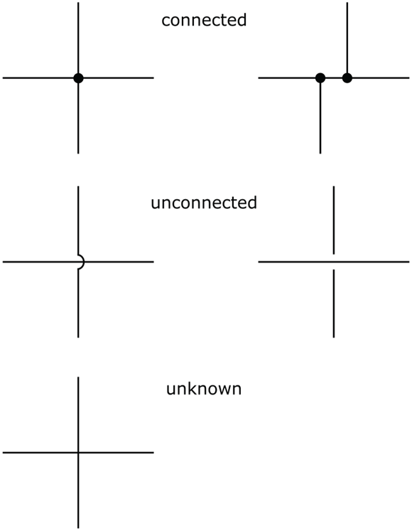
FIGURE 14-2: You may encounter a number of variations in how a schematic shows connections and nonconnections.
To physically implement the connections shown in a schematic, you typically use insulated wires or thin traces of copper on a circuit board. Most schematics don’t make a distinction about how you connect the components; that connection is wholly dependent on how you choose to build the circuit. The schematic’s representation of the wiring merely shows you the connections that must be made between components.
Looking at a simple battery circuit
Figure 14-3 shows a simple DC circuit with a 1.5 V battery connected to a resistor labeled R1. The positive side of the battery (labeled +) is connected to the lead on one side of the resistor; the negative side of the battery is connected to the lead on the other side of the resistor. With these connections made, current flows from the positive terminal of the battery through the resistor, and back to the negative terminal of the battery.
In schematics, current is assumed to be conventional current, which is described as the flow of positive charges, traveling in a direction opposite to that of real electron flow. (For more about conventional current and electron flow, see Chapter 3.)
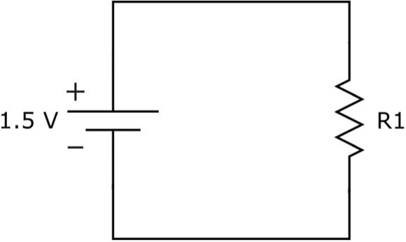
FIGURE 14-3: A simple schematic shows the connections between a battery and a resistor.
Recognizing Symbols of Power
Power for a circuit can come from an alternating current (AC) source, such as the 120 VAC (volts AC) outlet in your house or office (line power), or a direct current (DC) source, such as a battery or the low-voltage output from a wall transformer. DC supplies can be positive or negative with respect to the zero-volt reference (known as common ground, or simply common) in a circuit. Figure 14-4 shows various symbols used to represent power and ground connections. These symbols are discussed more fully in the next two subsections.

FIGURE 14-4: Symbols for power and ground.
Figuring out the various power connections in a complex schematic is sometimes a task unto itself. This section aims to clear things up a bit. As you read through this section, refer to Figure 14-4 to see the symbols as they’re discussed.
Showing where the power is
DC power supplies are shown in one of two ways:
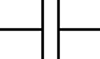
Battery or solar-cell symbol: Each of the battery symbols in Figure 14-4 represents a DC source with two leads. Technically, the battery symbol that includes two parallel lines (the first symbol for battery) represents a single electrochemical cell; the symbol with multiple pairs of lines (the second symbol) represents a battery (which consists of multiple cells).
Many schematics (including those in this book) use the symbol for a cell to represent a battery.Each symbol includes a positive terminal (indicated by the larger horizontal line) and a negative terminal. The polarity symbols (+ and –) and nominal voltage are usually shown next to the symbol. The negative terminal is often assumed to be at 0 volts, unless clearly distinguished as different from the zero-voltage reference (known as common ground and detailed later in this chapter). Conventional current flows out of the positive terminal and into the negative terminal when the battery is connected in to a complete circuit.
- Split DC power and ground symbols: To simplify schematics, a DC power supply is often shown using two separate symbols. These symbols are a small circle at the end of a line representing one side of the supply, with or without a specific voltage label, and the symbol for ground (vertical line with three horizontal lines at the bottom) representing the other side of the supply, with a value of 0 volts. In complex circuits with multiple connections to power, you may see the positive side of the supply represented by a rail labeled +V extending across the top of the schematic. These split symbols that represent power supplies are used to eliminate a lot of (otherwise confusing) wire connections in a schematic.
The circuit shown in Figure 14-3 can also be drawn using separate symbols for power and ground, as in Figure 14-5. Note that the circuit in Figure 14-5 is, in fact, a complete circuit.
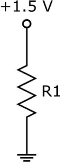
FIGURE 14-5: A simpler way to show the connections between a battery and a resistor.
Many DC circuits use multiple DC power supplies, such as +5 VDC (volts DC), +12 VDC, and even –5 VDC or –2 VDC, so the voltage-source symbols in the schematics are usually labeled with the nominal voltage. If a schematic doesn’t specify a voltage, you’re often (but not always!) dealing with 5 VDC. And remember: Unless otherwise specifically noted, the voltage in a schematic is almost always DC, not AC.
 Some circuits (for instance, some op-amp circuits, which are discussed in Chapter 11) require both positive and negative DC power supplies. You'll often see the positive supply represented by an open circle labeled +V and the negative supply represented by an open circle labeled –V. If the voltages are not specified, they may be +5 VDC and –5 VDC. Figure 14-6 shows how these power supply connection points are really implemented.

FIGURE 14-6: Some circuits require positive and negative power supplies.
An AC power supply is usually represented by a circle with two leads, either with or without a waveform shape and polarity indicators:
- Circle containing waveform: A squiggly line or other shape inside an open circle represents one cycle of the alternating voltage produced by the power supply. Usually, the source is a sine wave, but it could be a square wave, a triangle wave, or something else.
- Circle with polarity: Some schematics include one or both polarity indicators inside or outside the open circle. Polarity indicators are just for reference purposes, so you can relate the direction of current flow to the direction of voltage swings.
Power for a circuit can come from an AC source, such as the 120 VAC outlet in your house or office (such circuits are called line-powered). You typically use an internal power supply to step down (or lower) the 120 VAC and convert it to DC. This lower-voltage DC power is then delivered to the components in your circuit. If you’re looking at a schematic for a DVD player or some other gadget getting its power from a wall outlet, that schematic probably shows both AC and DC power.
Marking your ground
Ready for some electronics schematic double-talk? When it comes to labeling ground connections in schematics, it’s common practice to use the symbol for earth ground (which is a real connection to the earth) to represent the common ground (the reference point for zero volts) in a circuit. (Chapter 3 details these two types of grounds.) More often than not, the “ground” points in low-voltage circuits are not connected to earth ground; instead, they’re tied to each other — hence the term common ground (or simply common). Any voltages labeled at specific points in a circuit are assumed to be relative to this common ground. (Remember, voltage is really a differential measurement between two points in a circuit.)
So what symbol should really be used for ground points that are not truly connected to the earth? It’s the symbol labeled chassis ground. Common ground is sometimes called chassis ground because in older equipment, the metal chassis of the device (hi-fi, television, or whatever) served as the common ground connection. Using a metal chassis for a ground connection is not as common today, but the term is still often used.
You may also see the symbol for signal ground used to represent a zero-volt reference point for signals (information-carrying waveforms) carried by two wires. One wire is connected to this reference point and the other wire carries a varying voltage representing the signal. Again, in many schematics, the symbol for earth ground is used instead.
In this book, I use only the schematic symbol for earth ground because most schematics you see these days use that symbol.
As you can see in Figure 14-7, a schematic may show the ground connections in a number of ways:
- No ground symbol: The schematic can show two power wires connected to the circuit. In a battery-powered circuit, common ground is assumed to be the negative terminal of the battery.
- Single ground symbol: The schematic shows all the ground connections connected to a single point. It doesn’t often show the power source or sources (for instance, the battery), but you should assume that ground connects to the positive or negative DC power sources (refer to Figure 14-6).
- Multiple ground symbols: In more complex schematics, it's usually easier to draw the circuit with several ground points. In the working circuit, all these ground points connect together.

FIGURE 14-7: Different ways to represent a circuit’s common ground connections.
Labeling Circuit Components
You can find hundreds of symbols for electronic components out there, because there are hundreds of component types to depict. Fortunately, you probably encounter only a small number of these symbols in schematics for hobby electronics projects.
Along with the circuit symbol for a particular electronic component, you may see additional information to help uniquely identify the part:
- Reference ID: An identifier, such as R1 or Q3. The convention is to use one or more letters to represent the type of component, and a numerical suffix (sometimes subscripted) to distinguish one particular component from others of the same type. The most common type designators are R for resistor, C for capacitor, D for diode, L for inductor, T for transformer, Q for transistor, and U or IC for integrated circuit.
- Part number: Used if the component is standard (as with a transistor or an integrated circuit) or you have a manufacturer’s customer product part. For example, a part number may be something like 2N2222 (that’s a commonly used transistor) or 555 (a type of IC used in timing applications).
- Value: Component values are sometimes shown for passive parts, such as resistors and capacitors, that don’t go by conventional part numbers. For example, when indicating a resistor, the value (in ohms) could be marked beside the resistor symbol or the reference ID. Most often, you’ll see just the value without a label for the unit of measurement (ohms, microfarads, and so on). Normally resistor values are assumed to be in ohms, and capacitor values are assumed to be in microfarads.
- Additional information: A schematic may include additional specifics about one or more components, such as the wattage for a resistor when it isn’t your typical 1/4- or 1/8-watt value. If you see 10W next to a resistor value, you know you need a power resistor.
Many schematics show only the reference ID and the circuit symbol for each component, and then include a separate parts list to provide the details of part numbers, values, and other information. The parts list maps the reference ID to the specific information about each component.
Analog electronic components
Analog components control the flow of continuous (analog) electrical signals. Table 14-1 shows the circuit symbols used for basic analog electronic components. The third column in the table provides the chapter reference in this book where you can find detailed information about the functionality of each component.
TABLE 14-1 Symbols for Analog Components
Component |
Symbol |
Chapter |
Resistor |
|
|
Variable resistor (potentiometer) |
|
|
Photoresistor (photocell) |
|
|
Capacitor |
|
|
Polarized capacitor |
|
|
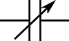
Variable capacitor |
|
|
Inductor |
|
|
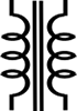
Air core transformer |
|
|
Solid core transformer |
|
|
Crystal |
|
|
NPN (bipolar) transistor |
|
|
PNP (bipolar) transistor |
|
|
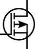
N-channel MOSFET |
|
|
P-channel MOSFET |
|
|
Phototransistor (NPN) |
|
|
Phototransistor (PNP) |
|
|
Standard diode |
|
|
Zener diode |
|
|
Light-emitting diode (LED) |
|
|
Photodiode |
|
|
Operational amplifier (op amp) |
|


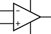
The circuit symbol for an op amp represents the interconnection of dozens of individual components in a nearly complete circuit (power is external to the op amp). Schematics always use a single symbol to represent the entire circuit, which is packaged as an integrated circuit (IC). The circuit symbol for an op amp is commonly used to represent many other amplifiers, such as an LM386 audio power amplifier.
Digital logic and IC components
Digital electronic components, such as logic gates, manipulate digital signals that consist of just two possible voltage levels (high or low). Inside each digital component is a nearly complete circuit (power is external), consisting of individual transistors or other analog components. Circuit symbols for digital components represent the interconnection of several individual components that make up the circuit’s logic. You can build the logic from scratch or obtain it in the form of an integrated circuit. Logic ICs usually contain several gates (not necessarily all of the same type) sharing a single power connection.
Figure 14-8 shows the circuit symbols for individual digital logic gates. You can find detailed information about the functionality of each logic gate in Chapter 11.

FIGURE 14-8: Symbols for logic gates.
Some schematics show individual logic gates; others show connections to the full integrated circuit, represented by a rectangle. You can see an example of each approach in Figure 14-9.
The 74HC00 IC shown in Figure 14-9 is a CMOS quad 2-input NAND gate. In the top circuit diagram, each NAND gate is labeled 1/4 74HC00 because it is one of four NAND gates in the IC. (This type of gate labeling is common in digital circuit schematics.) Note that the fourth NAND gate is not used in this particular circuit (which is why pins 11, 12, and 13 are not used). Whether the schematic uses individual gates or an entire IC package, it usually notes the external power connections. If it doesn’t, you have to look up the pinout of the device on the IC datasheet to determine how to connect power. (For more about pinouts and datasheets, see Chapter 11.)

FIGURE 14-9: Two different schematic representations of the same circuit.
You’ll find many more digital ICs other than those containing just logic gates. You’ll also find linear (analog) ICs that contain analog circuits and mixed-signal ICs that contain a combination of analog and digital circuits. Most ICs — except for op amps — are shown the same way in schematics: as a rectangle, labeled with a reference ID (such as IC1) or the part number (such as 74CH00), with numbered pin connections. The function of the IC is usually determined by looking up the part number, but the occasional schematic may include a functional label, such as one shot.
Miscellaneous components
Figure 14-10 shows the symbols for switches and relays. Refer to Chapter 4 for detailed information on each of these components.

FIGURE 14-10: Symbols for switches and relays.
Figure 14-11 shows the symbols for various input transducers (sensors) and output transducers. (Some of these symbols are cross-referenced in Table 14-1.) You can read about most of these components in Chapter 12, and you can read about LEDs in Chapter 9.

FIGURE 14-11: Symbols for input and output transducers.
Some circuits accept inputs from and send outputs to other circuits or devices. Schematics often show what looks like a loose wire leading into or out of the circuit. Usually it’s labeled something like signal input, or input from doodad #1, or output so you know you’re supposed to connect something up to it. (You connect one wire of the signal to this input point and the other to signal ground.) Other schematics may show a symbol for a specific connector, such as a plug and jack pair, which connect an output signal from one device to the input of another device. (Chapter 12 provides a closer look.)
Figure 14-12 shows a few of the ways input and output connections to other circuits are shown in schematics. Symbols for input/output connections can vary greatly among schematics. The symbols used in this book are among the most common. Although the exact style of the symbol may vary from one schematic to the next, the idea is the same: The symbol is telling you to make a connection to something external to the circuit.

FIGURE 14-12: Symbols for connections to other circuits.
Knowing Where to Take Measurements
You may run across a schematic or two that include symbols for test instruments, such as a voltmeter (which measures voltage), an ammeter (which measures current), or an ohmmeter (which measures resistance). (As Chapter 16 explains, a multipurpose multimeter can function as any of these meters — and more.) You may see these symbols in schematics on educational websites or in documents designed for educational purposes. They point out exactly where to place your meter’s leads to take the measurement properly. (The abbreviation TP, for test point, is often used to indicate where to take a measurement.)
When you see one of the symbols shown in Figure 14-13 in a schematic, remember that it represents a test instrument — not some newfangled “vulcanistor” or other electronic component you’ve never heard of before.

FIGURE 14-13: Symbols for common test instruments.
Exploring a Schematic
Now that you’re familiar with the ABCs of schematics, it’s time to put it all together and walk through each part of a simple schematic. The schematic shown in Figure 14-14 shows the LED flasher circuit used in Chapter 17. This circuit controls the on/off blinking of an LED, with the blinking rate controlled by turning the knob of a potentiometer (variable resistor).

FIGURE 14-14: The schematic and parts list used for the LED flasher project in Chapter 17.
Here’s what this schematic is saying:
- At the heart of the schematic is IC1, an 8-pin 555 timer IC, with all eight pins connecting to parts of the circuit. Pins 2 and 6 are connected together.
- The circuit is powered by a 9-volt power supply, which can be a 9 V battery.
- The positive terminal of the power supply is connected to pins 4 and 8 of IC1, and to one fixed lead and the variable contact (wiper) lead of R1, which is a variable resistor (potentiometer).
- The negative terminal of the power supply (shown as the common ground connection) is connected to pin 1 of IC1, to the negative side of capacitor C1, to capacitor C2, and to the cathode (negative side) of the LED.
- R1 is a potentiometer with one fixed lead connected to pin 7 of IC1 and to resistor R2, and both the other fixed lead and the wiper lead connected to the positive battery terminal (and to pins 4 and 8 of IC1).
- R2 is a fixed resistor with one lead connected to pin 7 of IC1 and to one fixed lead of R1, and the other lead connected to pins 2 and 6 of IC1 and the positive side of capacitor C1.
- C1 is a polarized capacitor. Its positive side is connected to R2 and to pins 2 and 6 of IC1, and its negative side is connected to the negative battery terminal (as well as to pin 1 of IC1, capacitor C2, and the cathode of the LED).
- C2 is a nonpolarized capacitor connected on one side to pin 5 of IC1 and on the other side to the negative battery terminal (as well as the negative side of capacitor C1, pin 1 of IC1, and the cathode of the LED).
- The anode (positive side) of the LED is connected to resistor R3 and the cathode of the LED is connected to the negative battery terminal (as well as to the negative side of capacitor C1, capacitor C2, and pin 1 of IC1).
- R3 is a fixed resistor connected between pin 3 of IC1 and the anode of the LED.
- Finally, the output shown at pin 3 of IC1 can be used as a signal source (input) for another stage of circuitry.
Each item in the walk-through list just given focuses on one circuit component and its connections. Although the list does mention the same connections multiple times, that’s consistent with good practice; it pays to check and double-check your circuit connections by making sure each lead or pin of each individual component is connected correctly. (Ever hear the rule of thumb “measure twice, cut once”? Well, the same principle applies here.) You can’t be too careful when you’re connecting electronic components.
Alternative Schematic Drawing Styles
The schematic symbols in this chapter belong to the drawing style used in North America (particularly in the United States) and in Japan. Some countries — notably European nations as well as Australia — use somewhat different schematic symbols. If you’re using a schematic for a circuit not designed in the United States or Japan, you need to do a wee bit o’ schematic translation to understand all the components.
Figure 14-15 shows a sampling of schematic symbols commonly used in the United Kingdom and other European nations. Note the obvious differences in the resistor symbols, both fixed and variable.

FIGURE 14-15: Schematic symbols used for circuits designed in Europe.
This style organizes its symbols differently from the American style. In the United States, you express resistor values over 1,000 Ω in the form of 6.8k or 10.2k, with the lowercase k following the value. The European schematic style eliminates the decimal point. Typical of schematics you’d find in the United Kingdom are resistor values expressed in the form 6k8 or 10k2. This style substitutes the lowercase k (which stands for kilohms, or thousands of ohms) for the decimal point.
You may encounter a few other variations in schematic drawing styles, but all are fairly self-explanatory and the differences are not substantial. After you learn how to use one style of drawing, the others come relatively easily.