6 Modeling and Simulation of Timing Behavior with the Timing Definition Language
Josef Templ, Andreas Naderlinger, Patricia Derler, Peter Hintenaus, Wolfgang Pree and Stefan Resmerita
CONTENTS
6.2 Timing Definition Language
6.2.1.1 Time and Value Determinism
6.2.1.3 Transparent Distribution
6.2.2.5 Asynchronous (= Event-Triggered) Activities
6.3 TDL Integration with MATLAB® and Simulink®
6.3.1 Application Developer’s Perspective
6.3.1.1 Extension of the TDL Toolchain for MATLAB® and Simulink®
6.3.1.4 Platform Mapping and Code Generation
6.3.2 Implementation Perspective
6.3.2.1 Resolving Data Dependencies
6.4 TDL Integration With Ptolemy II
6.5 Comparison between the Simulink® and the Ptolemy II Integration
6.1 Introduction
Traditional development of software for embedded systems is highly platform specific. Exploiting a specific platform enables reducing cost of hardware to a minimum, whereas high development costs of software are considered acceptable in the case of large quantities of devices being sold. Nowadays, with ever more powerful processors in the low-cost range, we observe even more of a shift of functionality from hardware to software and a general tendency toward more ambitious requirements. Modern cars or airplanes, for example, contain dozens of the so-called electronic control units interconnected by multiple buses and are driven by several million lines of code. To cope with the increased complexity of the embedded software, a platform-independent “high-level” programming style becomes mandatory, as testing alone can never identify all the errors. In particular, in the case of safety-critical real-time software, this applies not only to functional aspects but to the temporal behavior of the software as well. Dealing with time, however, is not covered at all by any of the existing high-level imperative languages. Simulation environments that offer delay blocks allow at best the approximation of the simulated behavior to the behavior on the execution platform.
One reason is that execution and communication times related to computational tasks of an application can have a substantial influence on the application behavior that is unaccounted for in high-level models [1]. Consequently, the implementation of a model on a certain execution platform may violate requirements that are proved to be satisfied in the model. Explicitly considering execution times at higher levels of abstractions has been proposed as a way to achieve satisfaction of real-time properties [2]. One promising direction in this respect is the logical execution time (LET) [3].
This chapter presents the explicit specification of the timing behavior using the LET-based notation called Timing Definition Language (TDL). TDL is under active, commercially supported development [4]. As simulation is widely used in industry for testing and validation of complex systems (e.g., Ref. [5]), it is important to be able to simulate TDL-based systems. Thus, we describe how TDL has been integrated with two distinctly different simulation environments, that is, MATLAB® and Simulink® [6] from MathWorks® and Ptolemy [7], an open source environment developed at the University of California at Berkeley. Where MATLAB and Simulink is treated as yet another execution platform, Ptolemy is more closely aligned with TDL principles and so offers simulation capabilities that allow a more straightforward integration of TDL. We chose these two simulation environments to demonstrate two quite different approaches for simulating TDL-based systems.
6.2 Timing Definition Language
The TDL [8] at its core follows the time-triggered programming model [3,9]. In a time-triggered system, all activities are triggered only by the ticks of a single global clock. To increase the range of applicability, TDL also supports a limited form of event-triggered programming, which allows, for example, responding to hardware interrupts.
6.2.1 TDL Properties
TDL programs that only rely on the time-triggered features exhibit the following properties by construction.
6.2.1.1 Time and Value Determinism
Value determinism means that a program provides the same outputs if it is provided with the same inputs. Time determinism means that a program provides the outputs at the same times if it is provided with the inputs at the same times, where all times are relative to the program start. TDL aims for both time determinism and value determinism. Thus, a TDL program provides the same outputs at the same times if it is provided with the same inputs at the same times. In other words, the chronologically ordered sequence of outputs (time plus values) of a TDL program, which is also referred to as the observable behavior of a program, is deterministic and platform-independent.
6.2.1.2 Portability
TDL programs represent a platform-independent description of the timing behavior of an application. Everything that is platform specific, for example, accessing sensors or actuators, is defined outside the TDL program. TDL programs behave exactly the same independent of the underlying CPU, network bandwidth, or operating system. Even when simulating a TDL application, for example, under MATLAB and Simulink, the application exhibits the same behavior.
6.2.1.3 Transparent Distribution
Since TDL abstracts from the execution platform, a TDL application shows the same observable behavior in the case of a distributed system as on a single-node system. Thus, the fact that a distributed system is used as an execution platform is transparent. It is the task of the TDL compiler to generate a suitable network communication schedule for maintaining the observable behavior of the application [10].
6.2.1.4 Time Safety
The TDL compiler provides a time safety check, which guarantees that a program behaves as expected for a particular target platform given that the worst case execution times for the tasks to be executed are known for that platform. In the case of a distributed platform, the compiler also guarantees that the network communication preserves the expected observable behavior of the application.
6.2.1.5 Compositionality
A TDL program consists of a set of so-called modules. All modules are executed in parallel, and the data flow between modules is handled by the TDL runtime system. Adding another module to the application does not change the observable behavior of the previously existing modules.
6.2.2 TDL Language Constructs
In the sequel, we introduce the individual TDL language constructs informally. For more details including a formal grammar, please refer to the TDL Language Specification [8].
6.2.2.1 Modules
At the outermost level, a TDL application consists of a set of modules[35]. Two modules can either be independent, that is, they share no data, or cooperating. Cooperating modules exchange data through ports. Statically, a module provides a namespace. Dynamically, modules are executed in parallel—possibly on different nodes in a distributed system. All modules share a common clock, which, in the case of a distributed execution platform, has to be distributed to the individual nodes of the platform. A module may encapsulate a finite state machine (FSM), where the states are denoted as modes. In a mode, the temporal aspects of all activities are defined.
6.2.2.2 Ports
Data flow within a single TDL module, between multiple modules, and between a TDL module and the physical environment is exclusively based on ports. A port is a typed variable that is accessed (read or written) at specific time instances only. Sensor and actuator ports (sensors and actuators for short) are the only means for a TDL module to communicate with the environment. A sensor declaration defines a typed read-only variable to represent a particular value in the physical environment and provides input to the TDL application. An actuator declaration is an initialized and typed write-only variable that influences a particular value in the physical environment and provides output from the TDL application to the environment. The access to the hardware is performed by user-provided setter and getter functions that are external to TDL.
6.2.2.3 Tasks
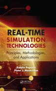
A task is the computational unit in TDL. It defines a namespace for input, output, and state ports. Each task is associated with a task function, that is, a stateless piece of code without any synchronization points. A single invocation of a task at runtime creates a task activation. A task activation lasts for a strictly positive amount of time that starts at the release time (the time when the task activation is released) and ends at the termination time (the time when the task activation is terminated). The time between these two instants is called the logical execution time (LET) of the task activation (Figure 6.1). At the release time, the input ports of the corresponding task are updated with the values read from the output ports of other tasks and sensors that have been passed as parameters by the task invocation. The actual execution of the task function can be scheduled at will, as long as its execution starts after the release time and finishes before the termination time. The task activation locally buffers the output of the task function. At the termination time, the output ports of the task are updated with the values stored in the local buffers of the task activation. State ports hold data that must persist among multiple activations of a task.
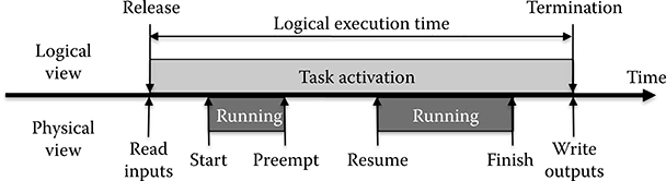
FIGURE 6.1 Logical execution time.
6.2.2.4 Modes
Modules that encapsulate a state machine have a dedicated start mode each and can switch between modes independently of others. A mode m specifies a mode period Pm (in microseconds) and a set of activities. As long as a module remains in mode m, the activities associated with m are repeated with period Pm. A mode activity either is a task invocation, an actuator update, or a mode switch. Mode activities may be guarded. A guard is a function that returns either true or false. A guarded mode activity is executed only if its guard evaluates to true.
When defining a mode activity within a mode, a frequency f for this activity is specified. This frequency divides the mode period Pm into slots of duration Pm/f each. These slots define the times during the mode period at which the guard of the activity is evaluated and the activity is executed. Actuator updates and mode switches are executed at the end of a slot. Task invocations result in the release of a task activation at the beginning and the termination of the particular activation at the end. Thus, the LET of an activation spans the entire slot, and, by default, the task invocation is executed in each slot.
For control systems, the fixed relationship between the rate of task invocations and the LET of each task activation poses problems as the delay between reading the sensors and updating the actuators consumes phase reserve in the control loop (e.g., Ref. [11]). Besides increasing the frequency of a task invocation and thus the sampling rate, which may be prohibitive in terms of CPU load, TDL offers two mechanisms for dealing with this situation: slot selection and task splitting.
Slot selection is the explicit selection of the slots in which a mode activity should be executed. For task invocations, slot selection maintains the basic pattern of freezing the input ports of a task at the release of each of the task activations and updating the output ports (and actuators) at termination. It allows a separation between the specification of the LET of a task activation and the repetition rate of the associated task. Slots that are not selected go unused.
Task splitting means to split the single task function into two functions, one called fast step and the other called slow step. TDL assumes that the fast step does not consume any time. At release time, first the input ports of the task are updated and then the fast step is executed. As a modification of the basic actuator update pattern, there is the possibility to update an actuator with a value calculated in the fast step immediately after it has finished execution. The slow step is executed afterwards, during the LET of the activation. At the termination time, the output ports of the task are updated and further actuator updates may be performed. In a control system application, for example, the actual controller may be moved into the fast step. Thus, the delay between reading the output of the plant and updating the actuator that delivers the input to the plant is minimized. A state estimator (e.g., [11]), representing a higher computational load, will then be moved into the slow step.
6.2.2.5 Asynchronous (= Event-Triggered) Activities
In addition to time-triggered (alias synchronous) activities, it is often necessary to execute event-triggered (alias asynchronous) activities as well [12]. TDL supports asynchronous task invocations and actuator updates. Such an asynchronous activity is triggered either by an update of an output port, by the occurrence of a hardware interrupt, or by the tick of a timer that may potentially introduce its own time base.
By integrating asynchronous activities into TDL, the TDL runtime system is able to provide the synchronization of the data flow between synchronous and asynchronous activities. It has been shown in Ref. [13] that a lock-free synchronization approach with a negligible impact on the timing of the time-triggered activities is possible with the semantics outlined below.
Events may be associated with a priority and are registered in a priority queue when they arrive. Processing the events is delayed and supposed to be performed sequentially by a single background thread that runs whenever there are no time-triggered activities to perform. Input ports are read as part of the asynchronous execution, not at the time of registering an event. Output ports are updated immediately after an asynchronous task invocation has finished. If an activity is triggered again before it has started to execute, it will not be executed a second time but remains registered once. In the case of a distributed system, the communication of asynchronous output values to remote nodes is supposed to rely on asynchronous network operations. Since any network operation introduces a delay, the transparent distribution property (see Section 6.2.1.3) does not hold in the case of asynchronous activities [14].
6.2.3 Example TDL Modules
The following example of two TDL modules exemplifies the textual syntax of TDL (Figure 6.2). As an alternative to the textual representation, the TDL toolchain also provides a syntax-driven editor that supports a visual and interactive modeling of TDL modules (see Figure 6.6 later in the chapter).
module Sender {
sensor int s1 uses getS1;
actuator int a1 uses setA1;
public task inc {
input int i;
output int o := 10;
uses incImpl(o);
}
start mode main [period=5ms] {
task
[freq=1] inc(s1);//LET = 5ms/1 = 5ms
actuator
[freq=1] a1 := inc.o;
mode
[freq=1] if exitMain(s1) then freeze;
}
mode freeze [period=1000ms] {}
}
module Receiver {
import Sender;
…
task clientTask {
input int i1;
…
}
start mode main [period=10ms] {
task
[freq=1] clientTask(Sender.inc.o); //LET = 10ms
…
}
…
}
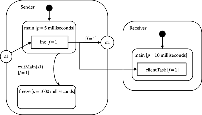
FIGURE 6.2 Sample TDL application.
Module Sender contains a sensor variable s1 and an actuator variable a1. The value of s1 is updated by executing the (platform-specific) function getS1 and the value of a1 is sent to the physical actuator by using the platform-specific function setA1. The declaration of task inc contains an input port i and an output port o with an initial value of 10. This task is invoked in the mode main, where it reads input from the sensor s1. In the same mode, actuator a1 is updated with the value of the task’s output port. The timing behavior of the mode activities is specified by means of individual frequencies within their common mode period. For example, with a frequency of 1, the activation of task inc is defined to have a LET of 5 milliseconds. The second module called Receiver imports the Sender module to connect the output of the task inc with the input of the task clientTask.
6.2.4 TDL Toolchain
TDL introduces appropriate abstractions to separate timing from functionality and platform-independent from platform-specific aspects. To obtain executable software, the textual TDL description must be compiled and combined with external functions that implement the required functionality. Figure 6.3 outlines the TDL tool-chain. It shows as a central component the TDL compiler that compiles a textual TDL program to platform-independent embedded code (so-called E-code). The TDL compiler also offers a plug-in-architecture for generating target platform-specific output. For example, on an automotive platform with OSEK as the operating system, the platform-specific output could include the so-called OIL files [15]. The E-code together with the platform-specific output and the functionality code corresponding to task function implementations is used by the TDL runtime system, the so-called E-machine [16], to execute TDL applications.
FIGURE 6.3 TDL toolchain.
6.2.4.1 E-Code
The TDL compiler generates E-code for each mode of a module. The E-code covers a single mode period and is repeated by means of a jump instruction to the beginning of the mode. For every logical time instant at which E-code must be executed, one E-code block is generated. An E-code block is a list of E-code instructions. It specifies for one logical time instant the actions that must be taken by the E-machine to comply with the timing specifications and LET semantics. The following generic sequence of actions comprises one E-code block for a logical time instant t:
Update the output ports of all tasks that are defined to be terminated at t.
Update all actuators that are defined to be updated at t.
Switch mode if a mode switch is defined at t.
Update the input ports of all tasks that are defined to be released at t.
Release all task activations that are defined to be released at t.
Sleep until the next logical time instant that must execute E-code.
Sensors are read whenever their value is required. However, at one particular logical time, a sensor is read at most once.
In the following, we illustrate these actions for the module Sender from the previously described example. At time 0, actions in the start mode are processed. Output ports are initialized and connected actuators are updated. Then, the sensor s1 is read and an activation for task inc is released. There are no further actions to be processed at time 0. At time 5, which is the end of the LET of the first activation of task inc, the task’s output port is updated. Following this, the actuator a1 is updated. Next, the mode switch condition in the guard function exitMain is evaluated. This causes sensor s1 to be read, and the value is provided as input to exitMain. If the guard evaluates to true, a mode switch to the empty mode freeze is performed, and no further actions are processed. Otherwise, the module remains in the mode, and the next activation for task inc is released. Figure 6.4 shows the periodic execution pattern of the task inc in mode main of module Sender and of the task clientTask of module Receiver.
In Section 6.2.4, we describe and compare the integration of TDL with the two simulation environments MATLAB and Simulink and Ptolemy. As these two environments are quite different, this requires two entirely different integration strategies. This applies to both modeling and simulation. Whereas Ptolemy is open source, targeted to support different models of computation, and highly adaptable even for fundamental elements, MATLAB and Simulink is proprietary and more restrictive in its adaptability.
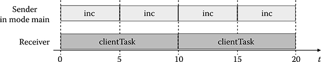
FIGURE 6.4 Periodic execution of the tasks inc and clientTask.
6.3 TDL Integration with MATLAB® and Simulink®
Simulink builds on MATLAB (both products by MathWorks) [6] and has become the de facto standard for the modeling and simulation of real-time systems in various domains such as automotive, avionics, and aerospace. First attempts to integrate TDL with MATLAB and Simulink started as early as the initial development of TDL in 2003 [17]. In Simulink, systems are modeled in a visual and interactive environment using (mostly time-based) block diagrams. Code generators may then automatically translate the block diagrams into software, for example, into C code.
According to the results described in Ref. [18], manually implementing LET semantics in Simulink is strongly discouraged. Even simple models of single-mode systems are cluttered with additional blocks to ensure that the timing behavior in the simulation conforms to LET semantics. It turned out that it is practically infeasible to model LET-based applications with multimodal behavior by hand, even when using the Simulink extension Stateflow® [6]. In the following, we describe an approach that is based on an explicit timing specification with TDL. For the simulation, the TDL specification is automatically translated into a Simulink model with an E-machine implementation at its core. In this sense, MATLAB and Simulink represents yet another execution platform for TDL modules.
6.3.1 Application Developer’s Perspective
We will start with a developer’s perspective of the TDL integration with MATLAB and Simulink that covers the modeling, the simulation, and finally the platform mapping and the code generation.
6.3.1.1 Extension of the TDL Toolchain for MATLAB® and Simulink®
Figure 6.5 outlines the TDL toolchain when used together with MathWorks tools. Real-Time Workshop® Embedded Coder™ [20] (RTW-EC in Figure 6.5) can be used to generate the C source code for the TDL task implementations. The so-called TDL:VisualCreator tool allows the visual and interactive modeling of TDL applications. For mapping TDL modules to specific platforms, that is, for organizing the various build steps, we provide the so-called TDL:VisualDistributor tool. It allows a developer to
Define a hardware topology. This can be a single node or a cluster consisting of potentially heterogeneous nodes that are connected, for example, through a time-triggered Ethernet.
Assign the individual TDL modules to their target nodes.
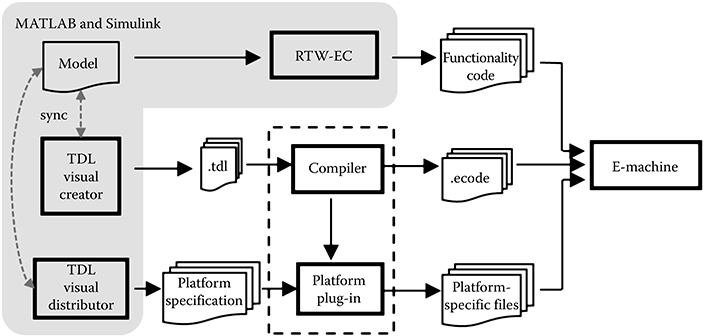
FIGURE 6.5 TDL toolchain in MATLAB® and Simulink®.
A built-in code and schedule generation framework generates platform-specific code, a communication schedule in the case of a distributed platform, makefiles, and any other output required for a particular platform [4].
6.3.1.2 Modeling
The modeling typically comprises two principal components: the controller and the plant. The plant is modeled as usual in MATLAB and Simulink. The controller is modeled with one or multiple TDL module block(s) (Figure 6.6) available in the TDL library.
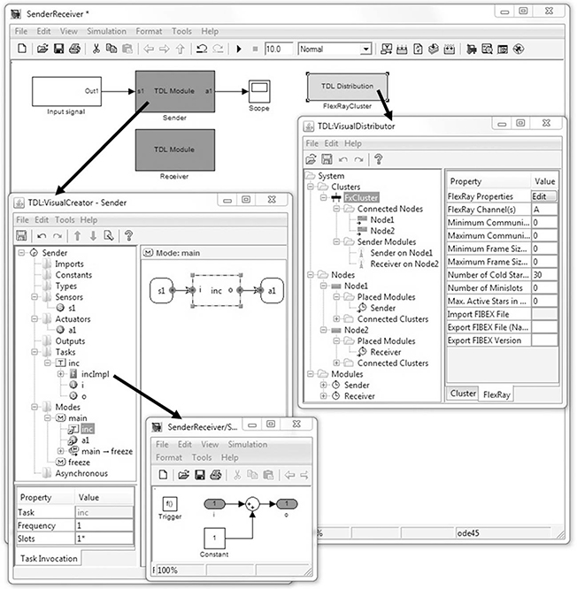
FIGURE 6.6 Modeling with the TDL toolchain in MATLAB® and Simulink®.
Each TDL module block represents one TDL module. Instead of using the textual representation of TDL, the module is edited using the TDL:VisualCreator tool that opens when double-clicking a TDL module block. The TDL module is two-way synchronized with Simulink. This means that a change in the TDL:VisualCreator, such as adding a sensor, is immediately reflected in the Simulink representation of the particular TDL module and vice versa. A sensor of the TDL module is represented as Inport, and an actuator is represented as Outport of the TDL module block. A task is represented as a (Function-Call) Subsystem that resides within the TDL module block. Within this subsystem, the functionality of the task may be modeled with appropriate library blocks (excluding those that comprise continuous-time behavior) with inherited sample time. Figure 6.6 shows the previously described TDL example within a MATLAB and Simulink model and the two tools TDL:VisualCreator and TDL:VisualDistributor. The TDL:VisualCreator tool lists the individual elements such as the sensor s1 and the task inc of module Sender in a tree representation. The activities of mode main, for example, are shown in the right-hand half of the frame. Their timing is specified through properties in the table below the tree representation.
6.3.1.3 Simulation
The overall system can be simulated once the application developer has finished the modeling phase, that is, timing behavior has been specified using the TDL:VisualCreator, whereas controller functionality and plant behavior have been modeled with Simulink blocks. From the developer’s point of view, there is no observable difference to starting a simulation if there were no TDL blocks present. This is achieved by an internal model translation (as sketched in the toolchain) to ensure that the simulation corresponds with the TDL specification. In fact, during the simulation, the compiled TDL program is executed within an E-machine encapsulated in a Simulink S-function. Details of how this is accomplished are described below.
As the TDL code and the schedule generators ensure that the timing behavior of TDL modules is equivalent when executed on a single node and when distributed among multiple nodes, the simulation can assume execution is on a single node and it is not necessary to account for any communication behavior.
6.3.1.4 Platform Mapping and Code Generation
To generate code for the application, the target platform must be specified. This is performed with the TDL:VisualDistributor tool that is integrated with Simulink as a TDL Distribution block (see the shaded box in the top-right corner of the Simulink model in Figure 6.6). The platform involves the specification of the (potentially heterogeneous) node platforms, their interconnections within the cluster, and the communication protocol. For this purpose, the developer may choose from a set of available node (such as a dSpace MicroAutoBox for prototyping) and cluster (such as FlexRay) plug-ins. After every TDL module of the Simulink model has been assigned to a node, the developer may start the generation of platform-specific code, a communication schedule in the case of distributed platforms, makefiles, and any other required output. If desired, the TDL:VisualDistributor tool can also trigger the RTW-EC to generate C code for all the tasks of the TDL modules.
6.3.2 Implementation Perspective
On an embedded hardware platform, the E-machine represents the core piece for a LET-based execution. E-machine implementations exist for several different platforms [21]. For the TDL integration with MATLAB and Simulink, we implemented an E-machine that is based on a Simulink S-function [18]. An S-function is a Simulink block that references a user-defined functionality implemented in a programming language such as C and compiled by the MATLAB EXecutable (MEX) compiler. In this way, the built-in Simulink blockset can be extended. S-functions are composed of callback methods that the Simulink engine executes at particular points during the simulation.
As the S-function implements the E-code interpreter, it must be invoked whenever the simulation time matches the logical time of a TDL activity, as defined in the E-code. According to the E-code instructions, the S-function triggers the execution of Simulink Function-Call Subsystems. Each task and each guard is represented as a Function-Call Subsystem that is provided by the developer. Additional Function-Call Subsystems are generated automatically as part of the model translation when the simulation is started. They implement the port assignment operations, for example, to update an actuator port with the value of a task output port.
Figure 6.7 exemplifies this E-machine approach for a simplified application. The placement of the individual blocks conforms to the data flow, which is basically from left to right along the arrows from a source to a sink. The source value is read by a sensor, which provides the value to a guard and a task. The actuator block uses the output port of a task to write to a sink. The E-machine triggers the individual blocks according to the E-code resulting in the indicated order (1–6). The input port of such a generated subsystem is directly connected to the output port, which corresponds to an assignment in the imperative programming paradigm as soon as the system is triggered. This ensures the correct LET behavior of a task activation, for example, when triggering its release and termination at the correct time instants. Both fixed and variable sample time approaches for the E-machine are possible [22]. The suggested value for a fixed sample time is the GCD (greatest common divisor) of all activity periods.
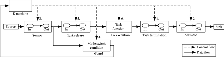
FIGURE 6.7 Basic principle of an E-machine as a Simulink® S-function and Function-Call Subsystems.
6.3.2.1 Resolving Data Dependencies
The S-function implementation of the E-machine for a simulation environment is analogous to E-machine implementations for hardware platforms. Compared to other simulation approaches, such a Simulink E-machine results in an efficient simulation model [18]. However, because of data dependency problems that can occur in simulation environments, the practical applicability of this basic mechanism turned out to be limited. We identified the following application scenarios that in general cannot be handled by this integration concept:
Cyclic import relationships between LET-based controllers (TDL modules)
Control loops involving plants without delay
Control loops with mixed LET-based and conventionally modeled controllers
These cases are discussed in detail in Ref. [22]. They are all related to cyclic data flow dependencies and the ability of the simulation environment to find a valid strategy for executing each individual block. Like many other simulation environments, Simulink does not support cycles without a delay except for special cases [23]. Delays are introduced by explicit delay blocks or by other blocks whose output is not directly controlled by the input (although possibly dependent on the block state). Those blocks are said to have indirect (or nondirect) feedthrough. When Function-Call Subsystems are involved, Simulink reports a data dependency violation, which is similar to an algebraic loop error [24], when attempting to simulate a model with a direct data dependency cycle. >From the control engineer’s point of view, this appears to be counterintuitive, since the LET of a task is always greater than zero and thus should introduce the required delay. The problem is that the simulation environment is not aware of this LET characteristic.
In Ref. [25], we propose an E-machine implementation that consists of two interacting S-functions. Without violating the TDL specification, that is, without changing the timing behavior of the simulation, this approach introduces additional delay blocks to resolve the cyclic dependencies. This two-step E-machine architecture is capable of simulating these three scenarios with cyclic data flow dependencies and also supports TDL applications with mixed time- and event-triggered (asynchronous) activities [22]. In the case of simulating event-triggered activities, the simulation of events and the corresponding reaction cannot be guaranteed to match the behavior on a specific target platform. This is because asynchronously activated tasks do not have a LET and also because the simulation is not aware of any scheduling strategy, distribution topology, or CPU speed of the target platform.
6.4 Tdl Integration With Ptolemy Ii
Ptolemy II is the software infrastructure of the Ptolemy project [7], which studies modeling, simulation, and design of concurrent, real-time, and embedded systems. It is an open source tool written in Java that allows modeling and simulation of systems adhering to various models of computation (MoC). Conceptually, a MoC represents a set of rules, which govern the execution and interaction of model components. The implementation of a MoC is called a domain in Ptolemy. Some examples of existing domains are Discrete Event (DE), Continuous Time (CT), Finite State Machines (FSM), and Synchronous Data Flow (SDF).
Ptolemy is extensible in that it allows the implementation of new MoCs. Most MoCs in Ptolemy support actor-oriented modeling and design, where models are built from actors that can be executed and that can communicate with other actors through ports. The nature of communication between actors is defined by the enclosing domain, which is itself represented by a special actor, called the domain director. Simulating a model means executing actors as defined by the top-level model director.
6.4.1 TDL Domain
TDL is implemented as an experimental domain in Ptolemy. The TDL domain consists of three specialized actors: TDLModule, TDLMode, and TDLTask. The TDLModule actor (with the associated TDLModuleDirector) restricts the basic modal model behavior according to the TDL semantics. In modal models, mode switches are made whenever a mode switch guard evaluates to true, whereas in TDL modules, mode switches are only allowed at predefined points in time. Similar restrictions apply to port updates. To ensure the LET of a task activation, input ports are only allowed to be read once, at the beginning of the LET, and output ports are only allowed to be written at the end of the LET and not when a task finished its computation. TDL requires a deterministic choice of one of all simultaneously enabled transitions, which is not provided by the FSM domain. We resolve this by employing a convention similar to the one supported by Stateflow [19], where the outgoing transitions of the active mode are tested based on the graphical layout, in clockwise order starting from the upper left corner of the graphical representation of the mode. TDL timing information such as the mode period is associated with TDL actors in the model.
TDL activities are conceptually regarded as DEs that are processed in increasing time stamp order. Thus, a TDL module can be seen as a restricted DE actor. This enables the usage of TDL modules inside every domain that is amenable to DE actors. A TDL task is implemented as an SDF actor, which executes in logically zero time. The top-level director is a DE director. The DE director uses a global event queue to schedule the execution of actors in the model. The TDL module places events in this queue for every time stamp where at least one TDL action is scheduled.
The module Sender from the example above modeled in Ptolemy is shown in Figure 6.8. The model shown in the top-left box of the figure contains a TDL Module and two actors to provide sensor values and display actuator values. The TDL Module contains two modes Main and Freeze (see Figure 6.8, the bottom-left box). Both modes have their period indicated by an associated parameter. The Main mode contains the task and the association of sensor and actuator values to input and output ports of the task. The frequency of the task invocation, which determines the LET, is defined as a parameter.
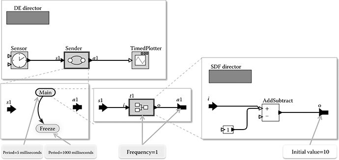
FIGURE 6.8 TDL module Sender in Ptolemy II.
Because of the iterative execution strategy of Ptolemy, problems with irresolvable cyclic dependencies as described for the Simulink integration do not arise. As the LET is always greater than zero, there is an actor without a direct dependency between inputs and outputs. Consequently, the DE director is able to resolve the loop and to process the TDL actions represented as events in the correct order and potentially interleaved with the plant.
6.5 Comparison between the Simulink® and the Ptolemy II Integration
In the Simulink integration, the developer models the functionality (task implementations and the plant) as usual with Simulink blocks. Timing, mode switching logic, and the overall application data flow are expressed in TDL with the TDL:VisualCreator tool. The TDL toolchain automatically creates a simulation model that contains data flow and timing information. On the other hand, the open and extensible architecture of Ptolemy facilitates the expression of all TDL semantics directly in the model. In Ptolemy, the timing specifications of TDL are expressed as properties of the respective actors (i.e., within the simulation model), whereas in Simulink, we abstract from both the simulation and the execution platform.
Both approaches extend the existing simulation framework with new blocks (actors) that ensure the TDL semantics during the simulation. In Simulink, the timing requirements are encoded in a static E-code representation and enforced by an E-machine, resulting in a low computational overhead. In Ptolemy, TDL actions, such as releasing a task activation or performing a mode switch, are generated dynamically and are represented as DEs. They are enqueued in the event queue of the DE director, which then schedules the appropriate TDL actions at their corresponding time instants. This independence of E-code may make experiments with future TDL extensions more straightforward, because testing new features with Simulink potentially requires changing the compiler, the E-code instruction set, and the E-machine.
6.6 Related Work
There is a Simulink integration of another LET-based language called HTL [26]. The HTL compiler is capable of compiling an HTL description into a Simulink model, which is then equipped with functionality for the control laws. The Simulink integration supports the hierarchical structure of HTL descriptions but restricts communication with the environment (plant model) to a single module, which limits the support for simulating distributed applications. Although HTL, similar to TDL, is based on an E-code variant, the HTL Simulink integration does not follow an E-machine approach but uses standard built-in MATLAB and Simulink blocks. This results in a simulation that does not exhibit the same behavior as the execution of the generated code, since the timing is distorted in several situations (e.g., by Unit-Delay blocks).
Simulink is closely related to synchronous languages. The simulation engine of Simulink executes subsystems implementing controller functionality in logical zero time. However, the semantics of Simulink are not defined formally [27], whereas synchronous languages are based on strict formal definitions and aim at formal verifiability. In several approaches, synchronous languages are combined with Simulink:
Argos, a synchronous language with a rigorously defined graphical notation, is prototypically embedded in Simulink as a less powerful but also less complicated alternative to Stateflow [28]. The implementation assumes that outputs calculated in response to an event are provided immediately. An extension [29] accounts for computational delays and corresponds to the implementation of the synchronous languages Argos and Esterel, where the response must be provided before a next event occurs. In both approaches, a synchronous program is embedded in Simulink.
The work by Caspi, Adrian, Maignan, Sofronis, and Tripakis [30] focuses on the conversion of a Simulink model into a synchronous program. Simulink systems consisting of a predefined subset of discrete-time blocks are translated automatically into Lustre, such that the original Simulink behavior is preserved. This enables the usage of tools for formal validation, simulation, synthesis, and so on. Another work [31] also includes Stateflow blocks. Caspi, Curic, Maignan, Sofronis, Tripakis, and Niebert [32] apply these results in the context of distributed systems. They present a layered end-to-end approach by translating Simulink models to the Lustre-based modeling environment SCADE in a first step. In a second step, the Lustre program is annotated to define timing assumptions and requirements and to specify the mapping to individual nodes. Finally, the application is mapped to a Time-Triggered Architecture (TTA) cluster [9].
The MathWorks product SimEvents® [6] extends Simulink with a mechanism for discrete-event simulation. This allows for simulating models that comprise continuous-time, discrete-time, and discrete-event components. Similar to the TDL integration with Ptolemy, an event-based scheduling can ensure the correct LET semantics of tasks in Simulink. However, based on the experience gained in the previous work, we doubt that a manual modeling of LET semantics scales to complex applications with multimodal behavior. A future research project may attempt to combine SimEvents with the TDL-based approach. Our Simulink integration could especially benefit from the event-based approach to simulate asynchronous activities of TDL. It is also conceivable that the E-machine is not sample-based but is itself triggered asynchronously by events.
TrueTime [33] is a Simulink toolbox for simulating networked control systems. It facilitates the cosimulation of control tasks, network transmissions, and continuous plant dynamics. TrueTime addresses the fact that traditional control design in MATLAB and Simulink often disregards temporal behavior and introduces a real-time kernel to be simulated in parallel with the plant. The kernel block is implemented as an S-function that simulates a flexible real-time kernel and provides support for A/D and D/A converters, network connections, and interrupt channels. It is event-driven and supports both periodic and aperiodic tasks. Different scheduling mechanisms, such as rate-monotonic or earliest-deadline-first, may be used. Control tasks are implemented in MATLAB functions, C, or Simulink blocks. For simulating distributed applications, network blocks support different network types. TrueTime allows a developer to experiment with various scheduling mechanisms and to investigate the true timing behavior of control applications in Simulink, taking into account latencies, execution times, jitter, and network effects. It requires execution times, distribution, and scheduling mechanism to be known in advance to approximate the behavior on the real execution platform. It is a platform-centered approach, whereas simulating TDL modules abstract from the platform and the network topology.
The TDL domain in Ptolemy II is related to the experimental Giotto domain in Ptolemy II [34]. The Giotto domain is designed based on basic Ptolemy II software components, whereas the TDL domain leverages the existing DE domain. The implementation of the TDL domain reflects the distinction between the fundamental concepts (LET, modes) and the manner in which these concepts are used (the operational semantics). The implementation is two-layered: the basic layer pertains to scheduling LET-based tasks grouped in modes, and the operational layer corresponds to a specific time-triggered programming model. The latter extends the basic layer by specifying additional operations as well as the order of data transfer and mode-change operations according to the programming model semantics. In principle, this forms the basis of domain controllers for any other time-triggered programming models (including Giotto) by extending the basic layer.
6.7 Conclusion
The LET allows the explicit specification of timing behavior independent of a specific platform, that is, LET abstracts from the physical execution time and thus from the execution platform and the communication topology. Thus, LET-based systems exhibit behavior equivalent or close to the platform without the necessity to specify platform details. Another significant advantage compared to the state-of-the-art is that the resulting embedded real-time systems generated from a LET-based language such as TDL are deterministic, composable, and portable. In this chapter, we presented the core concepts of TDL and its integration in two quite different modeling and simulation environments: MATLAB and Simulink and Ptolemy II. In both the cases, the integration concept and its implementation ensure that the simulation of time-triggered tasks exhibits the same behavior as the execution of the generated code on any potentially distributed hardware platform.
References
1. Edmondson, James, and Doug Schmidt. 2012. “Towards Accurate Simulation of Large-Scale Systems via Time Dilation.” In Real-Time Simulation Technologies: Principles, Methodologies, and Applications, edited by Katalin Popovici, Pieter J. Mosterman. Boca Raton, FL: CRC Press.
2. Stankovic, John A. 1988. “Misconceptions about Real-Time Computing: A Serious Problem for Next-Generation Systems.” Computer 21 (10): 10–9.
3. Henzinger, Tom, Ben Horowitz, and Christoph Kirsch. 2003. “Giotto: A Time-Triggered Language for Embedded Programming.” Proceedings of the IEEE 91: 84–99.
4. Chrona. 2011. http://www.chrona.com.
5. Zander, Justyna, Ina Schieferdecker, and Pieter J. Mosterman, eds. 2011. Model-Based Testing for Embedded Systems. Boca Raton, FL: CRC Press.
6. MathWorks. 2011. www.mathworks.com.
7. Eker, Johan, Jorn Janneck, Edward A. Lee, Jie Liu, Xiaojun Liu, Jozsef Ludvig, Stephen Neuendorffer, Sonia R. Sachs, and Yuhong Xiong. 2003. “Taming Heterogeneity: The Ptolemy Approach.” Proceedings of the IEEE, Special Issue on Modeling and Design of Embedded Software 91 (1): 127–44.
8. TDL language report, white papers, tool demo, and tool download. 2011. http://www.chrona.com/en/resources/white-papers.
9. Kopetz, Hermann. 1997. Real-Time Systems: Design Principles for Distributed Embedded Applications. Norwell, MA: Kluwer Academic Publishers.
10. Farcas, Emilia, Claudiu Farcas, Wolfgang Pree, and Josef Templ. 2005. “Transparent Distribution of Real-Time Components Based on Logical Execution Time.” SIGPLAN Not 40 (7): 31–9.
11. Franklin, Gene, Michael Workman, and David Powell. 1997. Digital Control of Dynamic Systems. 3rd ed. Boston, MA: Addison-Wesley Longman Publishing Co.
12. Scaife, Norman, and Paul Caspi. 2004. “Integrating Model-Based Design and Preemptive Scheduling in Mixed Time- and Event-Triggered Systems.” In Proceedings of the 16th Euromicro Conference on Real-Time Systems (ECRTS ’04), Catania, Italy, pp. 119–126, Washington, DC: IEEE Computer Society.
13. Templ, Josef, Johannes Pletzer, and Wolfgang Pree. 2009. “Lock-Free Synchronization of Data Flow between Time-Triggered and Event-Triggered Activities in a Dependable Real-Time System.” In Proceedings of the Second International Conference on Dependability, DEPEND, pp. 87–92. Washington, DC: IEEE Computer Society.
14. Templ, Josef, Johannes Pletzer, and Andreas Naderlinger. 2008. Extending TDL with Asynchronous Activities, Technical Report, University of Salzburg, http://www.softwareresearch.net/fileadmin/src/docs/publications/T022.pdf.
15. OSEK/VDX. 2004. System Generation, OIL: OSEK Implementation Language, Specification Version 2.5. www.osek-vdx.org.
16. Henzinger, Thomas A., and Christoph M. Kirsch. 2002. “The Embedded Machine: Predictable, Portable Real-Time Code.” ACM Trans. Program. Lang. Syst., 29(6):33–61, October 2007.
17. Stieglbauer, Gerald, and Wolfgang Pree. 2004. Visual and Interactive Development of Hard Real Time Code. Automotive Software Workshop (ASWSD), San Diego.
18. Stieglbauer, Gerald. 2007. Model-Based Development of Embedded Control Software with TDL and Simulink. PhD thesis, University of Salzburg.
19. MathWorks. 2010. Real-Time Workshop Embedded Coder 5, User’s Guide.
20. Farcas, Claudiu. 2006. Towards Portable Real-Time Software Components. PhD thesis, University of Salzburg.
21. Naderlinger, Andreas. 2009. Modeling of Real-Time Software Systems Based on Logical Execution Time. PhD thesis, University of Salzburg.
22. Denckla, Ben. 2006. “Many Cyclic Block Diagrams Do Not Need Parallel Semantics.” SIGPLAN Not 41 (8): 16–20.
23. Mosterman, Pieter J., and John E. Ciolfi. 2004. “Interleaved Execution to Resolve Cyclic Dependencies in Time-Based Block Diagrams.” In CDC ’04: Proceedings of the 43rd IEEE Conference on Decision and Control, pp. 4057–62.
24. Naderlinger, Andreas, Josef Templ, and Wolfgang Pree. 2009. “Simulating Real-Time Software Components Based on Logical Execution Time.” In SCSC ‘09: Proceedings of the Summer Computer Simulation Conference, pp. 148–155.
25. Iercan, Daniel, and Elza Circiu. 2008. “Modeling in Simulink Temporal Behavior of a Real-Time Control Application Specified in HTL.” Journal of Control Engineering and Applied Informatics (CEAI) 10 (4): 55–62.
26. Carloni, Luca, Maria D. Di Benedetto, Roberto Passerone, Alessandro Pinto, and Alberto Sangiovanni-Vincentelli. 2004. Modeling Techniques, Programming Languages and Design Toolsets for Hybrid Systems. Technical Report IST-2001-38314 WPHS, Columbus Project.
27. Bourke, Timothy, and Arcot Sowmya. 2005. Formal Models in Industry Standard Tools: An Argos Block within Simulink. International Journal of Software Engineering and Knowledge Engineering 15 (2): 389–96.
28. Bourke, Timothy, and Arcot Sowmya. 2006. “A Timing Model for Synchronous Language Implementations in Simulink.” In EMSOFT ’06: Proceedings of the 6th ACM & IEEE International Conference on Embedded Software, pp. 93–101. New York: ACM.
29. Caspi, Paul, Adrian Curic, Aude Maignan, Christos Sofronis, and Stavros Tripakis. 2003. “Translating Discrete-Time Simulink to Lustre.” In Rajeev Alur and Insup Lee, editors, EMSOFT, volume 2855 of Lecture Notes in Computer Science, pp. 84–99. Springer.
30. Scaife, Norman, Christos Sofronis, Paul Caspi, Stavros Tripakis, and Florence Maraninchi. 2004. “Defining and Translating a “Safe” Subset of Simulink/Stateflow into Lustre.” In EMSOFT ’04: Proceedings of the 4th ACM International Conference On Embedded Software, pp. 259–68. New York: ACM.
31. Caspi, Paul, Adrian Curic, Aude Maignan, Christos Sofronis, Stavros Tripakis, and Peter Niebert. 2003. “From Simulink to SCADE/Lustre to TTA: A Layered Approach for Distributed Embedded Applications.” SIGPLAN Not 38 (7): 153–62.
32. Cervin, Anton, and Karl-Erik Arzén. 2009. Model-Based Design for Embedded Systems, chapter TrueTime: Simulation Tool for Performance Analysis of Real-Time Embedded Systems. Boca Raton, FL: CRC Press.
33. Liu, Xiaojun, Stephen Neuendorfer, Yang Zhao, Haiyang Zheng, Christopher Brooks, and Edward A. Lee. eds. 2007. Heterogeneous Concurrent Modeling and Design in Java (Volume 3: Ptolemy II Domains). Berkeley, CA: EECS Department, University of California, UCB/EECS-2007–9.
34. Pree, Wolfgang, and Josef Templ. 2004. “Towards a Component Architecture for Hard Real Time Control Applications.” In Manfred Broy, Ingolf Krüger, and Michael Meisinger, editors, Automotive Software, Connected Services in Mobile Networks, volume 4147 of Lecture Notes in Computer Science, pp. 74–85. Berlin, Heidelberg: Springer.