
Narrowband Power Line Standards
CONTENTS
11.2 IEEE P1901.2 Working Group Draft
11.3 Recommendation ITU-T G.9902: G.hnem
11.3.1.5 Channel Estimation and Pilot Tones
11.3.2.1 Medium Access Control
11.3.2.3 Application Protocol Convergence
11.4 Recommendation ITU-T G.9903: G3-PLC
11.4.1.5 Channel Estimation and Pilot Tones
11.4.2.1 Medium Access Control Sublayer
11.4.2.2 IPv6 Adaptation Sublayer
11.4.2.3 The 2013 G.9903 Revision and LOADng
11.5 Recommendation ITU-T G.9904: PRIME
11.5.1.5 Channel Estimation and Pilot Tones
11.5.2.1 Medium Access Control
11.6.1 IEEE P1901.2 Preamble-Based Coexistence
11.7 A Qualitative Comparison of NB-PLC Technologies
11.7.1.1 NB-PLC Channel Assumptions
11.7.1.2 Coherent versus Differential Modulation
11.7.2 ‘Route-Over’ or ‘Mesh-Under’?
In this chapter, we will give an overview of the latest standardisation efforts in the Institute of Electrical and Electronics Engineers (IEEE) and the Telecommunication Standardization Sector of the International Telecommunication Union (ITU-T) on narrowband power line communication (NB-PLC). The list of acronyms used throughout this chapter can be found in Table 11.1.
One of the first low data rate (LDR) NB-PLC standards ratified is the American National Standards Institute (ANSI)/Electronic Industries Alliance (EIA) 709.1 standard, also known as LonWorks. Issued by ANSI in 1999, it became an international standard in 2008 (ISO/IEC 14908) [1]. This seven-layer Open Systems Interconnection (OSI) protocol provides a set of services that allow the application program in a device to send and receive messages to/from other devices over twisted pair or PLC. Achievable data rates are in the order of few kbps. The most widespread NB-PLC technologies deployed today are based on frequency shift keying (FSK) or spread-FSK as specified in the IEC 61334-5-2 [2] and IEC 61334-5-1 [3] standards, respectively. The availability of standards for these technologies goes from recommendations that specify the stack of communications protocols from the physical up to the application layer (IEC 62056-53 for COSEM) thus facilitating the development of interoperable solutions.
The increasing desire for higher data rates and the growing attention that smart metering projects are getting in various national efforts directed at modernising the aging power grid has led to a renewed interest in high data rate (HDR) NB-PLC solutions operating in the Comité Européen de Normalisation Électrotechnique (CENELEC)/Federal Communications Commission (FCC)/Association of Radio Industries and Businesses (ARIB) bands which are able to provide higher data rates than LDR NB-PLC [4]. For example, the Powerline Related Intelligent Metering Evolution (PRIME) initiative has gained industry support in Europe and has specified an HDR NB-PLC solution based on orthogonal frequency division multiplexing (OFDM) and operating in the CENELEC-A band [5]. A similar initiative, G3-PLC, was initiated in 2008 driven by Maxim Integrated Products, Sagemcom and ERDF who developed the G3-PLC specifications and brought them to the ITU-T. The G3-PLC Alliance was then formed few years later in 2011 [6]. G3-PLC is an OFDM-based HDR NB-PLC technology that can operate in the CENELEC and FCC bands, with many features aimed at improving reliability of communications, for example, adaptive tone mapping, Advanced Encryption Standard (AES)-128, concatenated coding, robust modes, and priority-based medium access. Both G3-PLC and PRIME were designed to be open public specifications. Several papers about PRIME and G3-PLC performance have appeared in the past few years [7,8,9,10,11,12].
List of Acronyms Used in This Chapter
Acronym |
Meaning |
Acronym |
Meaning |
6LoWPAN |
IPv6 over Low-power Wireless |
IoAC |
Interleave over AC cycle |
Personal Area Networks |
IoF |
Interleave over fragment |
|
AC |
Alternate current |
ISI |
Inter-Symbol Interference |
ACK |
Acknowledgement frame |
ISO |
International Organization for |
AES |
Advanced Encryption Standard |
ITU-T |
International Telecommunication Union – Telecommunication Standardization Sector |
AKM |
Authentication and Key Union – Management |
||
AMI |
Advanced Metering |
LDR |
Low data rate |
Infrastructure |
LF |
Low frequency |
|
ANSI |
American National Standards |
LLC |
Logical link control |
Institute |
LOAD/ |
Lightweight On-demand Ad hoc |
|
AODV |
Ad hoc On-Demand Distance- |
LOADng |
Distance-vector Routing |
Vector Routing |
Protocol – Next Generation |
||
ARIB |
Association of Radio Industries |
LPTV |
Linearly and periodically time |
and Businesses |
varying |
||
AWGN |
Additive white Gaussian |
LV |
Low voltage |
noise |
MAC |
Medium access control |
|
BPSK |
Binary phase shift keying |
MP2P |
Multi-point to point |
CCM |
Counter Cipher Mode |
MV |
Medium voltage |
CENELEC |
Comité Européen de |
NACK |
Negative acknowledgement |
Normalisation |
NB-PLC |
Narrowband PLC |
|
Électrotechnique |
NIST |
US National Institute of Standards |
|
CES |
Channel estimation symbol |
and Technology |
|
CFP |
Contention-free period |
NPCW |
Normal-priority contention |
CFS |
Contention-free slot |
window |
|
CP |
Contention period |
OFDM |
Orthogonal frequency division |
CPCS |
Common part convergence |
multiplexing |
|
sublayer |
OSI |
Open Systems Interconnection |
|
CRC |
Cyclic redundancy check |
P2MP |
Point to multi-point |
CSMA/CA |
Carrier sense multiple access/ |
P2P |
Point to Point |
collision avoidance |
PAN |
Personal area network |
|
CW |
Contention window |
PAP |
Priority action plan |
DLL |
Data link layer |
PEV |
Plug-in electric vehicle |
DM |
Domain master |
PFH |
PHY frame header |
DPSK |
Differential phase shift keying |
PHY |
Physical layer |
EAP-PSK |
Extensible authentication |
PLC |
Power line communications |
protocol–pre-shared key |
PRIME |
Powerline Related Intelligent |
|
EIA |
Electronic industries alliance |
Metering Evolution |
|
EMC |
Electromagnetic compatibility |
PSD |
Power spectral density |
ERM |
Extremely robust mode |
PSK |
Phase shift keying |
EUI |
Extended unique identifier |
QAM |
Quadrature amplitude modulation |
FCC |
Federal Communications Commission |
RCM |
Robust communication mode |
FCH |
Frame control header |
RERR |
Route Error |
FEC |
Forward error correction |
RPL |
Routing protocol for low-power and |
FSK |
Frequency shift keying |
Lossy networks |
|
HDR |
High data rate |
RREP |
Route Reply |
HNEM |
Home network energy |
RREQ |
Route Request |
management |
RS |
Reed-Solomon |
|
HPCW |
High-priority contention |
SAE |
Society of Automotive Engineers |
window |
SCP |
Shared contention period |
|
IEC |
International Electrotechnical |
SDO |
Standards Developing Organization |
Commission |
SGIP |
Smart Grid interoperability panel |
|
IEEE |
Institute of Electrical and Electronics Engineers |
SNR |
Signal-to-noise ratio |
IFS |
Interframe spacing |
SSCS |
Service-specific convergence sublayer |
Recognising the importance of standardising a next-generation NB-PLC technology, the IEEE Standards Association and the ITU-T started in 2010 the standardisation of next-generation OFDM-based NB-PLC technologies launching the IEEE P1901.2 [13] and ITU-T G.hnem (Home Networking Energy Management) projects, respectively. An effort was made to bring to official standardisation both PRIME and G3-PLC technologies and this was successfully accomplished in the ITU-T Study Group 15 Question 15 (Q15/15) [14]. As a consequence, the original G.hnem project was widened to include also G3-PLC and PRIME. The technical approach initially followed by G3-PLC was later adopted also in IEEE P1901.2 and ITU-T Q15/15, which have both inherited many of the technical features of G3-PLC.
The formation of the IEEE P1901.2 work group started in 2010 with PLC discussions among several companies attending automotive standards meetings. The discussions centred on how to standardise a sub-500 kHz power line communication solution that would meet the automotive specifications in the upcoming SAE J2931/3 [15] and the issued ISO/IEC 15118-3 [16]. At that time, there was no standardisation effort for PLC solutions above the CENELEC band and in the low-frequency (FCC and lower) range. IEEE P1901.2 came to life in fall 2009 with the IEEE Communications Society agreeing to serve as sponsor and the IEEE P1901.2 started its work in 2010. The IEEE P1901.2 Draft is still under study; it passed sponsor ballot and it should be ratified and published in 2014.
The first standards on next-generation OFDM-based NB-PLC to be approved were ITU-T Recommendations G.9955 [17] and G.9956 [18]. These two recommendations contain the physical layer (PHY) and data link layer (DLL) specifications, respectively, of three NB-PLC technologies: G.hnem, G3-PLC and PRIME:
1. G.hnem: A new NB-PLC technology developed by ITU-T members based on G3-PLC and PRIME. The PHY/medium access control (MAC) are specified in the main body of the G.9955/G.9956 Recommendations, and the solution operates over CENELEC-A–D bands and the US FCC band.
2. G3-PLC: An established and field-proven NB-PLC technology contributed by ITU-T members of the G3-PLC Alliance. The PHY is specified in Annex A (CENELEC-A band) and Annex D (FCC band) of G.9955; the DLL is specified in Normative Annex A of G.9956. The G3-PLC Annexes are normative and stand alone, that is, they can be implemented independently from the main body and the other annexes.
3. PRIME: An established and field-proven NB-PLC technology contributed by ITU-T members of the PRIME Alliance. The PHY/MAC are specified in Annex B and the solution operates over CENELEC-A band. The PRIME Annexes are normative and stand alone, that is, they can be implemented independently from the main body and the other annexes.
Basically, Recommendations ITU-T G.9955 and G.9956 define a family of three standalone international next-generation NB-PLC standards. These technologies are not interoperable with each other. To reduce confusion in the industry and allow better visibility to the each of the NB-PLC technologies, the three NB-PLC technologies mentioned above and specified in G.9955/G.9956 have been repackaged into three separate recommendations plus a fourth one containing the material with regulatory implication. Recommendations ITU-T G.9955/G.9956 were thus split into the following four separate ITU-T Recommendations which have received final approval in late 2012 and now supersede G.9955/G.9956:
1. G.9901 [19] ‘Narrowband OFDM Power Line Communication Transceivers–Power Spectral Density (PSD) Specification’. This recommendation contains all the material in G.9955 with regulatory relevance and implications, such as OFDM control parameters that determine spectral content, PSD mask requirements and the set of tools to support reduction of the transmit PSD.
2. G.9902 (G.hnem) [20] ‘Narrowband OFDM Power Line Communication Transceivers for ITU-T G.hnem Networks’. This recommendation contains the PHY and the DLL specifications for G.hnem NB-PLC transceivers. It uses the material in G.9955 and G.9956 as is, specifically using material in its main body and the Annexes that pertain to the main body. This recommendation normatively references G.9901.
3. G.9903 (G3-PLC) [21] ‘Narrowband OFDM Power Line Communication Transceivers for G3-PLC Networks’. This recommendation contains PHY and the DLL specifications for G3-PLC NB-PLC transceivers. It uses the material in G.9955 and G.9956 as is, specifically using material in Annexes A and D of G.9955 and Annex A of G.9956. This recommendation normatively references G.9901.
4. G.9904 (PRIME) [22] ‘Narrowband OFDM Power Line Communication Transceivers for PRIME Networks’. This recommendation contains the PHY and the DLL specifications for PRIME NB-PLC transceivers. It uses the material in G.9955, G.9956 and G.9956 Amdl as is, specifically using material in Annex B of G.9955, Annex B of G.9956 and G.9956 Amdl. This recommendation normatively references G.9901.
G3-PLC has evolved since its initial version and this evolution has been included in the Recommendation ITU-T G.9903 (2012) and its 2013 Revision. For example, G3-PLC as defined now in G.9903 has a coherent option in addition to its original mandatory differential modulation, higher-order modulations, and additional bandplans were added (CENELEC-B and ARIB).
11.2 IEEE P1901.2 Working Group Draft
The scope of the IEEE P1901.2 effort as outlined in its Project Authorisation Request (PAR) is the following [13]:
This standard specifies communications for low-frequency (less than 500 kHz) narrowband powerline devices via alternating current and direct current electric powerlines. This standard supports indoor and outdoor communications over a low-voltage line (line between transformer and meter, less than 1000 V), through a transformer low-voltage to medium-voltage (1000 V up to 72 kV), and through transformer medium-voltage to low-voltage powerlines in both urban and in long-distance (multikilometer) rural communications. The standard uses transmission frequencies less than 500 kHz. Data rates will be scalable to 500 kbps depending on the application requirements. This standard addresses grid-to-utility meter, electric vehicle-to-charging station, and within home area networking communications scenarios. Lighting and solar-panel powerline communications are also potential uses of this communications standard. This standard focuses on the balanced and efficient use of the powerline communications channel by all classes of low-frequency narrowband (LF NB) devices, defining detailed mechanisms for coexistence between different LF NB standards developing organizations (SDO) technologies, assuring that desired bandwidth may be delivered. It also ensures coexistence with broadband powerline (BPL) devices by minimizing out-of-band emissions in frequencies greater than 500 kHz. The standard addresses the necessary security requirements that assure communication privacy and allow use for security sensitive services. This standard defines the physical layer and the medium access sublayer of the data link layer, as defined by the International Organization for Standardization (ISO) Open Systems Interconnection (OSI) Basic Reference Model.
The IEEE P1901.2 Working Group is constituted by several subgroups to address solutions for various key areas. These areas included harmonisation technologies operating in low-frequency band; robustness for through-transformer communication; defining limits and testing for electromagnetic compatibility (EMC); defining complete coexistence mechanism with existing SDO technologies; and prioritising IP addressing. The EMC subgroup was formed to define EMC limits in areas where regulations are missing as for the FCC band, whereas limits exist for the CENELEC and ARIB bands. The EMC subgroup was additionally tasked to develop test criteria to meet these limits. A NB-PLC coexistence subgroup was also formed to address challenges to manage a simple and fair mechanism that could be globally applicable. To address global regulations, three main bands were defined: the CENELEC band (Europe, CENELEC bands A–D) which has an upper limit of 148.5 kHz, the ARIB band (JP) which has an upper limit of 450 kHz, and the FCC band (multiple countries) which has an upper limit of ∼490 kHz. Although these bands have definitive upper limits, it is customary to define subbands within these limits to maximise system parameters for optimal performance in varying conditions and to maximise shared bandwidth. An example of this would be an FCC subband which has a start frequency above the CENELEC bands at 154.7 kHz and a stop frequency at 488.3 kHz. Because of the inherently low EMC emissions (and, consequently, limited emissions), properly defined NB-PLC solutions can transmit in frequency bands with a relatively small guard band without disturbance-related issues.
Each subband is defined with a start and stop frequency and with a specific number of subcarriers (tones) per band. Once the number of carriers is defined, a table is generated that indicates the phase vector definition per carrier. With the known number of carriers per symbol, along with the number of symbols per PHY frame and the number of parity bits added by forward error correction (FEC) blocks, the PHY data rate can then be calculated. The number of symbols in each PHY frame is selected based on two parameters: the required data rate and the acceptable robustness.
As mentioned earlier, the IEEE P1901.2 is still under study and is not available publicly so only limited information is publicly available (see [23]). Since the P1901.2 Draft is still under study, the technical information reported here may not be correct and is also subject to change.
The PHY layer of the IEEE P1901.2 follows closely the PHY layers of G3-PLC. There are some differences that are related to the number of Reed–Solomon (RS) code words per frame, the frame control header (FCH), the interleaver, and the FCC tone spacing for the FCC bandplan. As work on IEEE P1901.2 is still ongoing, it is not possible at this time to state whether IEEE P1901.2 is interoperable or not with G.9903 (G3-PLC).
The MAC layer is an interface between the logical link control (LLC) and the PHY. The MAC layer regulates access to the medium using carrier sense multiple access with collision avoidance (CSMA/CA). It provides feedback to upper layers via the use of positive (ACK) and negative (NACK) acknowledgement frames, and also performs packet fragmentation and reassembly. Packet encryption/decryption is carried out by MAC as well. The primary areas developed in the MAC include the MAC sublayer service specification, MAC frame formats, MAC command frames, MAC constants, attributes such as interframe spacing (IFS), MAC functional description and MAC security-suite specifications.
The IEEE P1901.2 Draft focuses on OSI Layer 1(L1) and parts of OSI Layer 2 (L2) and does not normatively specify any L2 or Layer 3 (L3) routing mechanism. IEEE P1901.2 is agnostic to routing mechanism. In particular, a candidate for L2 routing is the Lightweight On-demand Ad hoc Distance-vector Routing Protocol – Next Generation (LOADng) [24]; for the L3 routing, a candidate is the Routing Protocol for Low-Power and Lossy Networks (RPL) [25]. LOADng and RPL are further discussed in Sections 11.4.2.2, 11.4.2.3 and 11.7.2.
A unique feature of IEEE P1901.2 that is not present in the ITU-T Recommendations is that it provides an optional adaptive multi-tone mask for the preamble and header. This allows for PHY/MAC protocols that facilitate additional reliable communication for low-voltage (LV)/medium-voltage (MV) crossing in the US grids [23].
11.3 Recommendation ITU-T G.9902: G.hnem
G.9902 targets all main Smart Grid applications: Advanced Metering Infrastructure (AMI) for residential and business sites, in-home energy management, including demand-response (DR) programs and smart appliances, home automation and plug-in electric vehicle (PEV) charging. The default G.9902 network layer protocol is IPv6, while others can also be supported using an appropriate convergence sublayer.
A G.9902 network consists of one or more logical domains, and a domain is constituted by all nodes registered in that domain (see Figure 11.1). Each node is identified by its domain ID and node ID. One node in the domain is assigned as a domain master (DM). The DM controls operation of all other nodes and performs admission, resignation and other domain-wide management operations. Domains of the same network are connected by interdomain bridges (IDB), allowing nodes in different domains to communicate. Any domain may also be bridged to a non-G.9902 (alien) domain.
The PHY can be programmed to operate in different bandplans over CENELEC, FCC and ARIB bands, over different types of power line wiring, such as MV, LV, in-home wiring and alternate current (AC) and pilot wires of PEV cables. Both synchronous beacons (sent periodically) and asynchronous beacons (sent at the discretion of the DM) are defined. If a node operating as a DM fails, the DM function is automatically passed to another node of the domain.
The NB-PLC technology specified in G.9902 is based on G3-PLC and PRIME, but is non-interoperable with the other technologies specified in IEEE and ITU-T. There are a few published papers on G.hnem (see [26,27]).
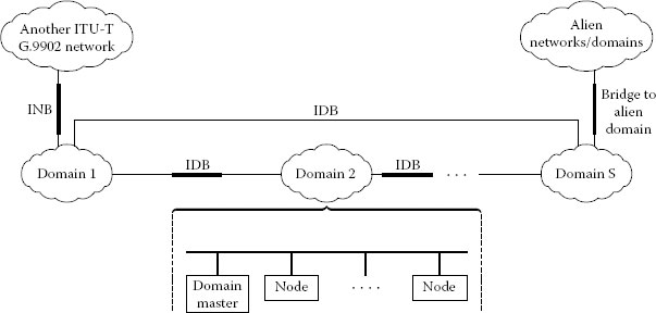
FIGURE 11.1
Generic network architecture. (From Narrowband orthogonal frequency division multiplexing power line communication transceivers for ITU-T G.hnem networks, ITU-T Rec. G.9902, October 2012. [Online] Available: http://www.itu.int/rec/T-REC-G.9902 (Fig. 5-1). With permission.)
G.9902 defines several bandplans. Support of at least one bandplan is mandatory. The CENELEC band (3–148.5 kHz) is divided into three bandplans: CENELEC-A (35.9375–90.625 kHz), CENELEC-B (98.4375–120.3125 kHz) and CENELEC-CD (125–143.75 kHz). Three bandplans are currently defined over the FCC band (9–490 kHz). Those are FCC (34.375–478.125 kHz), FCC-1 (34.375–137.5 kHz) and FCC-2 (150–478.125 kHz). The ARIB bandplan uses the 154.7–403.1 kHz range.
G.9902 uses windowed OFDM with the following set of programmable parameters:
• Number of carriers
• CENELEC: 128, of which 36, 15 and 13 carriers are active in the CENELEC-A, CENELEC-B and CENELEC-CD bandplans, respectively.
• FCC bandplan: 256, of which 143, 34 and 106 carriers are active in the FCC, FCC-1 and FCC-2 bandplans, respectively.
• Carrier spacing
• CENELEC bandplans: 1.5625 kHz
• FCC bandplan: 3.125 kHz
• Carrier modulation: Quadrature amplitude modulation (QAM) with 1, 2, 3 or 4 bits per carrier
• Guard interval: 0 for the frame header and*
• CENELEC bandplans: 60 and 120 ps for the payload
• FCC bandplans: 30 and 60 ps for the payload
• Size of transmitter windowing (PSD shaping)
• CENELEC bandplans: 8 samples
• FCC bandplan: 16 samples
The FEC encoder consists of an inner convolutional encoder with rate 1/2 and constraint length L = 7 and an outer RS encoder. A (2,1,6) mother convolutional code with rate 1/2 is used with the octal encoding matrix G = [171;133]; an additional rate of 2/3 is obtained by puncturing. The RS encoder uses input blocks up to 239 bytes and can be shortened to a 25-byte input block. The concatenated scheme is mandatory for payload data, while the RS encoder is bypassed for the PHY frame header (PFH). The interleaver is designed to combat both frequency domain and time domain erasures, including repetitive erasures with a period of 1/2 AC cycle and duration up to 1/4 AC cycle. For the payload, the interleaver first splits the payload into multiple fragments and then each fragment may be repeated for 2, 4, 6 or 12 times to increase robustness. Two modes of interleaving are defined:
1. Interleave over fragment (IoF)
2. Interleave over AC cycle (IoAC)
If the IoF mode is set, each fragment is interleaved separately. If the IoAC mode is set, each repeated fragment is further padded by additional repetitions up to the closest multiple of half AC cycle. The IoAC mode is used to handle channels with severe periodic erasures.
G.9902 allows the transmission of multiple RS code words per PHY frame. More in detail, G.9902 allows transmitting at most 64 segments in an LLC frame or having at most a 250 ms time on wire. This allows the transmission of up to 300 OFDM symbols in a single PHY frame.
In order to maximise throughput under varying channel conditions, G.9902 employs tone mapping. Tone mapping allows loading a specified number of bits on carriers based on the signal-to-noise ratio (SNR) per carrier. The frame header always uses QPSK on all carriers of the used bandplan, and the tone mapping used for the payload is indicated in the frame header. Only flat bit loading of 1, 2 and 4 bits/carrier is specified in G.9902, that is, all carriers are loaded with the same constellation.
11.3.1.5 Channel Estimation and Pilot Tones
Since G.9902 requires a coherent receiver, it is necessary to provide accurate synchronisation and channel estimation. This is accomplished by the use of a combination of channel estimation symbols (CES) and pilot carriers added at pre-defined locations in both the header and the payload. The CES are transmitted inside or right after the PFH; the modulation parameters of the CES, including transmitter windowing, are the same as for the preamble symbols. The position of pilot tones in each OFDM symbol is shifted by three carriers from the previous symbol to reduce interpolation errors. Pilot tones are also essential to improve reception in time-varying channels like the PLC channel.
For challenging links where node connectivity is compromised, G.9902 specifies a robust communication mode (RCM). Payload transmission in RCM uses a uniform loading of 1 bit per carrier (binary phase shift keying [BPSK]), with the possibility of repetition encoding with 2, 4, 6 or 12 repetitions. Repetitions are applied before interleaving. Protection of the PFH is critical since its loss implies the loss of the whole frame; thus, the PFH uses the rate 1/2 convolutional encoder plus 12 repetitions and an additional 12 bit cyclic redundancy check (CRC). An extremely robust mode (ERM) is specified optional in Annex A of G.9902. In ERM, repetitions can be set to 32, 64 or 128.
11.3.2.1 Medium Access Control
An ITU-T G.9902 node of a standard profile supports prioritised contention-based medium access with four priorities; nodes of low complexity profile support two priorities.
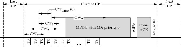
FIGURE 11.2
Example of contention period. (From Narrowband orthogonal frequency division multiplexing power line communication transceivers for ITU-T G.hnem networks, ITU-T Rec. G.9902, October 2012. [Online] Available: http://www.itu.int/rec/T-REC-G.9902 (Fig. 9-10). With permission.)
A contention-based prioritised CSMA/CA is specified. The three lower priorities are intended for user data frames, and the fourth priority is for frames carrying emergency signalling. All management frames are granted the third priority, to make network management more dynamic.
The prioritised contention-based medium access is defined in terms of contention periods (CP) (see Figure 11.2). The contention process starts at the beginning of the CP. The CP ends TIFG_MIN after the node that won the contention completes the transmission of the frame sequence, which includes the transmitted frame and the ACK frame (if required). A new CP starts immediately after the end of the previous CP. Each CSMA/CA CP starts with priority resolution. The CP will consist of four priority resolution periods that may also overlap. Each such period is associated with a contention window (CW) with adjustable size and position. CWs of different priorities may overlap. Each node picks randomly the transmission slot in the corresponding CW and then monitors the medium using physical carrier sensing via preamble detection. If the medium becomes busy prior to the chosen transmission slot, the node refrains from transmitting. Synchronised medium access is optional. If enabled, the DM coordinates nodes by periodically sending (synchronous) beacons.
Long packets are segmented so that the size of a segment fits actual channel conditions. For higher efficiency, a G.9902 frame may carry multiple segments, each encapsulated into a link protocol data unit and protected by its own CRC. Transmission of frames containing multiple segments is supported by a selective acknowledgement scheme. The receiver checks the CRC of each segment and acknowledges all corrupted segments, which are then retransmitted.
Similarly to IEEE P1901.2, G.9902 is agnostic to routing mechanisms. G.9902 allows performing mesh networking by using either L2 routing (by relaying the LLC frames) or L3 routing (by relaying the protocol data units above the A interface). Prior to initialisation, each domain will be set into a particular routing mode that either allows intradomain L2 routing (L2 relaying mode) or that disallows it (no L2 relaying is allowed for any node of the domain). If L2 routing is set for the domain, the DM assigns one or more nodes as relays.
11.3.2.3 Application Protocol Convergence
Although IPv6 is the default protocol for G.9902, it is also possible to support other networking protocols. Each protocol is supported by the corresponding application protocol convergence (APC) function. The type of APC used by the transmitter is indicated in the packet header.
Security is provided by encryption and authentication of the relevant data and management frames communicated between the nodes of the domain. Encryption and authentication of data and relevant management messages use the Counter with Cipher Block Chaining-Message Authentication Code (CCM) algorithm based on 128-bit AES-128. Node authentication, generation and distribution of encryption keys between nodes, encryption key updates and node authentication updates are provided by a set of Authentication and Key Management (AKM) procedures. The AKM procedure can establish both group keys (i. e. a unique set of keys for a particular group of nodes) and pairwise keys (i. e. a unique set of keys per every pair of communicating nodes).
11.4 Recommendation ITU-T G.9903: G3-PLC
The G3-PLC technology was originally conceived by Maxim Integrated Products, Sagemcom and ERDF, who brought the G3-PLC specs into the ITU-T where they were enhanced and additional functionalities were added. In parallel, companies from different areas (utilities, system integrators, meter manufacturers and silicon vendors) founded G3-PLC Alliance in 2011 with the objective of refining and enhancing the specifications, set up certification, and promote the technology. Several published papers on G3-PLC PHY performance and field trials are available (see [8,11,12] and references therein).
A G.9903 network consists of one or more domains (called a personal area network or PAN), and a domain is constituted by all nodes registered in that domain. Each node is identified by its PAN ID and short address (16 bit ID). One node in the domain is assigned as a DM (or PAN-coordinator). The coordinator controls operation of all other nodes and performs admission, resignation and other domain-wide management operations, in addition to connectivity to other domains or WAN.
The specification details given in the next sections pertain to the approved G.9903 Recommendation [21] and its Revision which was approved in May 2013. The following enhancements were made in the 2013 Revision of G.9903:
• Support for a new bandplan in CENELEC-B
• A Regional Annex for JP, with an ARIB bandplan (Annex K).
• The support for an optional coherent mode for use in CENELEC bandplans
• The update of RFC4944 by RFC6282 for header compression
• A new routing algorithm (LOADng) [24] that replaces the one used previously (LOAD) [28]
• A clause on coexistence with other NB-PLC technologies that also specifies when it is mandatory or optional
G.9903 specifies a CENELEC-A bandplan, three FCC bandplans, and an ARIB bandplan. When operating in the CENELEC-A bandplan, G.9903 uses the frequencies in the 35.938–90.625 kHz range with carrier spacing of 1.5625 kHz. The three FCC bandplans are FCC-1 (154.6875–487.5 kHz), FCC-1. a (154.687–262.5 kHz) and FCC-1.b (304.687–487.5 kHz). The ARIB bandplan uses the 154.7–403.1 kHz range. Tone masking allows the network manager to limit the bandwidth of the active band or to divide the band into smaller sub-bands to handle several domains. An Amendment currently under development is revising the FCC bandplans.
ITU-T G.9903 uses windowed OFDM with the following set of programmable parameters:
• Number of carriers
• CENELEC-A bandplan: 128, of which 36 are active
• FCC bandplan: 128, of which 72, 24 and 40 carriers are active in the FCC-1, FCC-1.a and FCC-1.b bandplans, respectively
• Carrier spacing
• CENELEC bandplans: 1.5625 kHz
• FCC bandplan: 4.6875 kHz
• Carrier modulation
• Mandatory differential phase shift keying (DPSK) with 1, 2 or 3 bits per carrier. This is the classical ‘time’ differential modulation where the information is encoded in the phase difference between two consecutive symbols. This is different from G.9904 where frequency domain differential modulation is employed.
• The optional coherent mode specifies phase shift keying (PSK) with 1, 2 and 3 bits per carrier and QAM modulation with 4 bits per carrier (16 QAM).
• Guard interval: 0 for the frame header
• CENELEC bandplans: 55 μs for the payload
• FCC bandplan: 18.3 μs for the payload
• Size of transmitter windowing (PSD shaping): 8 samples
ITU-T G.9903 uses an inner convolutional encoder with rate 1/2 and constraint length L = 7 and an outer RS encoder. The inner convolutional code is the same one used in G.9902. An RS (255, 239) is specified where the number of correctable symbol errors is 8. The concatenated scheme is mandatory for payload data, while the RS encoder is bypassed for the FCH.
ITU-T G.9903 specifies a channel interleaver designed to provide protection against two sources of errors:
1. A burst error that corrupts a few consecutive OFDM symbols
2. A frequency deep fade that corrupts a few adjacent tones for a large number of OFDM symbols
To fight both sources of errors at the same time, interleaving is done in two steps. In the first step, each column is circularly shifted a different number of times. Therefore, a corrupted OFDM symbol is spread over different symbols. In the second step, each row is circularly shifted a different number of times, which prevents a deep frequency fade from disrupting the whole column.
The first version of G.9903 allowed the transmission of a single RS code word per PHY frame, thus allowing at most to transmit around 20–40 OFDM symbols per packet. This reduces transmission efficiency but protects from impulsive noise. A new amendment to G.9903 is being finalized and two RS code words per PHY frame can be used in the FCC bandplans.
Also, G.9903 adaptively selects the usable tones and optimum modulation and code rate to ensure reliable communication over the power line channel. The modulation and coding selection is based on the estimated SNR per subcarriers. Only flat bit loading is specified in G.9903.
11.4.1.5 Channel Estimation and Pilot Tones
Since G.9903 defines a mandatory non-coherent scheme, CES and pilot tones are not specified. However, for the optional coherent mode, six pilots are defined to help with clock recovery and channel estimation.
Two robust modes are specified in G.9903: a robust mode and a super-robust mode. In robust mode, every bit at the output of the convolutional encoder is repeated four times and then passed as input to the interleaver. In the super-robust mode, six repetitions are used. Both robust modes bypass the RS encoder. The Frame Control Header uses the super-robust mode.
The ITU-T G.9903 DLL specifications comprise two sublayers:
1. MAC sublayer based on the IEEE 802.15.4 standard [29]
2. IPv6 adaptation sublayer based on a modified version of 6LoWPAN (IPv6 over Low-power Wireless Personal Area Networks) [30]
11.4.2.1 Medium Access Control Sublayer
The channel access is accomplished by using carrier sense multiple access with collision avoidance (CSMA/CA) mechanism with a random back-off time. The random back-off mechanism spreads the time over which stations attempt to transmit, thereby reducing the probability of collision. Each time a device wishes to transmit data frames, it will wait for a CP according to the packet’s priority and then start the random period. If the channel is found to be idle following the random back off, the device will transmit its data. If the channel is found to be busy following the random back off, the device will wait for the next CP according to the packet’s priority and then start another random period before trying to access the channel again.
G.9903 supports unslotted CSMA/CA for non-beacon PANs, as described in IEEE 802.15.4 [29]. The random back-off mechanism spreads the time over which stations attempt to transmit, thereby reducing the probability of collision, using a truncated binary exponential back-off mechanism. The CSMA/CA algorithm will be used before the transmission of data or MAC command frames. The algorithm is implemented using units of time called back-off periods, where one back-off period will be equal to the duration of the contention slot time (two data symbols).
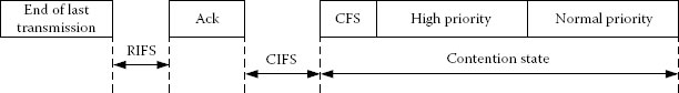
FIGURE 11.3
Priority contention windows. (From Narrowband orthogonal frequency division multiplexing power line communication transceivers for G3-PLC networks, ITU-T Rec. G.9903, October 2012. [Online] Available: http://www.itu.int/rec/T-REC-G.9903 (Fig. C-3). With permission.)
Prioritised access to the channel is specified in G.9903 with two levels of priority (high and normal). Priority resolution is implemented by using two contention time windows during the contention state as shown in Figure 11.3.
The first slot of the CW is called the contention-free slot (CFS). The CFS will be used for transmission of subsequent segments of a MAC packet without the back-off procedure to prevent possible interruption from other nodes and to simplify the MAC packet reassembly procedure for a receiver. In this case, only the first segment is sent using either a normal-priority CW (NPCW) or high-priority CW (HPCW) and the rest are sent using the CFS. The high-and normal-priority stations will compete for channels during the HPCW and normal NPCW correspondingly. Since the HPCW is located before the NPCW, high-priority stations will get access to the channel before the station with normal priority.
Automatic repeat request is implemented based on acknowledged and unacknowledged retransmission. The ACK is a positive acknowledgement that when received allows the transmitter to assume successful delivery of the frame. The negative acknowledgement (NACK) is used to inform a packet originator that the receiver received the packet but it was corrupted. If the originator does not receive an acknowledgement after a waiting period, it assumes that the transmission was unsuccessful and retries the frame transmission in the correct CP. If an acknowledgement is still not received after several retries, the originator can choose either to terminate the transaction or to try again.
11.4.2.2 IPv6 Adaptation Sublayer
G.9903 uses IPv6 as an interconnection scheme at the network layer and adopted 6LoWPAN to facilitate IPv6 interaction at low-rate networks. 6LoWPAN allows power line networks to incorporate IPv6 in embedded equipment and seamless connection of MAC layer and network layer to achieve the header compression, routing, fragmentation and assembly.
To maintain good performance despite the hostile PLC environment, it is essential to adopt an efficient routing protocol over 6LoWPAN which can quickly adapt to varying network topologies and link conditions. G.9903 relies on the 6LoWPAN Ad hoc On-Demand Distance Vector Routing (LOAD) L2 routing protocol defined in [28]. LOAD is a simplified on-demand routing protocol based on Ad hoc on Demand distance Vector routing (AODV) [31]. It is a reactive protocol, and operates creating a mesh network topology underneath the IPv6 network layer.
The route to a destination is found by broadcasting Route Requests (RREQs) per demand, and each node learns about its neighbour node through which it can connect to the destination. Upon reception of RREQ at a destination, the destination node will unicast a Route Reply (RREP) back to the source node using the reverse path characterized by the lowest route cost. Moreover, should a node detect a broken link a Route Error (RERR) is broadcasted to initiate a new source discovery process.
Since LOAD was originally designed for wireless networks, a number of enhancements are specified in G.9903 to improve LOAD’s performance in a PLC network. For example,
• Asymmetrical routes: In PLC, the link between two nodes can be highly asymmetrical, meaning that the quality of the channel is significantly different depending on the communication direction. This is due to the possible proximity of noise sources or mismatch between transmitter and receiver impedances. There is no provision in LOAD to allow communicating the reverse channel quality to an intermediate node so that it can be taken into account in its link cost calculation. Furthermore, LOAD does not specifically propose any method to calculate the link cost between nodes. G.9903 solves this by defining mathematically the link cost on the basis of several parameters and also defines a neighbouring table with entries that include the forward and reverse link cost.
• Forwarding multiple RREQs: Sometimes RREQs can be delayed due to processing load at a node, so that it is not necessarily true that the first RREQ to arrive at an intermediate node has the best route. However, LOAD does not consider this case and subsequent RREQs are not rebroadcasted. This issue is addressed in G.9903 by rebroadcasting late RREQs if their associated route cost is lower than the last rebroadcasted one.
• Minimising sending RREPs: The destination node generates a RREP in response to every RREQ if its route cost is lower than the previously received RREQs from the same source with same RREQ ID. This results in sending multiple RREP through multiple routes. As a consequence, the source needs to wait for some time to make sure that there is no better RREP in transit. In order to reduce the RREP traffic, G.9903 moved the waiting period for collecting all RREPs at the source to the destination. After receiving first RREQ, the destination will wait for a defined period to make sure no other RREQ with a better route cost is in transit. At the end of this wait period, the best route is chosen and a RREP associated with that route is generated and sent toward the source.
• Orphan node: An orphan node is defined as a device that is associated to a network, and, although it had at some time a very good link with the concentrator, it now has a very bad link with the concentrator. In this scenario, the orphan node erroneously believes it has a good route to the data concentrator and this condition may exist for some time before the node or concentrator notices the failure in the link because in AMI applications, there is infrequent access to the meter. Now, since the orphan node always responds to any beacon request from a new associating device, a series of repeated failures of the association procedure for that device can occur. To alleviate this problem, G.9903 specifies a route cost to coordinator field which is added to the payload of the beacon response. Once the first association through an orphan node fails, a very high value of the route cost to coordinator is reported in any future beacon responses of the orphan node. The device seeking to join the network can use this information to avoid selecting the orphan node for the next association attempt.
11.4.2.3 The 2013 G.9903 Revision and LOADng
As mentioned in Section 11.4, the ITU-T approved in May 2013 a Revision of G.9903. One of the main changes in this Revision is the replacement of the routing algorithm LOAD with LOADng [24].
LOADng is designed to further enhance LOAD with additional features and capabilities. Derived from AODV [31], the basic operation of LOADng is similar to LOAD and includes generation of RREQs by a LOADng router, forwarding them until they reach the destination, generation of RREPs upon receipt of an RREQ by the indicated destination and hop-by-hop forwarding of these unicast RREPs toward the originator. It also employs RERR message to report a broken link if a data packet cannot be forwarded. Compared to AODV, LOADng contains both extensions and simplification and it also includes features that are useful in a PLC environment.
Here are some of additional features of LOADng:
• Blacklisting: The blacklisted neighbour set maintains the address of nodes to which the connection is detected to be unidirectional. More specifically, if a node sends a RREP to a neighbour from which a RREQ has been received and the RREP fails, then the neighbour is added to the blacklist. When a neighbour is blacklisted, any RREQ received from that node is dropped.
• Separate forward and reverse route: LOADng introduces provisions to establish different routes between two nodes based on the initiator of the route discovery and hence to create and use two separate routes between two nodes, A and B depending on the direction of communication. This allows the discovery of an optimised route for sending packets from A to B while having a viable link from B to A; and a different optimised route for sending packets from B to A is also found, while having a viable link from A to B.
• Extension for route cost calculation: LOADng allows 16-bit values to be used for route metrics while LOAD only allocates 8 bits. This allows a better resolution when comparing route costs and it also allows for a higher number of hops to be used when accumulating the link costs along a route.
• Optimized flooding is supported, reducing the overhead incurred by RREQ generation and flooding. When a node receives an RREQ looking for a path to a destination address already contained in its routing table, it may propagate the RREQ in an unicast manner to the final destination node avoiding unnecessary flooding.
A preliminary performance evaluation has been conducted in [32], and it has shown that LOADng yields comparative performance to that of AODV except that LOADng incurs a substantially lower control traffic overhead.
An end device may not access the network without a preliminary identification and authentication which are based on two parameters that are unique to the end device:
• An Extended Unique Identifier (EUI-48) MAC address. This address may be easily converted into an EUI-64, if requested.
• A 128-bit shared secret (also known as pre-shared key) used as a credential during the authentication process. It is shared by the ED itself (also known as peer) and an authentication server. The mutual authentication is based on proof that the other party knows the pre-shared key.
The authentication process is extensible authentication protocol–pre-shared key (EAP-PSK) method in place. Confidentiality and integrity services are ensured at different levels at the MAC level and at the EAP-PSK level. At the MAC level, a CCM type of ciphering is delivered to every frame transmitted between nodes in the network. The MAC frames are encrypted and decrypted at every hop. To support this service, all the nodes in the network receive the same group master key which is individually and securely distributed to every node by using the EAP-PSK secure channel.
11.5 Recommendation ITU-T G.9904: PRIME
The PRIME technology was originally conceived within the PRIME Alliance [5]. ITU-T Members of the PRIME Alliance brought the PRIME specifications v. 1.3.6 into the ITU-T, and the specifications were ratified as Recommendation ITU-T G.9904. There are several published papers on PRIME (see [7,9–11].
The reference model of G.9904 is shown in Figure 11.4.
The convergence layer (CL) classifies traffic associating it with its proper MAC connection. This layer performs the mapping of any kind of traffic to be properly included in MAC service data units (MSDUs). It may also include compression functions. Several SSCSs are defined to accommodate different kinds of traffic into MSDUs. The MAC layer provides core MAC functionalities of system access, bandwidth allocation, connection establishment/maintenance and topology resolution. The PHY layer transmits and receives MPDUs between neighbour nodes.
A G.9904 system is composed of subnetworks, each of them defined in the context of a transformer station. A G.9904 subnetwork can be logically seen as a tree structure with two types of nodes: the base node (master) and service nodes (slaves).
A base node is at the root of the tree structure and acts as a master node that provides all network elements with connectivity. It manages the network resources and connections. There is only one base node per G.9904 network.
The service nodes are either leaves or branch points of the tree structure. They are initially in a disconnected functional state and follow the registration process to become part of the network. Service nodes have two functions in the network: keeping connectivity to the other nodes in the network for their application layers and switching other nodes’ data to propagate connectivity.
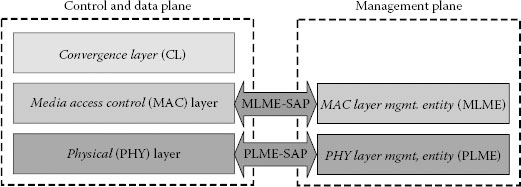
FIGURE 11.4
Reference model of G.9904 protocol layers. (From Narrowband orthogonal frequency division multiplexing power line communication transceivers for PRIME networks, ITU-T Rec. G.9904, October 2012. [Online] Available: http://www.itu.int/rec/T-REC-G.9904 (Fig. 6-1). With permission.)
G.9904 specifies only a CENELEC-A bandplan. This bandplan specifies the use of the frequencies in the 41,992–88,867 kHz range, with carrier spacing of 488.28125 Hz. The three FCC bandplans are FCC-1 (154.6875–487.5 kHz), FCC-1.a (154.687–262.5 kHz) and FCC-1.b (304.687–487.5 kHz), all with carrier spacing of 4.6875 kHz.
G.9904 uses OFDM without any transmitter windowing and with the following set of programmable parameters:
• Number of carriers: 256, of which 96 carry data and 1 is a pilot
• Carrier spacing: 488.28125 Hz
• Carrier modulation: DPSK with 1, 2 or 3 bits per carrier. As opposed to G.9903, G.9904 specifies differential modulation in the frequency domain, that is, the information is encoded in the phase difference between adjacent subcarriers
• Guard interval: 0 for the frame header and 192 μs for the payload
• Size of transmitter windowing: 0 samples
Performing differential encoding in the frequency domain as opposed to in the classical time domain allows better resiliency to impulse noise but also presents other challenges due to the necessity of placing a reference symbol in every first subcarrier of each OFDM symbol. For example, the necessity of placing a reference symbol after every notched carrier introduces overhead reducing transmission efficiency and G.9904 deals with this by not allowing to turn off subcarriers. This is a limitation when dealing with channels affected by narrowband interferers.
G.9904 allows the transmission of a variable number of OFDM symbols per PHY frame, up to 63.
G.9904 specifies a convolutional encoder with rate 1/2 and constraint length L = 7, which is the same as the one used in G.9902 and G.9903. There is no RS encoder and the convolutional encoder can be turned off. G.9904 specifies a channel interleaver but, differently from G.9903, interleaving is done within a single OFDM symbol.
Similarly to G.9902 and G.9903, G.9904 specifies the adaptive selection of usable tones and optimum modulation and code rate to maximise throughput.
11.5.1.5 Channel Estimation and Pilot Tones
In a differential scheme, channel estimation is not needed. Nevertheless, G.9904 specifies 13 pilots in the header to facilitate the estimation of the frequency offset and one pilot to provide a phase reference for frequency domain DPSK demodulation.
No robust mode is defined in G.9904.
11.5.2.1 Medium Access Control
G.9904 devices access the channel based on dividing time into composite units of abstraction for channel usage, called MAC frames. The service nodes and base node on a network can access the channel in the shared contention period (SCP) or request a dedicated contention-free period (CFP). CFP channel access needs devices to request allocation from the base node. Depending on channel usage status, the base node may grant access to the requesting device for a specific duration or deny the request. SCP channel access does not require any arbitration. However, the transmitting devices need to respect the SCP timing boundaries in a MAC frame. The composition of a MAC frame in terms of SCP and CFP is communicated in every frame as part of the beacon. A MAC frame is comprised of one or more beacons, one SCP and zero or one CFP (see Figure 11.5).
G.9904 also specifies a L2 mechanism for routing within a G.9904 network. If the base node cannot communicate with a node directly, switch nodes relay traffic to/from the base node so that every node on the network is effectively able to communicate with the base node. Switch nodes selectively forward traffic that originates from or is destined to one of the service nodes in its control hierarchy. All other traffic is discarded by switches, thus reducing traffic flow on the network. Switch nodes do not necessarily need to connect directly to the base node. They may attach to other switch nodes and form a cascaded chain. There is no limitation to the number of switch nodes that may connect to a switch node down the cascaded chain, thus contributing significantly to range extension and scalability.
The CL classifies traffic associating it with its proper MAC connection. The CL is separated into two sublayers:
1. The common part convergence sublayer (CPCS) provides a set of generic services.
2. The service-specific convergence sublayer (SSCS) contains services that are specific to one application layer.
There may be several SSCS, but only one common part CPCS. Several CLs are defined in order to accommodate different kinds of traffic: IPv4 and IPv6 CL and IEC 61334-4-32 [33] as a link toward metering systems.
G.9904 security provides privacy, authentication and data integrity to the MAC layer through a secure connection method and a key management policy.
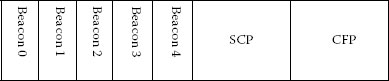
FIGURE 11.5
Structure of a MAC frame. (From Narrowband orthogonal frequency division multiplexing power line communication transceivers for PRIME networks, ITU-T Rec. G.9904, October 2012. [Online] Available: http://www.itu.int/rec/T-REC-G.9904 (Fig. 8-7). With permission.)
While devices may choose not to encrypt data traffic, it is mandatory for all MAC control messages to be encrypted with a specific security profile. Several security profiles are provided to manage different security needs, which can arise in different network environments. Current G.9904 version specifies two security profiles.
Authentication is guaranteed by the fact that each node has its own secret key known only by the node itself and the base node. Data integrity is guaranteed by the fact that the payload CRC itself is encrypted. Communications having Security Profile 0 are based on transmission of MAC frames without any encryption. This profile will be used by communication that does not have strict requirements on privacy, authentication or data integrity. Security Profile 1 is based on 128 bit AES encryption of data and its associated CRC.
An additional critical effort taken by the IEEE P1901.2 Draft is the definition of a robust and reliable coexistence mechanism. Coexistence is meant to address the issue of interference between non-interoperable devices that share the same power line cable. Power line cables connect LV transformers to a set of individual homes or set of multiple dwelling units without isolation. Signals generated within the premises interfere among each other, and with signals generated outside the premises. As the interference increases, both from indoors and outdoors sources, PLC stations will experience a decrease in data rate as packet collisions increase, or even complete service interruption. Hence, PL cables are a shared medium (like coax and wireless) and do not provide links dedicated exclusively to a particular subscriber. As a consequence, the PLC channel is interference limited, and approaches based on frequency division multiplexing as in Wi-Fi or coax are not always suitable because only a relatively small band is available in PLC. As a consequence, it is necessary to devise mechanisms to limit the harmful interference caused by non-interoperable neighbouring devices. Note that similar considerations can be made about the interference-limited nature of many wireless networks, for example, Wi-Fi, WiMAX, Zigbee, Bluetooth, and Z-Wave (as treated in [34]).
The issue of PLC coexistence was first raised two decades ago in CENELEC. Since CENELEC did not mandate the use of a specific PHY/MAC, it was necessary to provide a fair channel access mechanism that avoided channel capture and collisions when non-interoperable devices operated on the same wires. In fact, if non-interoperable devices access the medium, then native CSMA and virtual carrier sensing do not work and a common medium access mechanism must be defined. CENELEC mandates a CSMA/CA mechanism only for the C-band [35] where a single frequency (132.5 kHz) is used to inform that the channel is in use.
The use of orthogonal bandplans enables one form of coexistence (frequency separation) Another coexistence mechanism utilises a notching technique, also referred to as tone masking. Notching is a method to avoid certain frequencies that are reserved by power line regulatory bodies for other applications; it also allows for cohabitation with singlecarrier NB-PLC [2,3] systems and cohabitation with other potential systems operating over the power line. However, to meet the IEEE 1901.2 objective of developing a complete coexistence mechanism, additional mechanisms are required.
11.6.1 IEEE P1901.2 Preamble-Based Coexistence
The requirement of defining a NB-PLC coexistence between IEEE P1901.2 and the three technologies specified in ITU-T (G.hnem, G3-PLC, PRIME) was raised in the SGIP/US National Institute of Standards and Technology (NIST) Priority Action Plan (PAP) 15 Group [36]. It was also agreed in PAP 15 that the NB-PLC mechanism should be future proof, so that future technologies could also coexist with today’s. The IEEE P1901.2 Working Group took the responsibility to work on a preamble-based coexistence mechanism tailored for NB-PLC OFDM-based solutions. This preamble-based coexistence mechanism allows different NB-PLC solutions to coexist with fairness and minimal disruption of service.
A preamble-based CSMA coexistence mechanism employs a fixed number of coexistence preamble symbols at a specific frequency, or multiples of a specific frequency depending on the bandplan. Fairness can be achieved through the appropriate sequence of repeated coexistence preambles over a given time duration, and through a defined duty cycle which enables a defined time to occupy the channel (whether same technology or different NB-PLC solutions).
To implement a coexistence procedure, several configuration parameters need to be set. These parameters determine channel access and the amount of time that a channel can be controlled. Additionally, coexistence behaviour/fairness attributes need to be defined with type, range, description and default values. The use of a coexistence mechanism is dependent on the technology type and region of deployment. Control attributes are defined to set default values that enable or disable the preamble-based coexistence mechanism. For example, an IEEE P1901.2 solution implementing only a CENELEC-A bandplan in a region where energy providers control the CENELEC-A frequency band could most likely not implement the preamble-based coexistence mechanism because the probability that the same utility deploys non-interoperable NB-PLC devices is negligible. Instead, the solution would rely on existing frequency separation or notching techniques.
G.9902 supports three types of coexistence:
1. Frequency division: Allows the suppression of interference from G.9902 into a particular frequency band or bands by using non-overlapping ITU-T G.9902 bandplans.
2. Frequency notching: Allows to suppress interference from G.9902 into a particular (relatively narrow) frequency range by notching out one or more subcarriers; frequency notching allows G.9902 to coexist with the existing narrowband FSK/PSK systems operating over the same frequency band.
3. Preamble-based: Allows to fairly share the medium with other types of PLC technologies operating over the same frequency band (and utilising this coexistence mechanism).
G.9902 states that support for coexistence is mandatory, while G.9903 states that a preamble-based coexistence mechanism is mandatory with the exception of when the network is operated in frequency bands restricted to monitoring or controlling the operation of the grid (e.g. CENELEC-A band), in which case coexistence is optional. G.9904 contains no language on coexistence.
11.7 A Qualitative Comparison of NB-PLC Technologies
The four HDR NB-PLC standards described in this chapter present some similarities but also marked differences. While at the MAC level they all use some variant of CSMA/CA, the PHY exhibits many differences in the design choices. Also the support for routing at L2 or L3 is a philosophical divide that puts on one side G.9903 and G.9904 in support of L2 routing and on the other side IEEE P1901.2 and G.9902 agnostic with respect to routing and capable of supporting it at both L2 and L3.
In the following sections, the major differences between these four standards will be highlighted and discussed qualitatively.
The main PHY parameters of the four HDR NB-PLC discussed earlier are listed in Tables 11.2 and 11.3 for the CENELEC-A and FCC bandplans, respectively. The maximum data rates take into account of cyclic prefix (CP), FEC and the overhead of FCH, preambles, CES and pilots. Similar values for these data rates are also reported in [23]. Note that the data rates shown in the tables are the maximum ones achievable over an ideal channel. Actual data rates will be lower and depend on line conditions.
11.7.1.1 NB-PLC Channel Assumptions
When designing transceivers, one of the first things one has to have is knowledge about the physical channel. When comparing these four technologies, the first difference that can be observed is that some choices indicate that designers made very different assumptions about the NB-PLC channel. For example, the guard interval ranges from 55 to 192 μs in CENELEC-A and from 18.3 to 60 μs for the FCC band; this clearly shows that the various designers had very different assumptions about the frequency selectivity of the NB-PLC channel. Making a mistake on the level of ISI introduced by the channel can cause a reduction of the available SNR, something that may be critical in certain scenarios characterised already by low SNR or that may prevent the use of higher-order constellations.
PHY Parameters of NB-PLC Solutions and Their Maximum Data Rate – CENELEC-A Bandplan
ITU-T G.9902 (G.hnem) |
ITU-T G.9903 (G3-PLC) |
ITU-T G.9904 (PRIME) |
IEEE P1901.2a |
|
Frequency range (kHz) |
35.9–90.6 |
35.9–90.6 |
42–89 |
35.9–90.6 |
Sampling frequency (kHz) |
200 |
400 |
250 |
400 |
Number of carriers |
128 |
128 |
256 |
128 |
Cyclic prefix (μs) |
100/160 |
75 |
192 |
75 |
Guard interval (μs) |
60/120 |
55 |
192 |
55 |
Window size (samples) |
8 |
8 |
0 |
8 |
Subcarrier spacing (Hz) |
1562.5 |
1562.5 |
488.28125 |
1562.5 |
OFDM symbol duration (μs) |
700/760 |
695 |
2240 |
695 |
Modulation |
M-QAM |
M-DPSKb |
M-DPSK |
M-DPSK |
FEC |
Conv+RS |
Conv+RS |
Convc |
Conv+RS |
Interleaving over |
Fragment/AC cycle |
Packet |
OFDM symbol |
Packet |
Robust modes |
Yes |
Yes |
No |
Yes |
PHY frame efficiency |
Multiple RS |
Single RS |
≤63 symbols |
Single RS |
Max PHY rate for M = 2 (kbps) |
25.3 |
20.3 |
20.5 |
20.0 |
Max PHY rate for M = 4 (kbps) |
50.6 |
34.9 |
41.0 |
34.1 |
Max PHY rate for M = 8 (kbps) |
76.0 |
46.0 |
61.4 |
44.6 |
Max PHY rate for M = 16 (kbps) |
101.3 |
N/A |
N/A |
N/A |
a At the time of writing, specifications can change before approval.
b Differential modulation is mandatory, and an optional coherent mode has been specified in Revised G.9903.
c The convolutional code in PRIME is optional.
PHY Parameters of NB-PLC Solutions and Their Maximum Data Rate – FCC Bandplan.
ITU-T G.9902 (G.hnem) |
ITU-T G.9903 (G3-PLC) |
IEEE P1901.2a |
|
Frequency range (kHz) |
34.4–478.1/150–478.1b |
154.7–487.5 |
154.7–487.5 |
Sampling frequency |
800 kHz |
1.2 MHz |
1.2 MHz |
Number of carriers |
256 |
128 |
128 |
Cyclic prefix (ps) |
50/80 |
25 |
25 |
Guard interval (ps) |
30/60 |
18.3 |
18.3 |
Window size (samples) |
16 |
8 |
8 |
Subcarrier spacing (Hz) |
3125 |
4687.5 |
4687.5 |
OFDM symbol duration (ps) |
350/380 |
231.7 |
231.7 |
Modulation |
M-QAM |
M-DPSK/M-QAMc |
M-DPSK/M-QAM |
FEC |
Conv+RS |
Conv+RS |
Conv+RS |
Interleaving over |
Fragment/AC cycle |
Packet |
Packet |
Robust modes |
Yes |
Yes |
Yes |
PHY frame efficiency |
Multiple RS |
Single/Two RSd |
Single/Two RSd |
Max PHY rate for M = 2 (kbps) |
210.2/150.8 |
106.2 |
106.2 |
Max PHY rate for M = 4 (kbps) |
417.4/301.6 |
166.5c |
166.5c |
Max PHY rate for M = 8 (kbps) |
616.5/448.1 |
207.6c |
207.6c |
Max PHY rate for M = 16 (kbps) |
809.5/591.0 |
233.5c |
233.5c |
a At the time of writing, specifications can change before approval.
b Data rates values are shown for the FCC and FCC-2 bandplans, respectively.
c Differential modulation is mandatory, but an optional coherent mode is specified in G.9903.
d For the data rate calculation, it is assumed that only a single RS code word can be transmitted in a frame – as in the current Revised G.9903. Both the current IEEE P1901.2 Draft and an Amendment of G.9903 under development specify the use of two RS code words per frame in the FCC bandplan.
Also, choices about robustness against channel noise denote a really diverse set of assumptions on the channel. For example, we go from the G.9904 (PRIME) ‘optimism’ where a simple convolutional encoder is used (and can also be turned off), no robust mode is specified and interleaving is made within a single OFDM symbol, to the much more conservative choices of G.9903 (G3-PLC) where a concatenated coding scheme is employed, interleaving is done over the whole packet and two robust modes are specified. Furthermore, while G.9902 and G.9904 allow to transmit frames constituted of multiple RS code words or multiple OFDM symbols, G3-PLC designers decided to improve impulse noise protection by constraining transmission efficiency and allowing the transmission of a single RS code word per packet only.
Another difference worth mentioning is that the differential modulation specified in G.9903 is different from the differential modulation specified in G.9904. The former is the classical ‘time-differential’ phase modulation (t-DPSK), that is, the information is encoded in the phase difference between two consecutive symbols; the latter is a ‘frequency-differential’ phase modulation (f-DPSK) where the information is encoded in the phase difference between adjacent subcarriers, respectively. These two differential modulations yield the same performance in additive white Gaussian noise (AWGN) or block fading channels but behave differently in more realistic channels. In fact, erasures in time like impulse noise affect t-DPSK more than f-DPSK, but the opposite holds for erasures in the frequency domain like narrowband interferers. Furthermore, different interleaver and FEC design will also contribute to the overall PHY performance.
Hoch compared the PHY performance of G.9903 and G.9904 and reported the following conclusions [11]:
• In frequency flat channels affected by coloured and periodic impulsive noise, G.9903 performs better than G.9904 because of the additional RS coding. For example, at a frame error rate (FER) of 10−4, the SNR gain of G.9903 is around 6 dB.
• In frequency-selective channels and AWGN, G.9903 performs again better than G.9904 for DBPSK, while for higher constellations, performances tend to be similar. This may be due to the fact that bad channels (high ISI) affect higher-order constellations of the two systems in a similar way.
• In frequency flat channels affected by AWGN and a narrowband interferer, G.9903 outperforms G.9904 and in some cases G.9904 is degraded so much that communications is not possible.
Finally, while it has been shown that G3-PLC is able to penetrate LV/MV transformers [12] thus ensuring LV to MV and MV to LV connectivity, here are no publicly available reports that confirm that PRIME signals can pass the distribution transformer. The capability of passing LV/MV transformers offers more degrees of freedom in network design. The main architectural consequence of MV/LV connectivity is that many more meters could be handled by a single concentrator located on the MV side. This concentrator node would then send the aggregated data from many meters back to the utility using either PLC or any other networking technology available in situ. This capability also heavily impacts the business case when there is a very different number of customers per MV/LV transformer: in North America, the majority of transformers serves less than 10 customers; in Europe, the majority of transformers serves 200 customers or more. Thus, especially in the United States, it is economically advantageous to avoid coupler installation and resort to technologies that allow connectivity between the MV and LV sides – and possibly also between meters served by different distribution transformers (LV/MV/LV links). When there are very few end points (meters) per distribution transformer as in the United States, it is convenient to push the concentrator up along the MV side (and even up to the substation) and handle multiple LV sections so that more end points can be handled per concentrator. On the other hand, the large number of end points per transformers in Europe does not really require to locate the concentrator up in the substation or on the MV side as it can be conveniently located on the LV section of the grid. Thus, the capability of a NB-PLC technology to pass through distribution transformers is very appealing in areas with low density of population (meters).
11.7.1.2 Coherent versus Differential Modulation
Another interesting difference is given by the choice of differential modulations or PSK/QAM modulation. G.9902 (G.hnem) specifies a mandatory PSK/QAM modulation, while G.9903 (G3-PLC), G.9904 (PRIME) and IEEE P1901.2 specify a mandatory (time or frequency) differential modulation. The choice of specifying PSK/QAM modulations for G.hnem influenced also the other groups, although no public results of the performance of these modulations in the field are today available. For example, while G3-PLC was being discussed in ITU-T, an additional optional coherent modulation was specified for both CENELEC-A and FCC bandplans. Similarly, also the IEEE P1901.2 Working Group that originally specified only the differential modulation used in G3-PLC, decided to add an optional coherent mode.
The basic principle of differential modulation (which is a particular case of modulation with memory) is to use the phase of the previous symbol as reference of the current symbol. In AWGN, the SNR gain of coherent versus incoherent reception is nearly 3 dB, while for Rayleigh slow fading channels it is a little bit <3 dB (at high SNR). Recent work has shown that there are non-coherent decoding schemes that can be applied to almost all types of coded modulation and can approach the performance of coherent detection over AWGN as the observation length grows (see [37]). However, this property does not hold true for channels affected by non-Gaussian noise like the PLC one which is often modelled as an erasure channel. In fact, as the PLC channel is affected by periodic impulse noise, letting the observation length grow to improve non-coherent detection raises also the probability of occurrence of an erasure that will then cause a loss in the memory of the differential modulation. Since an erasure may destroy the memory required for differential decoding, a loss of the reference phase in the previous symbol may occur thus leading to the incorrect detection of the current symbol. Furthermore, even if differential modulation copes well with random shifts of the carrier phase (thus allowing non-coherent demodulation), it does not perform well when the channel has a non-zero Doppler spread* as in the case of PLC [38]. In fact, in this case, the signal phase can lose its correlation between consecutive symbols making the previous symbol a noisy phase reference. Thus, in a severely impulsive channel, the SNR gain of coherent reception over non-coherent may grow beyond the classical 3 dB in AWGN as the erasure probability of the channel grows.
These theoretical considerations can justify the preference for a coherent scheme, and they are also consistent with the results reported in [40], where it was shown that non-coherent schemes suffer performance degradation when the channel is time varying and affected by impulsive noise. The issue of how much gain coherent reception can offer with respect to incoherent reception over the PLC channel and for the many NB-PLC application scenarios still requires further analysis and field testing, and this can explain why certain groups have decided not to specify at all a coherent mode (G.9904) or to specify it just as an option (G.9903 and IEEE P1901.2). Nevertheless, it is an interesting problem that the scientific community should tackle. Of course, it is also true that doing so is problematic because there is no commonly agreed upon NB-PLC channel model.
11.7.2 ‘Route-Over’ or ‘Mesh-Under’?
As mentioned earlier, the support in NB-PLC standards for routing at L2 (mesh-under) or L3 (route-over) is still an open problem, and it is not clear yet what the best approach is for the various Smart Grid applications. A mesh-under approach places routing functions in the link layer to emulate a single broadcast domain where all devices appear as immediate neighbours to the network layer (e.g. for G.9903 devices, every node is at one IPv6 hop from each other), even if this is not the case and multi-hop communication still occurs. In contrast, a route-over approach places all routing functions at the network layer thus following the classical IP architecture.
In choosing between L2 and L3 routing, scalability is the first issue. In L3 routing with IP, there is aggregation at the IP prefix level, and, therefore, solutions are scalable. On the other hand, one can design a L2 addressing and routing scheme that is very much similar to an L3 one, the only difference will be in address assignment and whether it is possible to aggregate addresses and create routing tables that scale well. Another aspect to consider is overhead: IP packets add a 40 byte header to a L2 packet, and this can be as high as 20% of the data payload carried by a G.9903 or IEEE P1901.2 packet. Answering this question in general is not easy as the assumed topological characteristics of the network and the traffic flowing through it can yield different conclusions. As more experimental validation is certainly needed, here we will review the recent literature on this topic and point out what is important with respect to AMI applications over PLC. We will also restrict our overview to the comparison of LOADng [24] and RPL [25], which are the main candidates proposed for Smart Grid applications.
LOADng and RPL are two good solutions for routing, but perhaps they solve two different problems [41]. RPL is highly optimised for specific topologies where multi-point-to-point (MP2P) traffic dominates (e.g. wireless sensor networks) and a central controller handles topology formation and maintenance. On the other hand, the philosophy underlying LOADng allows a distributed mode of operation where paths are discovered on demand and bidirectional traffic–P2P, MP2P and point-to-multi-point (P2MP)–is present. For many Smart Grid applications, including AMI, the assumption of bidirectional traffic is closer to reality*.
The simulation study in [42] evaluates the quality of RPL routes for the case of point-to-point traffic. For this scenario, it was found that the path quality of RPL is fairly close to an optimised shortest path. However, AMI traffic requires both MP2P and P2MP links. The performance of the RPL routing protocol with bidirectional traffic is investigated in [43], and it is reported that LOAD can provide similar data delivery ratios as RPL but with less protocol overhead. Additional experimental results on RPL are reported in [44] for a wireless network, confirming its good performance; and recent experimental results on advanced LOAD that confirm its good performances have been reported in [45].
In the work by Ancillotti et al. [6,7], it is reported that RPL route selection procedures ensures to find dominant routes that are significantly persistent and dominated by a single route, and this may prevent RPL from quickly adapting to link quality variations which is very common scenario in PLC-based networks. It was also found that RPL lacks a complete knowledge of link qualities, and it may sometimes select suboptimal paths with highly unreliable links. The authors also conclude that further research is required to improve the RPL route selection process in order to increase routing reliability.
It is finally important to point out that most results available in the literature pertain to wireless sensor networks and the specific characteristics of PLC links (low throughput, time varying and asymmetric link quality, unidirectional links – see also Section 11.4.2.3) are not always taken into account. Thus, we remind the reader about the general caveat that generalisation from simulation studies should always be made cum grano salis.
The design intent for G.9902 was to integrate features of G3-PLC and PRIME and add new features for even better performance. However, there are no experimental results on G.9902 today, so it is not possible yet to say whether that goal was achieved or not. G3-PLC was originally designed for improved robustness sometimes at the cost of reduced data rate, which is a reasonable design choice as HDR is not the primary design goal in smart metering applications–see also considerations made in Sect. V.D of [4]. The G.9903 and IEEE P1901.2 approach was to build on top of the original G3-PLC PHY and enhance it. Several G3-PLC field trials have been going on for years, thus allowing a lot of fine-tuning and improvements that have been included in both G.9903 and IEEE P1901.2. However, while the experience gathered with the LOAD and LOADng routing mechanisms has been retained in G.9903, IEEE P1901.2 and G.9902 have not specified any L2 or L3 routing scheme. Finally, G.9904 was originally designed for simplicity, keeping in mind a combination of robustness and data rate.
1. Open data communication in building automation, controls and building management – Control network protocol, ISO/IEC Std. DIS 14908, 2008.
2. Distribution automation using distribution line carrier systems – Part 5-2: Lower layer profiles – Frequency shift keying (S-FSK) profile, IEC Std. 61334-5-2, 1998.
3. Distribution automation using distribution line carrier systems – Part 5-1: Lower layer profiles – Spread frequency shift keying (S-FSK) profile, IEC Std. 61334-5-1, 2001.
4. S. Galli, A. Scaglione and Z. Wang, For the grid and through the grid: The role of power line communications in the Smart Grid, Proc. IEEE, 99(6), 998–1027, June 2011.
5. Powerline Related Intelligent Metering Evolution (PRIME). [Online] Available: http://www.prime-alliance.org, accessed 13 October 2013.
6. The G3-PLC Alliance. [Online] Available: http://www.g3-plc.com/.
7. I. Berganza, A. Sendin and J. Arriola, Prime: Powerline intelligent metering evolution, in IET- CIRED – CIRED Seminar, SmartGrids for Distribution, Frankfurt, Germany, 23–24 June 2008.
8. K. Razazian, M. Umari, A. Kamalizad, V. Loginov and M. Navid, G3-PLC specification for powerline communication: Overview, system simulation and field trial results, in IEEE International Symposium on Power Line Communications and Its Applications (ISPLC), Rio de Janeiro, Brazil, 28–31 March 2010.
9. I. Berganza, A. Sendin, A. Arzuaga, M. Sharmaand and B. Varadarajan, PRIME interoperability tests and results from field, in IEEE International Conference on Smart Grid Communications (SmartGridComm), Gaithersburg, MD, 4–6 October 2010.
10. J. Domingo, S. Alexandres and C. Rodriguez-Morcillo, PRIME performance in power line communication channel, in IEEE International Symposium on Power Line Communications and Its Applications (ISPLC), Udine, Italy, 3–6 April 2011.
11. M. Hoch, Comparison of PLC G3 and PRIME, in IEEE International Symposium on Power Line Communications and Its Applications (ISPLC), Udine, Italy, 3–6 April 2011.
12. K. Razazian, A. Kamalizad, M. Umari, Q. Qu, V. Loginov and M. Navid, G3-PLC field trials in U. S. distribution grid: Initial results and requirements, in IEEE International Symposium on Power Line Communications and Its Applications (ISPLC), Udine, Italy, 3–6 April 2011.
13. IEEE 1901.2: Draft Standard for Low Frequency (less than 500 kHz) Narrow Band Power Line Communications for Smart Grid Applications. [Online] Available: http://grouper.ieee.org/groups/1901/2, accessed 13 October 2013.
14. ITU-T Question 15/15 – Communications for Smart Grid. [Online] Available: http://www.itu.int/en/ITU-T/studygroups/2013-2016/15/Pages/q15.aspx, accessed 13 October 2013.
15. SAE J2931/3 - PLC Communication for Plug-in Electric Vehicles. [Online] Available: http://standards.sae.org/wip/j2931/3, accessed 13 October 2013.
16. Road vehicles – Vehicle to grid Communication Interface – Part 3: Physical and data link layer requirements, ISO/IEC Std. ISO/DIS 15118-3, 2013.
17. Narrowband OFDM power line communication transceivers – Physical layer specification, ITU-T Rec. G.9955, December 2011.
18. Narrowband OFDM power line communication transceivers – Data link layer specification, ITU-T Rec. G.9956, November 2011.
19. Narrowband orthogonal frequency division multiplexing power line communication transceivers – Power spectral density specification, ITU-T Rec. G.9901, November 2012. [Online] Available: http://www.itu.int/rec/T-REC-G.9901, accessed 13 October 2013.
20. Narrowband orthogonal frequency division multiplexing power line communication transceivers for ITU-T G.hnem networks, ITU-T Rec. G.9902, October 2012. [Online] Available: http://www.itu.int/rec/T-REC-G.9902, accessed 13 October 2013.
21. Narrowband orthogonal frequency division multiplexing power line communication transceivers for G3-PLC networks, ITU-T Rec. G.9903, October 2012. [Online] Available: http://www.itu.int/rec/T-REC-G.9903, accessed 13 October 2013.
22. Narrowband orthogonal frequency division multiplexing power line communication transceivers for PRIME networks, ITU-T Rec. G.9904, October 2012. [Online] Available: http://www.itu.int/rec/T-REC-G.9904, accessed 13 October 2013.
23. M. Nassar, J. Lin, Y. Mortazavi, A. Dabak, I. Kim and B. Evans, Local utility power line communications in the 3–500 kHz band: Channel impairments, noise, and standards, IEEE Signal Process. Mag., 29(5), 116–127, September 2012.
24. T. H. Clausen, A. Colin de Verdiere, J. Yi, A. Niktash, Y. Igarashi, H. Satoh, U. Herberg, C. Lavenu, T. Lys, C. E. Perkins and J. Dean, The Lightweight On-demand Ad hoc Distance-vector Routing Protocol – Next Generation (LOADng), IETF Internet-Draft, 7 January 2013. [Online] Available: http://tools.ietf.org/html/draft-clausen-lln-loadng-07, accessed 13 October 2013.
25. T. Winter, P. Thubert, A. Brandt, J. Hui, R. Kelsey, P. Levis,P. Vasseur and R. Alexander, RPL: IPv6 routing protocol for low-power and Lossy networks, IETF RFC 6550, March 2012.
26. V. Oksman and J. Zhang, G.hnem: The new ITU-T standard on narrowband PLC technology, IEEE Commun. Mag., 49(12), 138–145, December 2011.
27. A. Rossello-Busquet, G.hnem for AMI and DR, in International Conference on Computing, Networking and Communications (ICNC), Maui, HI, 30 January–2 February 2012.
28. K. Kim, S. Daniel Park, G. Montenegro, S. Yoo and N. Kushalnagar, 6LoWPAN Ad Hoc On-Demand Distance Vector Routing (LOAD), IETF Internet-Draft, 19 June 2007. [Online] Available: http://tools.ietf.org/html/draft-daniel-6lowpan-load-adhoc-routing-03, accessed 13 October 2013.
29. IEEE standard for local and metropolitan area networks – Part 15.4: Low-rate wireless personal area networks (LR-WPANs), IEEE Std. 802.15.4, 2006.
30. G. Montenegro, N. Kushalnagar, J. Hui and D. Culler, Transmission of IPv6 Packets over IEEE 802.15.4 Networks, IETF RFC 4944, September 2007. [Online] Available: https://tools.ietf.org/html/rfc4944, accessed 13 October 2013.
31. C. Perkins, E. Belding-Royer and S. Das, Ad hoc on-demand distance vector (AODV) routing, IETF RFC 3561, July 2003. [Online] Available: http://www.ietf.org/rfc/rfc3561.txt, accessed 13 October 2013.
32. T. Clausen, J. Yi and A. de Verdiere, LOADng: Towards AODV version 2, in IEEE Vehicle Technical Conference (VTC), Québec City, Canada, 3–6 September 2012.
33. Distribution automation using distribution line carrier systems Part 4: Data communication protocols Section 32: Data link layer logical link control (LLC), IEC Std. 61334-4-32, 1996.
34. J. J. García Fernández, L. T. Berger, A. Garcia Armada, M. J. Fernández-Getino, V. P. Gil Jiménez and T. B. S orensen, Wireless communications in smart grids, in Smart Grid – Applications, Communications and Security, L. T. Berger and K. Iniewski, Eds. Hoboken, NJ: John Wiley & Sons, April 2012, ch. 6.
35. Signaling on low-voltage electrical installations in the frequency range 3 kHz-148.5 kHz – Part 1: General requirements, frequency bands and electromagnetic disturbances., CENELEC Std. EN 50065-1, 2011.
36. Priority Action Plan (PAP-15): Harmonize power line carrier standards for appliance communications in the home. [Online] Available: http://www.sgip.org/pap-15-power-line-communications/#sthash.e6MzyTB6.dpbs, accessed 13 October 2013.
37. D. Raphaeli, Noncoherent coded modulation, IEEE Trans. Commun., 44, 172–183, February 1996.
38. F. Cañete, J. Cortés, L. Díez and J. Entrambasaguas, Analysis of the cyclic short-term variation of indoor power line channels, IEEE J. Sel. Areas Commun., 24(7), 1327–1338, July 2006.
39. S. Galli and A. Scaglione, Discrete-time block models for transmission line channels: Static and doubly selective cases, 2011. [Online] Available: http://arxiv.org/abs/1109.5382, accessed 13 October 2013.
40. D. Umehara, M. Kawai and Y. Morihiro, Performance analysis of noncoherent coded modulation for power line communications, in International Symposium on Power Line Communications and Its Applications (ISPLC), Malmö, Sweden, 4–6 April 2001.
41. M. P. T. Clausen and U. Herberg, A critical evaluation of the IPv6 routing protocol for low power and Lossy networks (RPL), in IEEE International Conference on Wireless and Mobile Computing, Networking and Communications (WiMob), Shanghai, China, 10–12 October 2011.
42. J. Tripathi, J. de Oliveira and J. Vasseur, Applicability study of RPL with local repair in Smart Grid Substation Networks, in IEEE International Conference on Smart Grid Communications (SmartGridComm), Gaithersburg, MD, 4–6 October 2010.
43. U. Herberg and T. Clausen, A comparative performance study of the routing protocols LOAD and RPL with bi-directional traffic in low-power and lossy networks (LLN), in International Symposium on Performance Evaluation of Wireless Ad Hoc, Sensor, and Ubiquitous Networks (PE-WASUN), Miami Beach, FL, 31 October–4 November 2011.
44. J. P. Vasseur, J. Hui, S. Dasgupta and G. Yoon, RPL Deployment Experience in Large Scale Networks, IETF Internet-Draft, 5 July 2012. [Online] Available: http://tools.ietf.org/id/draft-hui-vasseur-roll-rpl-deployment-01.txt, accessed 13 October 2013.
45. K. Razazian, A. Niktash, T. Lys and C. Lavenu, Experimental and field trial results of enhanced routing based on LOAD for G3-PLC, in International Symposium on Power Line Communications and Its Applications (ISPLC), Johannesburg, South Africa, 24–27 March 2013.
46. E. Ancillotti, R. Bruno and M. Conti, RPL routing protocol in Advanced Metering Infrastructures: An analysis of the unreliability problems, in IFIP Conference on Sustainable Internet and ICT for Sustainability (SUSTAINIT), Pisa, Italy, 4–5 October 2012.
47. E. Ancillotti, R. Bruno and M. Conti, The role of the RPL routing protocol for Smart Grid communications, IEEE Commun. Mag., 51(1), 75–83, January 2013.
*. For payload symbols, two guard intervals are defined. The longest guard interval is used for 16-QAM modulation due to its higher sensitivity to Inter-Symbol Interference (ISI).
*. Cañete et al. [38] measured in indoor PLC channels a median Doppler spread of 100 Hz, a 90% percentile of 400 Hz and Doppler components up to 1750 Hz; thus, the coherence time of the PLC channel is around 600 μs. Interestingly, all observed Doppler components were quantised at multiples of the fundamental frequency of the mains AC cycle, thus suggesting that the PLC channel behaves like a linear and periodically time-varying (LPTV) channel [39]. This LPTV behaviour is due to the fact that the electrical devices plugged in outlets (loads) contain non-linear elements such as diodes and transistors that, relative to the small and rapidly changing communication signals, appear as a resistance biased by the AC mains voltage. In fact, the periodically changing AC signal swings the devices over different regions of their non-linear I/V curve and this induces a periodically time-varying change of their resistance. The overall impedance appears as a shunt impedance across the ‘hot’ and ‘return’ wires and, since its time variability is due to the periodic AC mains waveform, it is naturally periodic. A time-varying (and sometimes even LPTV) behaviour can also be encountered in the LV/MV outdoor PLC channel.
*. Typically, AMI applications require handling up to 10,000 m with both MP2P and P2MP types of traffic: MP2P traffic is due to the support of scheduled read reporting, on-demand meter reading and event-driven responses (e.g. in the case of power outages or leak detections); P2MP traffic is due to the support of meter configuration, meter read requests, network wide firmware upgrades, demand-response applications. In the case of distribution automation, it is also necessary to support point-to-point traffic between a few devices.