
IEEE 1901: Broadband over Power Line Networks*
CONTENTS
13.2 IEEE 1901 In-Home Architecture
13.3 1901 FFT-PHY: A Functional Description
13.3.1 IEEE 1901 FFT-OFDM Preamble Generator
13.3.3 IEEE 1901 FFT-OFDM Turbo Encoder
13.3.4 Frame Control Diversity Copier
13.3.8 Symbol Generation (Cyclic Prefix, Pulse Shaping and Overlap)
13.4 IEEE 1901 In-Home MAC: Functional Overview
13.4.2 Channel Access Mechanisms
13.5 IEEE 1901 FFT-OFDM Access System
13.5.1 Access BPL versus NB PLC
13.6 IEEE 1901 FFT-OFDM Access: System Description
13.6.5 Access Intercell Gateway
13.7 IEEE 1901 FFT-OFDM Access: Channel Access
13.7.1 Channel Access Management
13.8 IEEE 1901 FFT-OFDM Access: Routing
13.8.2 Distance Vector Approach
13.9 IEEE 1901 FFT-OFDM Access: Power Management
The rapid growth of Internet content and media streaming options, coupled with increasing bandwidth of broadband access (AC) technologies, has created an ecosystem of products and services that creates a demand for media in the home. Bottlenecks are the connection into the home and inside the home, wherein the data are forwarded to a gateway or router that has to distribute to various media sinks like televisions, smartphones, tablets, digital video recorders and cable set-top boxes. Wireless distribution is an obvious solution but faces many challenges like spotty whole-home coverage, high latency and jitter and difficult-to-maintain quality of service for multimedia streams. Coaxial cables are an alternative, but are not always conveniently located; there are usually only a few in a home, and running new cables is expensive and disruptive. Thus, in-home (IH) distribution of multimedia remains a challenge. An ubiquitous feature of all homes is the presence of electrical wiring. The electrical power line provides a large number of potential locations for media sinks. Thus, much effort has been invested in using power lines as a viable medium for IH data and multimedia distribution. Unlike a dedicated medium, for example, coaxial cables, the power line channel faces many unique challenges. Some of these challenges include the following:
• It is a pre-existing medium that was not designed for communication. Power line technology should be able to work in any configuration or topology of wiring that may exist in a house or on power/utility company lines.
• As network topology can change dynamically, the technology should be able to adapt. For example, turning on and off circuits/switches causes changes in loads and impedances which in turn changes the reflection properties, attenuation and noise characteristics of the channel (see Chapters 4 and 5).
• The network may lack full connectivity, creating hidden node issues.
• Power line communication signals are unprotected from other signals that may be using the medium.
• The power line is a shared medium, and this creates challenges when there are neighbouring networks in multi-dwelling units.
• The power line has asymmetric transmission properties and it is also time varying.
• The power line suffers from narrowband interference, coloured-noise and impulse noise.
Many vendors have attempted to solve the previous challenges in different ways, and this resulted in many noncompatible, disparate power line technologies. The non-interoperability of these products proved to be a big hurdle to the widespread adoptability of power line technologies.
To overcome these issues, the Institute of Electrical and Electronics Engineers (IEEE) Communications Society sponsored the IEEE 1901 programme to develop a global standard for high-speed communication over the power line. The programme was launched in 2005. In 2007, a consolidated proposal using two of the most popular power line networking technologies was selected. The IEEE 1901 standard was approved and published in December 2010. The two technologies that were chosen were the fast Fourier transform (FFT)-orthogonal frequency division multiplexing (OFDM)-based and wavelet OFDM (W-OFDM)-based technologies. These two technologies are both specified as optional. They are not interoperable and hence an intersystem protocol (ISP) (see Chapter 10) was developed to ensure coexistence (CX) of these two technologies. Having two non-interoperable technologies was determined to be a necessary compromise to buffer for market acceptance of one technology versus the other. This is not something unique to power line technology; it happened before in the original IEEE 802.11 standard that included both direct-sequence as well as frequency-hopping spread spectrum.
The 1901 standard is divided into three clusters:
1. IH: This cluster of requirements and functionalities deals with the distribution of content over low-voltage electric power lines in a dwelling.
2. This cluster of requirements and functionalities deals with the transmission of broadband signals over medium-and low-voltage lines in the power grid to deliver content to homes.
3. This cluster of requirements and functionalities focuses on the ability to make different PLC technologies coexist even if they are not based on IEEE 1901.
This chapter is organised as follows. Section 13.2 provides an overview of the IH cluster. Although the focus of this chapter will be on the more widely deployed FFT-based OFDM physical layer (PHY), an introduction will be provided for the wavelet-PHY and ISP that is used for CX. Section 13.3 discusses the FFT-PHY in detail. Despite some minor differences, IEEE 1901 IH and AC use the same FFT-PHY layer. A functional overview of the IH medium access (MAC) layer is given in Section 13.4. Sections 13.5 through 13.9 describe the IEEE 1901 AC part focusing mostly on the MAC layer and aspects of the higher layers.
13.2 IEEE 1901 In-Home Architecture
The IEEE 1901 standard specifies the PHY layer and MAC layer functionalities for high-speed communication over electrical power lines. The IEEE 1901 PHY and MAC layers correspond to the lowest two layers of the basic reference model for open systems interconnection [1] specified by the International Organization for Standardization (ISO). The bird’s-eye view of the dual-PHY, single-MAC IEEE 1901 architecture is shown in Figure 13.1. For flexibility, IEEE 1901 supports two non-interoperable PHYs, the FFT-PHY and the wavelet-PHY, that coexist via means of an ISP. The PHY layer is divided into two parts, a PHY medium-dependent (PMD) sub-layer and a PHY layer convergence protocol (PLCP). The PMD sub-layer generates the PHY signal that is transmitted on the power line medium using either FFT-OFDM or W-OFDM. The PMD functionality defines the method of transmitting and receiving data through a power line and the characteristics of the signal used to represent the data on the power line. For future reference, the terms PHY and PMD will be used interchangeably.
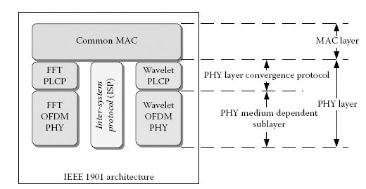
FIGURE 13.1
IEEE 1901 functional layers.
The PLCP defines methods for mapping MAC protocol data units (MPDUs) into a framing format that is suitable for the associated PMD system. This is an intermediate layer that helps translate data from the common MAC into two different PMD systems (FFT and wavelet).
The system architecture and the protocol entities of an IEEE 1901 FFT-OFDM station and how they relate to each other are described in Figure 13.2. The descriptions of the different protocol entities are as follows:
• The PHY layer is responsible for the PHY layer signal format such as the symbol generation, modulation and forward error correction (FEC).
• The MAC layer is responsible for the channel AC control and the data plane.
• The convergence layer provides support functions to the MAC such as bridging, packet classification, auto-connect and jitter control.
• The connection manager is used to set up connections to provide QoS for certain streams.
• The basic service set (BSS) manager (BM) is responsible for the set-up and maintenance of the network (a 1901 FFT-OFDM network is termed a BSS, see Section 13.4), managing the communication resource on the wire and coordinating with neighbouring BMs.
The higher layer entity (HLE) corresponds to all the layers responsible for generating traffic (both data and control messages) to be transmitted using the IEEE 1901 FFT-OFDM device. The HLE communicates the data and the control information (required to configure the station/BSS) using the service access points (SAPs).

FIGURE 13.2
System architecture of a 1901 FFT-OFDM station.
In this section, a brief summary of the FFT-PHY is provided. The power line channel and noise have a few distinct characteristics (see Chapters 4 and 5):
• It is highly frequency selective with the average attenuation generally increasing with frequency.
• It suffers from narrowband interference due to ingress from existing radio services, wireless products and unintentional interference from devices like microwaves.
• There is substantial impulse noise on the power line generated by electrical loads from such items as halogen lamps and devices utilising motors (e.g. hair dryers).
OFDM [2,3] is a modulation technique that easily adapts to frequency-selective channels. Different carriers carry different amounts of information based on signal-to-noise ratio (SNR). OFDM is also inherently resilient to narrowband interference (only a few carriers are affected) and is robust in the presence of impulse noise. It also has a very efficient implementation using an inverse fast Fourier transform (IFFT).
The FFT-PHY uses 1974 carriers between 1.8 and 50 MHz with a carrier spacing of approximately 24.414 kHz. The use of frequencies greater than 30 MHz is optional. Certain frequency bands between 1.8 and 30 MHz are used for amateur (HAM) radio broadcasts. Various regulatory bodies – as described in Chapter 6 – in different parts of the world have imposed limits on intentional and unintentional transmit power in these bands to avoid interference to the radio services. Typically, the power, for example, in the HAM bands, should be 30 dB lower than the maximum transmit power allowed in the 1.8–50 MHz band. IEEE 1901 FFT-OFDM employs time domain pulse shaping of the OFDM symbols that enables achieving deep frequency notches without requiring explicit transmit notch filters. By just turning off carriers in the HAM bands and creating a 100 kHz guard band on either side of the HAM band, 30 dB notches are easily achieved. Turning off carriers to meet the notch requirements leaves 917 active carriers that can be used for data transmission in the 1.8–30 MHz band.
The carriers used for data transmission may be coherently modulated with a binary phase-shift keying (BPSK), a quadrature phase-shift keying (QPSK) and six different quadrature amplitude modulation (QAM) modes: 8-QAM, 16-QAM, 64-QAM, 256-QAM, 1024-QAM and 4096-QAM. Support for 4096-QAM is optional. The FFT-PHY uses a turbo code [4,5,6,7] for FEC. The turbo code provides good coding gain at low SNRs and hence optimises performance on poor power line channels. For additional robustness required for critical management messages and broadcast messages, IEEE 1901 FFT-OFDM also provides three additional signalling schemes called robust OFDM (ROBO), mini ROBO (MINI-ROBO) and high-speed ROBO (HS-ROBO). Additional details on modulation and coding are provided in Section 13.3.
W-OFDM [8,9] has two main features that enable the achievement of a better spectral efficiency than the FFT-based OFDM system described in Section 13.2.1: lower side lobes and lack of guard intervals (GIs).
Lower side lobes can be attributed to the use of filters that span multiple symbol durations in W-OFDM when compared to the single symbol duration pulse-shaping filter in FFT-OFDM. Having low side lobes has two advantages: it does not require turning off additional carriers on either side of a HAM band to achieve deep spectral notches, and it also increases robustness to narrowband interference.
In FFT-OFDM, symbols do not overlap, and thus a GI is introduced to combat any symbol overlap or inter-symbol interference (ISI) introduced by the channel. In W-OFDM, consecutive symbols overlap in time by design (IEEE 1901 W-OFDM has an overlap factor of four symbols). Thus, a GI is not required to avoid symbol overlap. Although this does not eliminate ISI completely, it does lead to lower overhead in W-OFDM.
The IEEE 1901 W-OFDM PHY defines transmitting a W-OFDM frame in two different ways: (1) directly at baseband or (2) by modulating to a band-pass carrier. It is mandatory to support baseband transmission for IH and AC applications. Band-pass is an optional feature.
For baseband transmission, the IEEE 1901 W-OFDM PHY has 512 uniformly spaced carriers between DC (0 MHz) and 31.25 MHz. Only carriers between 1.8 and 28 MHz are used for data transmission. After accounting for HAM band notches, there are 312 active carriers remaining for data transmission. The carriers are modulated with five different pulse-amplitude modulation (PAM) modes: 2-PAM, 4-PAM, 8-PAM, 16-PAM and 32-PAM (optional). The mode where each tone carries independent data is called the high-speed mode. For more robust transmissions, IEEE 1901 W-OFDM also specifies a diversity mode where additional frequency domain copies are provided. Two types of FEC are specified: a mandatory concatenated code using Reed–Solomon and convolutional codes and an optional low-density parity check (LDPC) code.
The IEEE 1901 W-OFDM PHY defines 1024 evenly spaced carriers into any bands lying in the 1.8–50 MHz range for the optional band-pass transmission. Apart from allowing varying bands with a constant number of carriers, baseband transmission has the same coding, modulation and diversity definitions as in baseband transmission.
The IEEE 1901 W-OFDM PHY has a PHY protocol data unit (PPDU) that contains the following fields:
• W-OFDM PPDU preamble that contains 11–17 W-OFDM symbols
• Tone map index (TMI) field with one W-OFDM symbol that contains tone map (TM) information used in generating the frame body
• Frame length (FL) field with one W-OFDM symbol to indicate the frame body length
• Frame control (FC) field with more control information on the PPDU
• Frame body with variable data and tail bits to bring the encoding to a known state
• Pad bits
The TMI and FL fields are passed through a rate 1/2 convolutional code. The FC field is encoded with Reed–Solomon and convolutional concatenation. The frame body is first scrambled and then encoded with RS and convolutional concatenation or LDPC coding. After encoding, the TMI, FL, FC and frame body fields are passed through bit interleaving. Finally, interleaved bits for these fields are diversity copied and mapped to OFDM carriers. All the fields are then transmitted with base-band or band-pass W-OFDM transmission.
13.3 1901 FFT-PHY: A Functional Description
A block diagram of the different functional blocks that comprise an IEEE 1901 FFT-PHY transmitter is shown in Figure 13.3. Conceptually, the FFT-PHY transmitter can be thought of as three independent processing chains, although certain blocks may be shared between these chains to reduce implementation complexity:
• A preamble generator chain: Responsible for generating the IEEE 1901 FFT-OFDM preamble that provides packet synchronisation functionality.
• An IEEE 1901 FFT-OFDM FC encoder chain: Responsible for generating the IEEE 1901 FFT-OFDM FC symbol that is present in every PPDU transmission. The FC symbol carries addressing information and other information required to demodulate and decode the packet. Decoding of the FC is critical for successful decoding of the payload in a PPDU. If the FC decoding fails, then no information in the payload portion of the PPDU can be recovered.
• An IEEE 1901 FFT-OFDM payload encoder: Responsible for generating the payload portion of the PPDU.
The IEEE 1901 FFT-OFDM FC encoder and payload encoder receive MAC segments that are processed by the PLCP layer. The smallest unit that is processed by the FFT-PHY is referred to as a PHY block (PB). A PB header (PBH) is added to the MAC segment, and a PB checksum (PBCS) that is computed over the PBH and the body of the PB is appended to the end. Two different-length cyclic redundancy checks (CRCs), CRC-32 and CRC-24, are specified to compute the PBCS. The segmentation procedure is shown in Figure 13.11. The preamble generator does not need any input from the MAC; the only input it requires is a reference phase table that is specified in the IEEE 1901 standard that is typically stored in read-only memory (ROM).
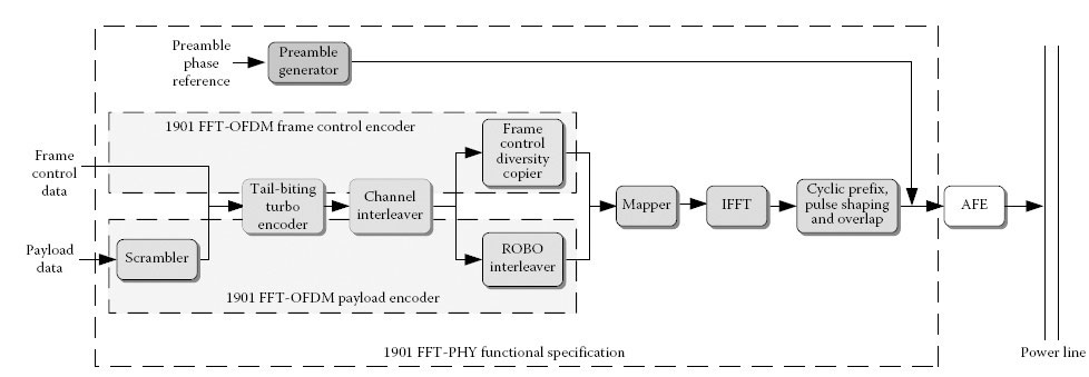
FIGURE 13.3
IEEE 1901 FFT transmitter. (Reprinted from IEEE Std 1901–2010: IEEE standard for broadband over power line networks: Medium access control and physical layer specifications, IEEE Standards Association, 2010. Available online http://standards.ieee.org/store. Copyright © 2010 IEEE. All rights reserved. With permission.)

FIGURE 13.4
1901 FFT-OFDM PPDU. The numbers at the bottom indicate the number of samples for each portion of the PPDU (assumes a 100 MHz clock). (Reprinted from IEEE Std 1901–2010: IEEE standard for broadband over power line networks: Medium access control and physical layer specifications, IEEE Standards Association, 2010. Available online http://standards.ieee.org/store. Copyright © 2010 IEEE. All rights reserved. With permission.)
As shown in Figure 13.3, blocks like the turbo encoder and channel interleaver are shared between the 1901 FFT-OFDM FC encoder and payload encoder. The scrambler and ROBO interleaver blocks are only used by the payload encoder and are not used to generate the FC. The frequency domain FC data are obtained by passing the FC information from the MAC and PLCP through a turbo encoder and a FC diversity copier – which introduces some frequency diversity by repeating the FC bits on different carriers. The frequency domain payload data are obtained by passing payload PBs first through a scrambler, then a turbo encoder and finally a channel interleaver. For payloads transmitted using ROBO modes, the interleaver also introduces frequency and time domain redundancy. The frequency domain bits, irrespective of whether they are FC or data bits, pass through a common OFDM modulation chain consisting of a mapper, IFFT and a symbol shaping with overlap block. The mapper is responsible for converting the bitstream into modulation symbols. Each carrier can transport a different modulation. The vector specifying the mapping of modulation modes to carriers is referred to as a TM. The TM is estimated at the receiver and fed back to the transmitter. The mapper uses the TM to determine how many bits to put on each carrier. The IFFT is responsible for OFDM modulation and converts the frequency domain data into a time domain OFDM symbol. Then a cyclic prefix [2] is appended to the OFDM symbol before a pulse shaping is applied to the composite signal. The shaped signals are then overlapped with adjacent shaped symbols. These overlapped symbols are fed into the analog front end (AFE). The AFE module is not specified in the IEEE 1901 FFT-OFDM standard and is implementation dependent. However, the standard does specify the maximum level and fidelity of the signals at the output of the AFE.
The PHY entity comprising a concatenation of the preamble, FC and a sequence of pay-load symbols is referred to as the PPDU and is shown in Figure 13.4. Depending on the type of PPDU being transmitted, the payload portion may or may not be present. For instance, the selective acknowledgment (SACK) is conveyed as a PPDU with only a preamble and a FC.
13.3.1 IEEE 1901 FFT-OFDM Preamble Generator
The preamble provides the receiver with a reference symbol for packet synchronisation. The preamble signal is chosen to have good autocorrelation properties and is typically much more robust than the packet body (a preamble can be detected even under very low SNR conditions where payload communication is not possible). As shown in Figure 13.4, the preamble consists of a sequence of ‘plus’ and ‘minus’ short OFDM symbols that are repeated. The ‘plus’ symbol is called the SYNCP symbol and is generated by modulating as set of reference phases onto carriers between 1.8 and 30 MHz that are spaced approximately 195.3125 kHz apart. A windowing is applied on the symbol, and the symbols are overlapped during concatenation. The ‘minus’ or SYNCM symbols are obtained as a negation of the SYNCP symbol. The preamble consists of seven and a half SYNCP symbols (starting with the first half of the SYNCP followed by seven SYNCP symbols) and two and a half SYNCM symbols (starting with two SYNCM symbols and ending with the first half of a SYNCM symbol).
At the receiver, a correlation is performed of the received signal against a SYNCP signal. The presence of multiple SYNCP symbols can be used to improve detection performance by combining the outputs of consecutive correlation operations. When the correlator fires, there may still be an ambiguity as to which SYNCP symbol is detected. Then the receiver can search for the transition between the SYNCP and SYNCM symbols to find out exactly where on the packet the correlator fired and where the packet boundaries are.
The scrambler is only applicable to the payload portion of the PPDU. The FC bits are not scrambled. It is possible that the bits obtained from the MAC and PLCP are correlated. The scrambler helps to randomise the input sequence to the turbo encoder. The scrambler is implemented as a simple shift register module operating on the input bits. The generator polynomial for the scrambler is given by polynomial S(x) = x10 + x3 + 1. The operation of the scrambler is shown in Figure 13.5.
13.3.3 IEEE 1901 FFT-OFDM Turbo Encoder
IEEE 1901 FFT-OFDM specifies a turbo code that is a parallel concatenation of two duobinary tail-biting convolutional codes, as shown in Figure 13.6. The turbo code consists of two identical constituent recursive systematic convolutional (RSC) codes that are separated by an interleaver. The turbo interleaver is an algorithmic interleaver that is specified by a single equation and is parameterised by a seed table and two variables. Depending on the input block size to the decoder, a particular seed table and values for the other two parameters are specified and uniquely determine the interleaver table. Details of the interleaver can be found in the IEEE 1901 standard [10].
The constituent RSC code is shown in Figure 13.7. It is a rate 2/3 code producing one parity bit for every two information bits. Thus, the code rate of the turbo code is rate 1/2 before puncturing (for every two information bits, each RSC code produces one parity, and the output of the turbo code is the two information bits + two parity bits leading to code rate of 2/4). Each constituent code is easily implemented using the eight-state linear feedback shift register structure that is shown in Figure 13.7.
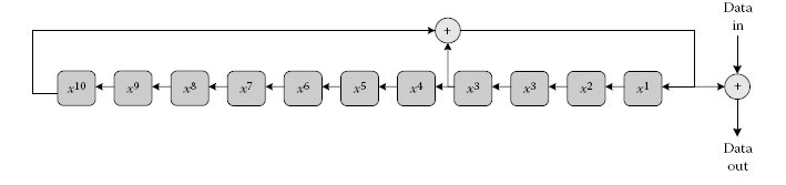
FIGURE 13.5
IEEE 1901 FFT-OFDM data scrambler. (Reprinted from IEEE Std 1901–2010: IEEE standard for broadband over power line networks: Medium access control and physical layer specifications, IEEE Standards Association, 2010. Available online http://standards.ieee.org/store. Copyright © 2010 IEEE. All rights reserved. With permission.)

FIGURE 13.6
IEEE 1901 FFT-OFDM turbo code. (Reprinted from IEEE Std 1901–2010: IEEE standard for broadband over power line networks: Medium access control and physical layer specifications, IEEE Standards Association, 2010. Available online http://standards.ieee.org/store. Copyright © 2010 IEEE. All rights reserved. With permission.)
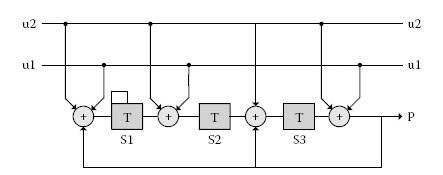
FIGURE 13.7
Constituent RSC code. (Reprinted from IEEE Std 1901–2010: IEEE standard for broadband over power line networks: Medium access control and physical layer specifications, IEEE Standards Association, 2010. Available online http://standards.ieee.org/store. Copyright © 2010 IEEE. All rights reserved. With permission.)
For efficient decoding of turbo codes, the ending state of the RSC has to be known. This is achieved in conventional turbo codes by feeding in additional termination bits to force the end state of the shift register to a known value. The extra bits constitute a rate loss. This is avoided by using a tail-biting RSC. Tail-biting encoding (see [11,12,13,14] and references therein) is an encoding approach that ensures that the starting and ending states of the RSC are the same. Tail biting typically requires a two-pass encoding approach. The shift register is initialised to the all-zero state, and the information bits are run through the encoder. Depending on the ending state of the shift register, a look-up table (LUT) provides a new starting state. The shift register is then initialised to the new starting state, and then another round of encoding with the same information bits is performed. The ending state after the second round of encoding is the same as the new starting state specified by the LUT. The fundamentals behind the approach to generating the new starting state LUT are given in [12]. The IEEE 1901 FFT-OFDM standard [10] specifies the starting state LUT for the turbo code presented in this section.
Turbo codes with duo-binary RSC constituent codes have been well studied in the open literature [11–14] and have many other advantages in addition to not requiring termination bits. Some of them include the following:
• Less sensitive to puncturing: Unlike conventional turbo codes, tail-biting turbo codes can tolerate higher levels of puncturing. In fact, IEEE 1901 FFT-OFDM has a default operating code rate of 16/21.
• Larger minimum distance: This affects the error performance of the turbo code at low SNRs. The power line channel is a pretty adverse medium, and typically, the operating region for packet error rates lays around 10−2. Having a larger minimum distance improves the performance on low-SNR, high-BLER region.
• Duo-binary turbo codes usually have an error floor that is multiple orders of magnitude lower than binary turbo codes [11]. The power line channel is also a very noisy medium, and in the typical operating range of frame error rates (10−1−10−3), the HPAV turbo code can be considered nearly error-floor free.
• Better convergence properties of iterative decoding.
• Lower latency: For each clock cycle, the encoder/decoder outputs two bits instead of one (such as in a conventional binary turbo code), leading to lower latency.
Code rates and block sizes that are supported in IEEE 1901 FFT-OFDM are summarised in Table 13.1.
13.3.4 Frame Control Diversity Copier
As seen in Table 13.1, the FC is a 16-byte (128-bit) PB that is encoded at a code rate of 1/2 to produce 256 output bits. These bits are then interleaved by the channel interleaver. Since the bits are already interleaved, the only purpose of the FC diversity copier is to maximally spread copies of the bits amongst all the available (not notched) carriers. FC information is conveyed using QPSK, and hence the encoded bits are repeated on both the in-phase (I) and quadrature (Q) components of certain carriers. Assuming that the interleaved bits indexed from 0 to 255, then interleaved bits are copied to I and Q components with an offset of 128 between the Q and I channels, as shown in Table 13.2.
The channel interleaver randomises the location of the information and parity bits to protect against burst errors. The IEEE 1901 FFT-OFDM channel interleaver is essentially a rectangular interleaver. The bits are written sequentially in columns, and then the interleaved output is read out in rows. The information bits and parity bits are interleaved separately and then interlaced together. The information (or parity) bits are written sequentially into the columns of an N × 4 interleaver table, where N depends on the block size and code rate being used. All the block size and code rate combinations produce encoded bits in multiples of four, and hence the interleaver table is always fully populated. The information bits are read out starting at Row 0 and then progress incrementally to the next row that is a specific step-size away, and so forth. When the last row is reached, the process is repeated starting at Row 1, and this continues until all the information bits are read out. The process for the parity bits is exactly the same, but instead of starting at Row 0, the process is initiated at a row that is at a specific amount offset from Row 0. The two sets of interleaved information bits and interleaved parity bits are interlaced as specified in the IEEE 1901 FFT-OFDM standard [10] to arrive at the interleaved output. The parameters for the rectangular interleaving of information and parity bits are summarised in Table 13.3.
Block Size and Code Rate Support in the IEEE 1901 FFT-OFDM
PB Type |
PB Size (Octets) |
Code Rate |
FC |
16 |
1/2 |
Payload |
136 |
16/21, 8/9 (optional) |
520 |
16/21, 8/9 (optional) |
Bit Addressing for the FC Diversity Copier
Used Carrier # |
Encoded Bit Index Carrier on the I-Channel |
Encoded Bit Index Carrier on the Q-Channel |
0 |
0 |
128 |
1 |
1 |
129 |
… |
… |
… |
i |
i mod 256 |
(i+128)mod 256 |
… |
Source: Reprinted from IEEE Std 1901–2010: IEEE standard for broadband over power line networks: MAC control and PHY layer specifications, IEEE Standards Association, 2010. Available online http://standards.ieee.org/store. Copyright © 2010 IEEE. All rights reserved. With permission.
In addition to the rectangular interleaving, the bits that are read out from each row are interleaved amongst each other to further randomise the output stream. For more details on this process, called sub-bank switching, the interested reader may refer to the actual standard document [10].
Channel Interleaver Parameters
PB Size (Octets) |
Code Rate |
Step Size |
Row Offset (for Parity Bits) |
16 |
1/2 |
4 |
16 |
136 |
1/2 |
16 |
136 |
16/21 |
8 |
40 |
|
8/9 |
11 |
16 |
|
520 |
1/2 |
16 |
520 |
16/21 |
16 |
170 |
|
8/9 |
11 |
60 |
Source: Reprinted from IEEE Std 1901–2010: IEEE standard for broadband over power line networks: MAC control and PHY layer specifications, IEEE Standards Association, 2010 Available online standards ieee org/store. Copyright © 2010 IEEE All rights reserved With permission.
IEEE 1901 FFT-OFDM uses ROBO modes for various purposes such as session set-up, broadcast and multicast communication, beacon transmissions and exchange of management messages. Three different ROBO modes, namely, ROBO, HS-ROBO and MINI-ROBO, are specified.
All ROBO modes use rate 1/2 FEC and QPSK modulation. A single PB is first encoded and interleaved. Then, the ROBO interleaver operates on the output of the channel interleaver. The ROBO interleaver introduces frequency and time diversity by repeating the interleaver output on different carriers and different OFDM symbols, respectively. The number of copies depends on the type of ROBO mode. The ROBO interleaver creates the required redundancy by reading the output of the channel interleaver multiple times with different cyclic shifts. The different ROBO modulations, the corresponding PB sizes and redundancy factors are specified in Table 13.4. Note that the data rate depends on the number of used carriers in the 1.8–30 MHz band. For the default 917 used carriers that remain after all the HAM bands are notched, the data rates are 3.8, 4.9 and 9.8 Mbps for MINI-ROBO, ROBO and HS-ROBO, respectively. It is seen that MINI-ROBO has the lowest PHY rate and most robustness (number of copies). Therefore, this is typically used for transmissions that are critical to maintaining a network. For instance, beacons are transmitted using MINI-ROBO. Details of the ROBO interleaving algorithm can be found in the IEEE 1901 standard [10].
The mapper is responsible for converting the input bitstream into constellation symbols for each carrier. The operation of the mapper can be summarised as follows:
• FC symbol: Pairs of bits are mapped using QPSK onto the used carriers.
• ROBO, HS-ROBO and MINI-ROBO: Pairs of bits are mapped using QPSK onto the used carriers.
• Payload symbols: The number of bits on each carrier depends on the TM. Based on the TM, an appropriate number of bits are mapped using BPSK, QPSK, 8-QAM, 16-QAM, 64-QAM, 256-QAM, 1024-QAM or 4096-QAM onto each of the used carriers.
If the TM indicates that a particular carrier has zero bits allocated to it, then the mapper uses a pseudo-noise (PN) generator with the polynomial S(x) = x10 + x3 to generate a random bit that is modulated using BPSK. It then assigns the bit to that carrier. This is to aid in estimating the SNR on that carrier in case the SNR eventually improves enough to support any of the supported modulation levels, which would allow the carrier to be used for transmitting payload data. The bits in the generated PN sequence are initialised to all 1s at the start of the first OFDM payload symbol. When a used (not notched) carrier is assigned 0 bits, the existing value in the first register (x1) is used for BPSK modulation, and then the PN sequence generator is advanced.
IEEE 1901 FFT-OFDM ROBO Mode Parameters
ROBO Mode |
PB Size (Octets) |
Number of Copies |
MINI-ROBO |
136 |
5 |
ROBO |
520 |
4 |
HS-ROBO |
520 |
2 |
Source: Reprinted from IEEE Std 1901–2010: IEEE standard for broadband over power line networks: MAC control and PHY layer specifications, IEEE Standards Association, 2010. Available online http://standards.ieee.org/store. Copyright © 2010 IEEE All rights reserved. With permission.
In addition to modulating each carrier with a constellation symbol, the mapper also rotates the constellation on each carrier by a reference phase. The phase reference vector specified in IEEE 1901 FFT-OFDM was chosen to maintain a certain peak-to-average ratio. The mapper finally scales the constellation symbol to maintain unity average power for each modulation level.
13.3.8 Symbol Generation (Cyclic Prefix, Pulse Shaping and Overlap)
This block is responsible for generating the sequence of OFDM symbols in a PPDU for transmission over the power line. We will assume a sampling frequency of 100 MHz in the section. The functionality of this block is to generate a windowed OFDM symbol, as shown in Figure 14.12. The operation of this block can be broken into the following steps:
1. Add a cyclic prefix to the OFDM symbol obtained at the output of the IFFT. The duration of the OFDM symbol at the output of the IFFT is T = 40.96 μs (4096 samples). The duration of the cyclic prefix, tprefix, is split into a roll-off interval (RI) that is used for windowing/pulse shaping and a GI that is used for combating ISI. The duration of the cyclic prefix depends on the GI used. The RI spans 4.96 μs. Three mandatory GIs of 5.56, 7.56 and 47.12 μs are specified. Apart from these, eight other optional GIs are also supported. The extended OFDM symbol with the cyclic prefix spans a duration of TE = T + tprefix.
2. Apply the pulse-shaping window specified in the IEEE 1901 FFT-OFDM standard [10] over the first RI and last RI symbol of the extended OFDM symbol obtained earlier. The pulse shaping helps to achieve the 30 dB notch depth required in the HAM bands.
3. Overlap the first RI/2 samples of the current windowed symbol with the last RI/2 samples of the previous windowed symbol. This results in an OFDM symbol duration of TS = T + GI = 40.96 μs + GI.
The sequence of overlapped symbols is then sent to the AFE and transmitted on the power line.
13.4 IEEE 1901 In-Home MAC: Functional Overview
IEEE 1901 IH networks are designed to support audio/video streaming applications within the home. This section gives an overview of the 1901 MAC. Both the 1901 FFT-OFDM and the 1901 W-OFDM systems support similar MAC functionalities. However, the details of each of these functionalities are different. This section discusses the details of the different MAC functionalities as applicable to the 1901 FFT-OFDM systems. A brief description of an IEEE 1901 network is provided initially along with the protocol entities in a 1901 station. This is followed by details of the formation of the network, channel AC mechanisms, channel estimation to utilise the medium effectively, the MAC data plane and the different MAC packet transmission mechanisms.

FIGURE 13.8
Network topology and components. (Reprinted from IEEE Std 1901–2010: IEEE standard for broadband over power line networks: Medium access control and physical layer specifications, IEEE Standards Association, 2010. Available online http://standards.ieee.org/store. Copyright © 2010 IEEE. All rights reserved. With permission.)
A 1901 network (also termed a BSS) consists of a set of member stations that can communicate with one another exclusively. Each BSS is a centrally managed network, managed by a station called the BM. The BM is responsible for the creation, maintenance and operation of a BSS. A BM controls the channel AC in the BSS. The BM periodically transmits a beacon which contains essential information for the functioning of the BSS such as the list of stations in the network and channel AC schedule information.
Figure 13.8 describes an example of two neighbouring BSSs. BSS1 consists of a BM, a proxy BM (PBM) and two stations, while BSS2 consists of a BM and three stations. The two BSSs are neighbouring, and the BMs of the two BSSs can coordinate with each other with respect to sharing resources and channel AC. In the case of BSS1, station STA2 is hidden from its BM. In such circumstances, one of the stations can take on the role of a PBM to provide the BM functionalities to STA2.
A BSS is a set of stations with the same network membership key (NMK). A NMK is a 128-bit advanced encryption standard (AES) key. Stations with the same NMK automatically form a BSS. It is up to the user to provide the NMK to all of the stations intended to be a part of the BSS. The provisioning of this NMK to each of the stations in the BSS is termed authorisation. There are multiple ways in which a NMK can be provided to various stations in a BSS:
• Direct entry: NMK provisioning using this technique requires an available user interface on each station. A user can enter the NMK using this interface on each station. An alternative, user-friendly technique is entering a network password (NPW) on each station. This NPW can be hashed to produce the NMK.
• Remote entry: This requires a user interface on a remote station. The user enters the device password (DPW) or a device access key (DAK) of a new station to this remote station. The remote station can send the NMK to the new station encrypting it using the DAK. The DPW is a user-friendly alternative to the DAK that can be derived by hashing the DPW.
• Simple connect: This is a user-friendly way of forming a BSS. This technique involves pushing buttons on the two devices within a very short time span either to form a network or to add a new station into the network. When the buttons are pushed, temporary encryption keys are exchanged between the two nodes using unicast control messages. These temporary encryption keys are used to exchange the NMK.
The direct entry and remote entry methods of authorisation provide the highest security but require a fairly sophisticated user interface. The simple connect method of authorisation is very user-friendly and requires a simple user interface. However, this technique is less secure.
Any of the stations in the BSS can become the BM. When a network is formed, one of the stations must become the BM. The selection methods for determining the BM station are as follows:
• User-appointed BM: The user can appoint a particular station to be made the BM. Care should be taken by the user to only appoint one station as the BM in a BSS.
• BM bandwidth management capability: Each station has different bandwidth management capabilities (carrier sense multiple access [CSMA] only, uncoordinated mode or coordinated mode) if functioning as a BM. A station that can operate a BSS in the coordinated mode has the highest preference of becoming a BM. Details of the different modes of operation are described in Section 13.2.
• BM based on topology: A station can become a BM depending on the topology of the BSS. A station with the best connection to every other station in the network is the best candidate for becoming a BM.
The BM is responsible for maintaining the function of a BSS. When another station becomes more capable than the existing BM in a BSS, then the BM functionality can be handed over to the other station. This can be done in a seamless fashion, without disturbing the operation of the BSS. Another station in the BSS will always be appointed as a backup BM to enable recovery in the event of a BM failure. The backup BM will maintain the information required to manage the BSS, so that recovery is seamless.
Once a BM is appointed in the BSS, the BM initiates the association process. To accomplish this, the BM provides an 8-bit terminal equipment identifier (TEI) for every station in the BSS including itself. Every transmission on the power line has a FC associated with it. This TEI is used for addressing in all FCs instead of the 6-octet MAC address associated with the station. The TEI has a finite amount of lease time. It is up to the station to renew the lease time.
An IEEE 1901 network is a secure network. The BM generates a random key called the network encryption key (NEK). This key is distributed to all the stations in the BSS using the NMK, thereby authenticating the stations in the BSS. All the transmissions in the network except for a select few control messages (e.g. messages required for joining/forming a new BSS or communications between nodes belonging to different BSSs) are encrypted using this NEK. To maintain a high level of security, the NEK is periodically updated and provided to all the stations using the NMK.
The BM maintains a list of valid TEIs in the BSS and updates every station with the latest list of valid TEIs regularly. A BM can remove a station from the BSS by providing a new NMK to every station in the network except for the station that needs to be removed.
13.4.2 Channel Access Mechanisms
IEEE 1901 FFT-OFDM supports both time division multiple access (TDMA) and CSMA. The BM determines the mode of channel AC and also the duration of time for which each AC method is valid. The time is divided into beacon cycles. Each beacon cycle is two AC line cycles long (33.33 ms where the AC line cycle frequency is 60 Hz and 40 ms where the AC line cycle frequency is 50 Hz). Each BSS can operate in any of the following three modes:
1. CSMA-only mode: In this mode of operation, the entire beacon cycle is available for CSMA channel AC only. All of the transmissions including the beacon transmissions use CSMA channel AC.
2. Uncoordinated mode: This mode of operation is present in the case of single BSS scenarios. In this mode of operation, the beacon cycle is divided into at least two regions: beacon region (reserved for transmissions of beacons) and persistent CSMA region (reserved for CSMA AC to be shared by all the nodes in the network). The remaining cycle is split into multiple TDMA regions and nonpersistent CSMA regions.
3. Coordinated mode: This mode of operation is present whenever multiple BSSs exist and TDMA channel AC is required. The beacon cycle in each of the BSSs has a beacon region, a shared CSMA region (which is common for all the networks), a stay-out region (wherein all the stations belonging to the BSS will restrain from transmissions) and a reserved region (which consists of all the TDMA allocations and nonpersistent CSMA allocations). The BMs of the neighbouring BSSs coordinate with each other to carve out their individual stay-out regions. A reserved region in one BSS may align with the stay-out regions of other BSSs. The beacon period will have multiple beacon slots with one slot reserved for the transmission of beacons of a particular coordinating BSS.
The CSMA channel AC mechanism used in IEEE 1901 FFT-OFDM networks is a prioritised channel AC. Each channel AC during CSMA consists of a priority resolution period, followed by the random back-off contention period, which is then followed by actual transmission.
Figure 13.9 describes a CSMA/CA channel AC followed by a packet transmission (this is described in detail in Section 13.4.5). When a station is ready to transmit, signalling is done in the two priority slots. Depending on the priority of the intended transmission, a station either transmits a priority resolution signal (PRS) or listens in a priority slot. A station loses its priority contention if it detects a PRS in one of the priority slots. Table 13.5 describes the different types of priority signalling (with MA3 the highest and MA0 the lowest priority) for different MAC priorities. Start of frame (SOF), SACK, response interframe space (RIFS) and CIFS are detailed when introducing Figure 13.12.

FIGURE 13.9
CSMA/CA channel AC. (Reprinted from IEEE Std 1901–2010: IEEE standard for broadband over power line networks: Medium access control and physical layer specifications, IEEE Standards Association, 2O1O. Available online http://standards.ieee.org/store. Copyright © 2010 IEEE. All rights reserved. With permission.)
Priority Signalling for Different MAC Priorities
MAC Priority |
PRS Signal in PRS 0 |
PRS Signal in PRS1 |
MA3 |
Transmit |
Transmit |
MA2 |
Transmit |
Listen |
MA1 |
Listen |
Transmit |
MA0 |
Listen |
Listen |
Source: Reprinted from IEEE Std 1901–2010: IEEE standard for broadband over power line networks: MAC control and PHY layer specifications, IEEE Standards Association, 2010. Available online http://standards.ieee.org/store. Copyright © 2010 IEEE. All rights reserved. With permissio.
The priority with which a packet transmission occurs depends on the payload of the transmissions. A user can assign a priority to different types of traffic using the QoS field in the VLAN tag [15]. This can be mapped into one of the four MA priorities as described in subclause 7.7.3 of IEEE 802.1D [16]. Beacons, which are essential for the functioning of the BSS, can be transmitted using MA3.
IEEE 1901 FFT-OFDM stations use a modified exponential back-off procedure during CSMA. Each station maintains a backoff procedure event counter (BPC) for each priority level. When a station is ready to transmit, it backs off for a random number of contention slots, each slot being 35.84 μs long. The maximum contention window depends on the BPC. The BPC depends on priority of transmission, the number of successive collisions and the number of times the station had to defer to transmissions of the same priority. The dependence on the number of times transmissions had to defer is to further reduce the collision probability. Upon gaining priority AC to the channel, the station performs a random backoff. If no other transmissions are detected during the back-off, the station proceeds with the transmission. Otherwise, it increments its defer counter. If the transmission results in a collision or if the defer counter reaches a limit corresponding to the current BPC, its BPC counter is incremented. The defer counter is reset to zero each time the BPC is incremented or upon a transmission. The successive collision counter and the BPC are reset to zero upon a successful transmission. Table 13.6 provides the details of the different counters used for the priority back-off for MA0 and MA1.
Max Contention Window as a Function of Defer Counter and Successive Collisions
BPC |
Successive Collisions |
Defer Counter |
Contention Window (# of Contention Slots) |
0 |
0 |
0 |
7 |
1 |
1 |
1 |
15 |
2 |
2 |
3 |
31 |
> = 3 |
> = 3 |
15 |
63 |
During TDMA channel AC, the AC to the power line medium is reserved specifically for a source destination node pair. During this reserved period, the source controls the entire AC to the channel. The different kinds of MPDU transmissions as described in Section 13.4.5 are all permitted during a TDMA channel AC. It is important to note that all transmissions between the node pair will be restricted to the time allocated for this pair.
The power line has many appliances and devices connected on it. This results in impedance mismatches. The signals transmitted on this channel get reflected multiple times, resulting in multipath delay spread at the receiver. There is significant non-AWGN noise introduced to the channel by these appliances and devices. The noise introduced on this channel varies as a function of the AC line cycle. This phenomenon is also valid for lower frequencies and shown in detail in Chapter 2. Additionally, there is a long-term variation of the channel characteristics resulting from the various appliances powering on and off. The IEEE 1901 FFT-OFDM channel estimation is designed to handle these dynamic properties of the power line channel. The stations also operate in two different bands: 1.8–30 MHz and 1.8–50 MHz.
As a part of the channel estimation process, the transmitter and the receiver determine the common band of operation, a set of tonemaps and the different portions of AC line cycle during which each of the tonemaps can be used. A tonemap corresponds to a unique combination of modulation per carrier, FEC code rate to be used and the GI length to be used.
IEEE 1901 FFT-OFDM has a predefined set of tonemaps called the ROBO tonemaps. These tonemaps are designed to be robust enough to handle the harshest channel conditions and are therefore not efficient for data transmissions. They range in data rate from 5 to 10 Mbps. When a station has data to transmit and does not possess any user-defined tonemaps, it initiates the channel estimation process. As a part of this process, the station transmits a special MPDU (sound MPDU) to the receiver. When the receiver has collected a sufficient number of sound MPDUs, it generates a default tonemap along with AC line cycle region-specific tonemaps. The default tonemap can be used in any part of the AC line cycle. Once the transmitter receives the set of tonemaps, it will start transmitting data packets using these tonemaps. To handle dynamic channel changes, the receiver continues to monitor the channel and continuously updates the transmitter with new sets of tonemaps. As previously mentioned, the power line channel characteristics are different for different portions of the line cycle. Figure 13.10 describes an example with an AC line cycle divided into four tonemap regions and the different tonemaps (T1, T2, T3 and T4) associated with each region. Transmissions using a particular tonemap have to be restricted to the region where the tonemap is valid. They cannot span multiple regions.

FIGURE 13.10
Tonemap regions w.r. t. AC line cycle and beacon cycle.
The IEEE 1901 system supports the transmission of Ethernet packets. It limits the type of data that can be transmitted between stations that are not associated or authenticated to a subset of management messages. Data exchange between such stations is strictly prohibited. Any Ethernet packet received from the data SAP is called a MAC service data unit (MSDU), and the MAC sub-layer transports these MSDUs to the intended receiver.
Each transmitter maintains several queues as described here:
1. Unicast queues for each receiver
a. Four priority queues for data
b. One queue for management/control frames
2. Broadcast queues
a. Four priority queues for data
b. One queue for management/control frames
3. Specific queues for established connections
Any incoming MSDU belongs to an established connection or is independent. These MSDUs are classified upon arrival based on the destination address, the connection type and whether it is a management frame or a data frame. Connection-oriented MSDUs are passed on to the specific queue corresponding to that connection. The independent data MSDUs are passed on to one of the priority queues maintained for the specific receiver. The user-defined priority of the MSDU is mapped to a particular channel AC priority as specified by IEEE 802.1D [17].
The flow of data through an IEEE 1901 FFT-OFDM station is shown in Figure 13.11. Each arriving MSDU is prepended with a MAC frame header and appended with an integrity check vector (ICV) to form a MAC frame. The ICV is used to verify that the MAC frame is received correctly. The arriving MSDUs have the original source address (OSA), the MAC address from where the MAC frame originated, the original destination address (ODA) (the MAC address where the particular MAC frame is eventually intended to be consumed) and an Ethertype. The MAC frame header is a two-octet field that carries information about the validity of the MAC frame, the presence of an arrival time stamp (ATS) and the length of the MAC frame. Management MSDUs have a four-octet confounder (which is a pseudorandom value) in their MAC frame. The ICV is four octets long and is a CRC-32 computed over the entire MAC frame. The MAC frames arriving at each of the queues are concatenated to form the MAC frame stream (MFS).

FIGURE 13.11
MAC framing, segmentation and MPDU generation. (Reprinted from IEEE Std 1901–2010: IEEE standard for broadband over power line networks: Medium access control and physical layer specifications, IEEE Standards Association, 2010. Available online http://standards.ieee.org/store. Copyright © 2010 IEEE. All rights reserved. With permission.)
The MFSs are then segmented into 512-octet blocks. These segments are transported as a part of the MAC protocol data unit (MPDU) payload. Each 512-octet segment maps into a single FEC block of a PPDU at the PHY layer. Since PHY errors occur on a FEC block basis, only those FEC blocks in error need to be retransmitted. This MAC framing and segmentation makes the protocol very efficient. Each segment is mapped into a PB. The segment is encrypted using the NEK and is inserted into the PHY block body (PBB). A four-octet PHY block header is prepended and a four-octet PHY block check sequence (PBCS) is appended to the PBB to form a PB. The PBH contains information such as segment sequence number (SSN) and information about a MAC frame boundary, which can be used by the receiver to reassemble the segments. The SSN is a 16-bit field that is initialised to 0 and is incremented for every new segment that needs to be transmitted. The PBCS contains a 32-bit CRC computed over the PBH and the PB body. A PB in error is identified using this field.
A successful PB is sent to the appropriate reassembly buffer at the receiver, and a PB in error is indicated to the transmitter using a SACK MPDU. Figure 13.11 describes the MAC framing, MAC frame streaming, segmentation and MPDU generation.
An MPDU typically contains multiple PBs. Upon receipt, the PBCS is used to determine whether or not the PB was received successfully. In the case of broadcast transmissions, one of the stations is nominated as a proxy that responds with a SACK transmission. This increases the reliability of the broadcast transmissions.
The unit of transmission on power line is termed as a MAC packet data unit (MPDU). Each MPDU consists of a preamble and a FC, collectively called a delimiter. Furthermore, certain MPDUs also have payload transmissions following the delimiter. MPDUs with only the delimiters are termed short MPDUs, and those with a payload are termed long MPDUs. Data are transmitted using long MPDUs as shown in Figure 13.9. The data are transmitted as the payload of a long MPDU with a SOF delimiter. Every long packet transmission is followed by a RIFS gap and the transmission of a SACK MPDU by the receiving station. The SACK MPDU contains the reception status of the FEC blocks contained in the payload of the preceding SOF MPDU.
As described in Section 13.4.3, the payload of long MPDUs transmitted with user-defined tonemaps cannot cross tonemap region boundaries. If the data transmission is restricted to a single long MPDU, the MAC efficiency would be very low. To improve the MAC efficiency, MPDU bursting is employed. In a MPDU burst, for every channel AC, the transmitter sends multiple long MPDUs with very low interframe space (burst interframe space [BIFS]) between successive long MPDUs. A single SACK MPDU acknowledges the entire burst of MPDUs. MPDU bursting significantly improves the MAC efficiency during CSMA channel AC. IEEE 1901 FFT-OFDM allows up to four MPDUs to be transmitted in a single burst. Figure 13.12 depicts an example of MPDU bursting with two MPDUs in the burst.
Another MPDU bursting mechanism that may be supported is bidirectional bursting. A receiver can transmit data in the reverse direction along with the SACK. Figure 13.13 depicts a bidirectional bursting. In this example, the reverse start of frame (RSOF) FC of MPDU B and D acknowledges the payload in MPDU A and MPDU C, respectively. Similarly, the SOF of MPDU C acknowledges the payload of MPDU B. The number of bits available in a SOF delimiter to acknowledge a preceding RSOF transmission is very few. This limits the amount of data that can be transmitted using a RSOF in the case of a noisy channel. This bidirectional exchange of data is eventually terminated with the transmission of a SACK MPDU. Bidirectional bursting reduces the round-trip latency and overhead for TCP transmissions and other bidirectional applications (such as VoIP), thereby improving efficiency.

FIGURE 13.12
MPDU bursting. (Reprinted from IEEE Std 1901–2010: IEEE standard for broadband over power line networks: Medium access control and physical layer specifications, IEEE Standards Association, 2010. Available online http://standards.ieee.org/store. Copyright © 2010 IEEE. All rights reserved. With permission.)

FIGURE 13.13
Bidirectional bursting. (IEEE 1901 1901–2010: IEEE Standard for Broadband over Powerline Networks; IEEE 2010.)
13.5 IEEE 1901 FFT-OFDM Access System
Writing about IEEE 1901 FFT AC systems needs a context about preceding technologies like narrowband power line communication (NB PLC), which uses the AC power line as a medium for communication. The differences between AC and IH systems need to be clearly outlined to understand the differing approaches and philosophies behind the actual technical implementation in these two domains.
This chapter gives an overview on the relevant features of the IEEE 1901 FFT AC system and points out the differences between NB PLC and IEEE 1901 FFT IH systems. Despite some minor differences, IEEE 1901 IH and AC use the same FFT-PHY layer. The essential difference between IH and AC is the number of stations (STA) that are connected to one cell.
13.5.1 Access BPL versus NB PLC
Over the past several years, various NB PLC systems have been developed and used. In Europe, they are operating in a frequency range from 9 to 150 kHz (ITU Region 1). The initial design for those PLC systems was heavily dependent on the application the whole system should provide. In most cases, NB PLC was used to create low-bandwidth connections to very few and selected remote endpoints. Low channel attenuation and high transmission power levels made point-to-point communication between concentrators and endpoints feasible. In this kind of application, the PLC-based communication system had some advantages due to lower channel attenuation and high transmission power levels. This made end-to-end communication between concentrators and endpoints feasible. Meanwhile, the noise level in the frequency band up to 150 kHz has increased due to man-made noise, and higher bandwidth and stricter latency requirements are inherent to actual and future Smart Grid requirements. NB PLC system standards are described in Chapter 11.
Broadband power line (BPL), however, utilises a larger frequency range (2–30 MHz). The noise level of higher frequencies typically tends to be lower and can be mitigated more easily.
The increasing number of endpoints poses another problem to the narrowband approach, since more devices will compete for the medium resource, which will limit the available bandwidth per device to a range below any usability. The wider frequency band of the BPL technology enables more freedom in the selection of the signal carriers and is, as a consequence, more suitable to a larger scale of an AC network.
Compared to AC networks, the topology of IH networks is relatively simple since such networks are, by definition, restricted to small areas. Due to short link distances occurring in an IH environment, two stations can usually communicate with each other by the use of a direct power line link. In the case of high signal attenuation, a single repeater may be used to extend the range of a link. With that basic mechanism, it is possible to establish full coverage of the whole IH network area. Chapter 20 describes the efficiency of IH relaying protocols.
In AC networks, the situation is complex. In general, the link distances between stations are larger, and therefore, a single repetition is insufficient to obtain full coverage. As a consequence, multiple repetition is used, which leads to complex network structures with ring, tree-like or mesh topologies.
Another general challenge power line networks face is the dynamic link behaviour. Electric switches being opened or closed, nomadic stations like electric automobiles and general interference phenomena result in frequently varying link states, opposed to ordinary local area networks (LAN) where the link states are usually quite stable.
Both the complex network structure and the dynamic link behaviour result in a generic network topology that imposes unique requirements on an AC network system based on BPL. On top of the aforementioned PHY requirements that derive from the size of the power line network and the number of stations required to build a fully covering communication network, some application-oriented requirements need to be fulfilled by the AC network, as pointed out in the following.
Over the last few years, the usage of BPL AC networks has been strongly associated to Smart Grid applications such as smart metering, substation automation and remote sensor networks for power grid monitoring. The concept behind that approach is simple but effective, since most communication sources or sinks in a Smart Grid will be connected to the power networks anyway. In that case, the medium that transports the energy, and is subject to the Smart Grid, is also the communication network. The usage for Smart Grid applications implies additional requirements, such as high numbers of devices in an AC network, provided bandwidth and robustness of communication.
Large networks used for Smart Grid applications may consist of several hundred nodes, of which the majority might only be used for a few minutes per hour. To be able to take advantage of this circumstance, a sleep mode is required for such stations.
13.6 IEEE 1901 FFT-OFDM Access: System Description
The IEEE 1901 standard defines the system architecture of an AC BPL network that shares some common mechanisms with the architecture of an IH network. The FFT-OFDM PHY layer of the AC system is identical to the one of the IH system (see Section 13.3). This section covers the differences between IH and AC systems that apply to the MAC layer and partially to higher layers in terms of routing and bridging.
Generally, the power line network is a shared medium: all stations connected to the network compete for bandwidth and potentially interfere with each other. Thus, the power line network acts like a bus system. The only PHY restriction limiting this setting is the frequency-and length-dependent attenuation of the power lines.

FIGURE 13.14
Example for a STA’s AD. (IEEE 1901 1901–2010: IEEE Standard for Broadband over Powerline Networks; IEEE 2010.)
The boundary created by the attenuation is unique for every station connected to the power line network and depends on the SNR required for exchanging information. For system information like beacons, the required SNR is lower, since robust modulation is used to send the beacons. For data exchange, the SNR requirements are higher, which results in a smaller attenuation domain (AD). Each station ‘sees’ its own ADs. Figure 13.14 shows an example of the ADs for a single station 1 (STA1).
The management attenuation domain (M-AD) of STA1 is including STA2, STA3 and STA4. Those STAs receive management messages like an AC beacon sent by STA1. The data transmission attenuation domain (DT-AD) includes STA2 and STA3. This area provides sufficient S/N to allow satisfying data exchange rates.
The operation of a BPL AC system needs a dedicated uplink to the backbone; therefore, the IEEE 1901 FFT AC system organises the stations in a cell structure. A cell is a group of stations managed by a single station, the head end (HE). The HE also provides and manages the connection to the backbone/backhaul network. The network termination units (NTUs) function as gateways between the AC BPL cell and the connected customer premises equipment (CPE). HE and NTU are the edge devices of a BPL AC network. Inside the BPL AC network, the connection between HE and NTUs is supported by repeater stations (RP).
Figure 13.15 shows a simple example of a meshed AC network topology. In reality, and especially in Smart Grid applications, the number of STAs deployed in a single cell is substantially bigger. This results in even more connections and possible paths for communication.
Certain security requirements for AC networks providing smart metering functionality demand cryptographic isolation of a subset of stations within the cell. In this case, the concept of AC subcells can be applied. The core cell, including the HE, RPs and NTUs all sharing the same NEK, is extended by one or possibly more subcells. A subcell contains a set of AC CPEs that are connected to an NTU of the core cell. The MAC and PHY traffic classes from the NTU to the set of CPEs use a separate encryption, that is, the NEKs are different from the ones used in the core cell. Optionally, repeaters may be used in order to extend the range of the subcell. The cell management of a subcell is still performed on the basis of the HE within the core cell.
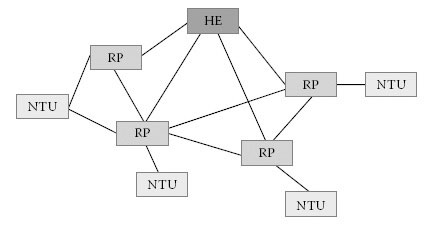
FIGURE 13.15
Example of an AC network.
In order to address stations in a network properly, every station needs a unique identifier. Because the use of standard 48-bit-long Ethernet MAC address would generate unnecessary frame overhead, the IEEE 1901 FFT AC system makes use of its local cell infrastructure and an own addressing method; every cell is given a short network identification (SNID). The six-bit-long SNID enables the differentiation of 63 neighbouring networks. Within a cell, a station is uniquely identified by the TEI. The 12-bit-long TEI supports 4078 stations within a single cell. The remaining address space is reserved for the indication of a new station, the HE and broadcast messages. The combination of SNID and TEI required to uniquely identify a station within an AC network is only 18 bits long. Compared to the 48-bit Ethernet MAC address, the use of the TEI/SNID combination leads to more efficient address spacing, especially when taking into account that the routing approach of IEEE1901 FFT AC systems needs to maintain and transmit the address information of up to four nodes.
13.6.5 Access Intercell Gateway
A station is usually associated with only one HE using a single TEI/SNID tuple. In order to improve the connectivity between two or more cells, an access intercell gateway (AIG) may be used. A station supporting AIG functionality performs association to all possible cells within range. As a consequence, the AIG obtains multiple identities, one per cell, and provides bridging functionality between these cells. With the use of AIGs, more flexible data transmission is possible by crossing different cells.
Management information, such as time synchronisation, is distributed within a cell using periodic AC beacons. In IH networks, the process of beacon transmission is relatively simple. In the event the cell manager cannot reach all stations, dedicated proxy stations are used to transmit beacon messages to unreached stations.
In AC networks, the beacon transmission is based on a multi-hop mechanism, and a dedicated AC beacon is used to supply the cell.

FIGURE 13.16
Example for BL AD.
The HE starts broadcasting an AC beacon message with the beacon level (BL) field set to zero. Every station that receives this beacon message processes the information contained in the beacon. A station that has already received a beacon message with a lower BL value will ignore the received AC beacon; all other stations will increase the BL by one and retransmit the AC beacon. This procedure is repeated until every station within the cell is reached. By using the BL technique, unnecessary beacon repetition is avoided. Figure 13.16 shows the resultant BLs for a specific network. As mentioned previously, the AD for AC beacons will include more STAs than the data connections in an IEEE 1901 FFT AC network.
In order to minimise the number of BLs, the beacon messages are transmitted using a robust modulation (see also Section 13.3.6) that has an increased transmission range and, respectively, a bigger AD. AC beacons are transmitted periodically to keep the network updated and synchronised and possibly to include new stations to the AC cell. Furthermore, the effective bit-loading estimate (BLE) (an estimate of link quality to the HE), TDMA schedule, state of the backup HE and certain station capabilities belong to the management information distributed by the AC beacon. Figure 13.17 shows the hierarchy resulting from the beacon distribution in Figure 13.16.
The formation of new cells is based on the information distributed in the AC beacon. A new station scans for AC beacons for a period of time. It then uses the effective BLE contained in the AC beacon to derive the best connection to a HE. In order to obtain full functionality, the new station needs to associate and authenticate to a cell. During the association procedure, the HE grants permission to join the cell and provides the station with a TEI. The authentication procedure ensures that the station obtains the NEK that is only valid within a particular cell. The NEK used to encrypt intra-cell data transmission ensures data confidentiality (see also Section 13.4.1).
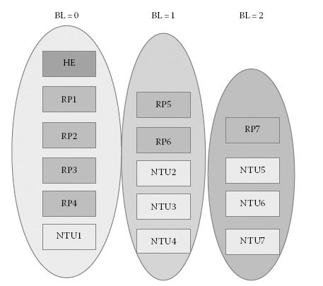
FIGURE 13.17
BL hierarchy.
A station that has already successfully joined a cell keeps receiving AC beacons from neighbouring cells. It will check the information to find out if a neighbouring cell offers a better performance. In that case, it may improve its connectivity by hopping to the neighbouring cell.
In a meshed AC network, almost every device can be backed up using an alternative route. The dynamic construction of cells allows instant restructuring in case one of the devices fails. However, the HE providing the only connection point to the backbone may become a single point of failure. In order to cope with a HE failure, the IEEE1901 FFT AC standard suggests the installation of another HE in the same location working on standby mode. The two HEs appear as a single station, but only one of them is actually active. The other HE remains ready to take over the HE activity in case it detects that the active HE is not responding.
13.7 IEEE 1901 FFT-OFDM Access: Channel Access
13.7.1 Channel Access Management
IEEE 1901 FFT AC provides a mechanism to define time areas for different MAC types. This allows quasi-parallel operation of prioritised bandwidth allocation using carrier sense multiple AC with collision avoidance CSMA/CA and reserved bandwidth allocation using time divisional multiple AC TDMA.

FIGURE 13.18
Channel AC managed by beacon interval.
Figure 13.18 shows the three different regions of a beacon interval, that is, the cell-wide synchronised time interval between two AC beacons is configured into three time slots. The first one, the beacon extent, is reserved to the duration of the beacon transmission.
The second time slot is the contention-free period (CFP), which is used for transmissions that require reserved bandwidth on the TDMA basis.
The third time slot, the contention period (CP), is open for contention channel AC using CSMA/CA.
The system is configurable in a way such that the reserved time for the CFP can be set to zero, and the whole channel AC is used with CSMA/CA.
Different service priorities demanded by HLE applications are mapped to the connection layer using prioritised traffic streams. Different traffic classes determine the level of priority and whether CSMA/CA or TDMA is used for bandwidth allocation.
Figure 13.19 shows a constellation where the CFP is not required, and the whole beacon interval is configured to be a contention period.
In the IEEE 1901 FFT AC standard, CSMA/CA is suggested as the primary protocol for channel AC management. However, the multi-hop structure of an AC network raises the problem of hidden nodes. In order to address this difficulty, a request to send (RTS)/clear to send (CTS) exchange is used to reduce the risk of data collision. Before a station starts a transmission, a RTS packet is sent to the receiving station. In case the required channel can be allocated, the receiving station acknowledges the transition with a CTS packet. Other stations in the same AD are now informed of the scheduled transmission and stop transmitting data into the used AD for a certain period of time.
A major disadvantage of CSMA/CA is the fact that it is based on a statistical algorithm, which does not allow a deterministic channel AC or guarantee of a bandwidth allocation that may be required by certain HLE applications such as audio or video data streams.
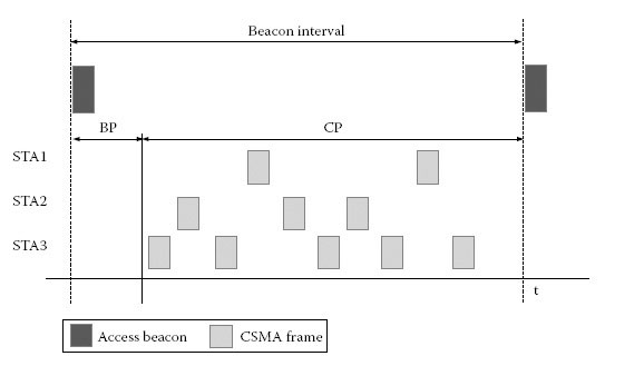
FIGURE 13.19
Pure CSMA mode.
The IEEE 1901 FFT AC standard supports the TDMA in order to meet these concerns and to provide highly consistent bandwidth with exclusive use of the medium.
A station that wants to use the TDMA service requests a channel based on the level of service required by its HLE. The HE then authorises the opening of a TDMA channel within its cell by initiating a remote and distributed procedure where the RPs allocate the required slots. Each RP is then responsible for its allocations according to its available time and bandwidth resources. In the case of a route change between two stations that communicate with each other on the basis of TDMA, a decentralised reallocation procedure ensures the adaption of the TDMA route to the altered situation.
13.8 IEEE 1901 FFT-OFDM Access: Routing
The routing algorithm is responsible for the automatic construction of optimised paths for data transmission based on the underlying network infrastructure. In a distributed network, every station maintains a routing table that maps the final destination of a data packet to its next hop destination. Since the link structure of a power line network is extremely dynamic, the routing algorithm has to adapt to changes of link quality as well as disappearance of stations. Since the IEEE 1901 standard focuses on the PHY and MAC layers, the standard does not specify, but only suggests two different routing methods compatible to the PHY/MAC architecture of the IEEE 1901 standard: the baseline approach and the distance vector approach. Both routing protocols are proactive, that is, the routes are constructed in advance and are updated dynamically.
The baseline approach focuses on building routes toward the HE. In analogy to the process of joining a cell, each station first listens to the AC beacons carrying the neighbours’ connection level information such as the BLE of the link, the hop count toward the HE and the BL. Based on the collected information, each station then selects the next hop station toward the HE. Each station continuously tries to optimise its route toward and from the HE by listening to AC beacons of neighbouring stations possibly carrying changed link-state information. As a result, the baseline routing algorithm dynamically reconstructs a hierarchical network tree optimised for data transmission.
13.8.2 Distance Vector Approach
If data transfer to the HE is dominant, the baseline approach is the best choice. The distance vector approach should be used in turn if communication between arbitrary stations within a cell is dominant. In the distance vector approach, every station maintains a routing table with entries for each station within the cell. The selection of the path is again derived on the basis of the information distributed by the AC beacon.
An unwanted consequence of a varying link structure is the chance that frequent changes of the route may result in a loop. In that case, a data packet is continuously transmitted within a loop without reaching the intended destination. In order to deal with this issue, the header of the data packet contains a hop counter that is initially set to the maximum number of hops and decremented on each retransmission. If a station receives a packet with the hop counter set to zero, it detects the occurrence of the loop and reacts with a route repair procedure.
The HE and the NTUs are located at the edges of the AC cell and provide connectivity to other (possibly non-BPL) networks. In order to support data transfer on the basis of MAC addresses, these stations should support a bridging functionality. To this end, the IEEE 1901 FFT AC frame format uses a dual-layer addressing mechanism. The MAC frame header determines the end-to-end communication by the use of the MAC addresses of the edge devices. The internal header contains the original source TEI (STEI) and the original destination TEI (ODTEI) of the edge stations as well as the STEI and destination TEI (DTEI) of the one-hop transmission. A station that receives a data frame where the ODTEI does not match the station’s TEI transmits the data frame directly to the next hop station without informing the HLE. Bridging tables at the edge stations are used to map the MAC address to the ODTEI and vice versa.
13.9 IEEE 1901 FFT-OFDM Access: Power Management
BPL AC networks normally consist of a large number of stations. As a consequence, the costs of the overall energy supply generated by the whole AC system may become a major financial consideration for the network provider. To address this issue, the IEEE 1901 FFT AC standard defines a sleep mode feature. Due to the complexity of scheduling the sleeping periods over multi-hop distances, the power management in AC networks is more difficult to establish than the one in IH environments. A high number of stations set to sleep mode may increase the risk of network failures due to link changes. The standard suggests either a centralised or a distributed method of power management. In centralised power management, the HE controls the power-saving behaviour of every station within the cell. It determines a periodic power-save cycle as a multiple of the beacon period and assigns a part of this cycle to a station. During this time slot, the station may enter the power-save mode. In distributed power management, the station negotiates with the HE that it intends to be out of service for a certain time (Figure 13.20).

FIGURE 13.20
Timing for the centralised power management.
In this chapter, an overview of IEEE 1901 has been presented. The overall system architecture and the key features of the PHY and MAC layers have been described. IEEE 1901 specifies both high-speed BPL communications for IH and AC systems. IEEE 1901 supports two noncompatible PHY layers that can coexist using an ISP. Although this chapter focused on the widely deployed FFT-based OFDM PHY, a wavelet-PHY and ISP introduction was provided. IEEE 1901 IH and AC use the same FFT-PHY layer with only minor adaptations. The IEEE 1901 FFT-advanced IH PHY and MAC layer features support robust and high-speed transmission of up to 500 Mbit/s at the PHY layer. IEEE 1901 FFT AC defines advanced network architecture capable of fulfilling the present and future requirements for BPL AC systems. Its flexible concept including MAC layer encryption, power management capability and defect prevention predestines its usage in Smart Grid applications. BPL exceeds the narrowband power line technology in terms of robustness and scalability. With CSMA and TDMA, two different channel AC techniques are provided, and thus the support of sophisticated QoS requirements is realised. Since a major challenge of an AC network is the multi-hop environment resulting in a dynamic network topology, bridging and routing concepts are kept highly flexible.
IEEE 1901 FFT AC defines a system capable of fulfilling the present and future requirements of BPL AC systems and their usage in Smart Grid applications.
1. ISO/IEC 7498-1:1994: Information Technology – Open systems interconnection – Basic reference model: The basic model. ISO International Standards, 1994. Available online iso.org/iso/home/store/catalogue_ics
2. Z. Wang and G. B. Giannakis, Wireless multicarrier communications: Where Fourier meets Shannon, IEEE Signal Processing Magazine, 17(3): 29–48, May 2000.
3. R. Prasad, OFDM for Wireless Communication Systems, Artech House, Norwood, MA, 2004.
4. C. Berrou, A. Glavieux and P. Thitimajshima, Near Shannon limit error-correcting coding and decoding: Turbo-codes, IEEE International Conference on Communications, (ICC’93), Geneva, Switzerland, pp. 1064–70, May 1993.
5. C. Berrou and A. Glavieux, Near optimum error correcting coding and decoding: Turbo-codes, IEEE Transactions on Communication, 44: 1261–1271, October 1996.
6. W.E. Ryan, Concatenated codes and iterative decoding, in Wiley Encyclopedia of Telecommunications, J. G. Proakis ed., Wiley & Sons, New York, pp. 556–570, 2003.
7. K. Gracie and M.H. Hamon, Turbo and turbo-like codes: Principles and applications in telecommunications, Proceedings of the IEEE, 95(5): 1228–1254, June 2007.
8. A. D. Rizos, J.G. Proakis and T.Q. Nguyen, Comparison of DFT and cosine-modulated filter banks in multicarrier modulation, in Proceedings of the IEEE Global Communications Conference, (GLOBECOM’94), San Francisco, CA, pp. 687–691, 1994.
9. S. Galli, H. Koga and N. Kodama, Advanced signal processing for PLCs: Wavelet-OFDM, in IEEE International Symposium on Power Line Communications and its Applications (ISPLC), Jeju Island, Korea, April 2–4, pp. 187–192, 2008.
10. IEEE Std 1901–2010: IEEE standard for broadband over power line networks: Medium access control and PHY layer specifications, IEEE Standards Association, 2010. Available online http://standards.ieee.org/store.
11. C. Douillard and C. Berrou, Turbo codes with rate-m/(m+1) constituent convolutional codes, IEEE Transactions on Communications, 53(10): 1630–1638, October 2005.
12. C. Weiss, C. Bettstetter, S. Riedel and D. J. Costello, Jr., Turbo decoding with tail-biting trellises, in Proceedings of the International Symposium on Signals, Systems, and Electronics (ISSSE-98), Pisa, Italy, pp. 343–348, 1998.
13. C. Douillard and C. Berrou, Turbo codes with rate-m/(m+1) constituent convolutional codes, IEEE Transactions on Communications, 53(10): 1630–1638, 2005.
14. T. Lestable, E. Zimmerman, M.-H. Hamon and S. Stiglmayr, BlockLDPC codes vs. Duo-binary turbo-codes for European next generation wireless systems, in Proceedings of the 64th IEEE Vehicular Technology Conference (VTC’06), Montreal, Quebec, Canada, pp. 1–5, 2006.
15. IEEE Std 802.1Q-1998: IEEE standard for local and metropolitan area networks: Virtual bridged local area networks, IEEE Standards Association, 1998.
16. IEEE Std 802-2001: IEEE standard for local and metropolitan area networks: Overview and architecture, IEEE Standards Association, 2002.
17. IEEE Std. 802.1D-2004: IEEE standard for local and metropolitan area networks: Media access control (MAC) Bridges, IEEE Standards Association, 2004.
*. IEEE 1901–2010. Copyright © 2010 IEEE. All rights reserved. Reprinted with permission from IEEE.