
Current Power Line Communication Systems: A Survey
CONTENTS
10.3.1 IEEE 1901 and ITU-T G.hn
10.3.4 BB-PLC Coexistence and Interoperability
10.1 Introduction*
The idea of using power lines also for communication purposes has already been around since the beginning of the last century [6,7]. It is now broadly referred to as power line communications (PLCs). The obvious advantage is the widespread availability of electrical infrastructure, so that theoretically, deployment costs are confined to connecting modems to the existing electrical grid. Following the nomenclature introduced in [8], power line technologies can be grouped into the following:
1. Ultra narrowband (UNB) technologies operating at very low data rate in the ultra- low-frequency band (ULF, 0.3–3 kHz) or in the upper part of the super-low-frequency band (SLF, 30–300 Hz). Examples of UNB-PLC are ripple carrier signalling (RCS) [6], the turtle system [9] and the more recent two-way automatic communications system (TWACS) [10,11]. Especially, automated meter reading (AMR) systems frequently used UNB-PLC technologies to gain access and in parts control over the energy meters within private homes. UNB-PLC systems are usually designed to communicate over long distances with their signals passing through low-voltage/medium- voltage transformers. This helps to keep the amount of required modems and repeaters to a minimum. Drawbacks are low data rates, for example, in the order of 0.001 bit/s (Turtle) and 2 bits per mains frequency cycle (TWACS)*. Additionally, these systems are sometimes limited to unidirectional communications.
2. Narrowband (NB) technologies operate in the very-low-, the low- and in parts of the medium-frequency (VLF/LF/MF) bands, which include the European Comité Européen de Normalisation Électrotechnique (CENELEC) bands (3–148.5 kHz), the US Federal Communications Commission (US FCC) band (10–490 kHz), the JP Association of Radio Industries and Businesses (ARIB) band (10–450 kHz) and the Chinese band (3–500 kHz). Within this class of NB-PLC, one may further subdivide into the following:
a. Low data rate (LDR), which refers to technologies capable of data rates of a few kbit/s. These technologies are usually based on single-carrier or spread-spectrum modulation. Typical examples of LDR NB-PLC technologies are devices conforming to the recommendations: ISO/IEC 14908-3 (LonWorks), ISO/IEC 14543-3-5 (KNX), CEA-600.31 (CEBus), IEC 61334-3-1, IEC 61334-5 (FSK and spread-FSK). They are backed by Standard Development Organisations (SDOs), precisely by the International Electrotechnical Commission (IEC) and the International Organization for Standardization (ISO). Additional non-SDO-based examples are Insteon, X10, HomePlug C&C, SITRED, Ariane Controls and BacNet. LDR NB-PLC technologies have also been referred to as distribution line carrier or power line carrier.
b. High data rate (HDR) refers to technologies capable of data rates ranging between tens of kbit/s and around 500 kbit/s. Today, HDR technologies are based on orthogonal frequency division multiplexing (OFDM) [12]. Typical examples of HDR NB-PLC technologies are those included in the family of approved International Telecommunications Union – Telecommunication Standardization Sector (ITU-T) NB-PLC Recommendations [13–15] and the ongoing Institute of Electrical and Electronics Engineers (IEEE) P1901.2 project [16]. Original non- SDO-based examples are the industry specifications G3-PLC and Powerline- Related Intelligent Metering Evolution (PRIME), which have recently become ITU-T Recommendations G.9903 and G.9904, respectively.
3. Broadband (BB) technologies operate in the medium-, high- or very-high-frequency (MF/HF/VHF) bands (1.8–250 MHz) and have a physical layer (PHY) rate ranging from several Mbit/s to several hundred Mbit/s. Typical examples of BB-PLC technologies are devices conforming to TIA-1113 (HomePlug 1.0), IEEE 1901 and ITU-T G.hn (G. 9960–G. 9964) standards. Additional non-SDO-based examples are HomePlug AV2, HomePlug Green PHY, UPA Powermax and Gigle MediaXtreme. BB-PLC technologies devoted to ‘last mile’ and access applications have also sometimes been referred to as broadband over power lines (BPL).
An overview of UNB-, NB- and BB-PLC specifications and standards is presented in Figure 10.1. Apart from the systems in Figure 10.1, the company Watteco [17] developed a technology called Watt pulse communication (WPC), which does not easily fit into the aforementioned UNB/NB/BB categorisation. WPC roughly occupies the band from 500 kHz up to 7 MHz while at the same time transmitting LDR around 10 up to 50 kbit/s. The transmitter shortcuts the AC with a defined impedance which produces spikes on the mains. The information to be broadcasted is given in the timing relation between individual spikes. Systems can be realised with very low component cost, as the transmitter does not require a digital-to-analogue converter (DAC) or an amplifier [18]. Although interesting for a plurality of command and controls (C&C), and Smart Home applications, controlling electromagnetic compatibility (EMC) or implementing frequency notches (see, Chapter 22) is very difficult for such WPC-PLC systems.
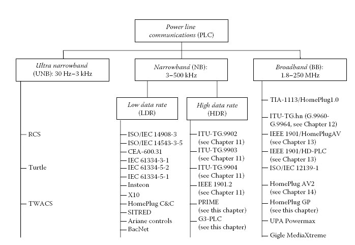
FIGURE 10.1
Overview of UNB-, NB- and BB-PLC specifications and standards.
Leaving UNB-PLC and WPC at the sideline, this chapter provides an overview of current NB-PLC and BB-PLC systems in Sections 10.2 and 10.3, respectively. Further details on the NB-PLC systems IEEE 1901.2 and the family of ITU-T NB-PLC Recommendations are presented in Chapter 11. Details on ITU-T G.hn, IEEE 1901 and HomePlug AV2 may be found in Chapters 12 through 14, respectively.
NB-PLC systems usually operate in the frequency range from 3 to 500 kHz, that is, the CENELEC/ARIB/FCC bands. A pioneering LDR NB-PLC system is definitely LonWorks. While today’s PLC standards only specify one or two of the ISO-Open Systems Interconnection (ISO-OSI) layers, the LonWorks system includes all seven tiers from programming networked applications down to the physical media power line, twisted pair, RF and fibre optics. After becoming an ANSI standard, international organisations agreed to approve it as ISO/IEC 14908-3 [19,20]. LonWorks PLC transceivers are designed to operate in one of two frequency ranges depending on the end application. When configured for use in electric utility applications, the CENELEC A-band is used, whereas in-home/commercial/industrial applications use the C-band. Achievable data rates are in the order of few kbit/s.
Another LDR NB-PLC standard is ISO/IEC 14543-3-5 (KNX, EN 50090) [21]. It spans all layers of the OSI model and can, besides over power line, also be used over other media such as twisted pair and in some cases even wirelessly.
The most widespread NB-PLC technologies deployed today are based on frequency shift keying (FSK) or spread-FSK as specified in the IEC 61334-5-2 [22] and IEC 61334-5-1 [23] standards, respectively. The availability of standards for these technologies goes from the stack of PHY communications protocols up to the application layer (IEC 62056-53 for Companion Specification for Energy Metering [COSEM]) [24], thus facilitating the development of interoperable solutions. Such advanced metering infrastructure (AMI) solutions are now provided by a number of companies and are widely and successfully applied by utilities.
Due to the increasing desire for higher data rates and the growing attention that smart metering projects are getting in various national efforts directed at modernising the aging power grid toward a Smart Grid [2,8], there is today a renewed interest in HDR NB-PLC solutions operating in the CENELEC/FCC/ARIB bands. This section on NB-PLC will primarily focus on current HDR-PLC systems. As in many other communication systems, OFDM has emerged as the modulation scheme of choice. Examples of HDR NB-PLC systems are G3-PLC [25] and PRIME [26] that were initially designed as proprietary technologies within industry alliances, specifically, the G3-PLC Alliance and the PRIME Alliance, but have recently become International standards as ITU-T Recommendation G.9903 [14] and ITU-T Recommendation G.9904 [15], respectively. The processing power requirements of HDR NB-PLC are moderate, so that implementation of multiple technologies in the same device is possible, for example, via digital signal processing (DSP) platforms. This allows for upgrade- ability via software updates, and can especially be an advantage when considering that Smart Grid devices have a very long obsolescence horizon and utilities rely on equipment in the field for a few decades [8]. The technically challenging bits are related to higher layers where hundreds or even thousands of, for example, smart energy meters are connected to a single PLC network. With respect to coexistence, the US National Institute of Standards and Technology (NIST) priority action plan 15 (PAP15) working group* recently approved that newly developed NB-PLC standards shall all implement a coexistence protocol as to ‘have minimal performance impact on the existing deployed devices’, that is, devices using ISO/IEC 14543-3-5 or a standard from the IEC 61334 family [27]. Furthermore, the PAP15 working group also agreed to mandate a single NB-PLC coexistence protocol for the newer OFDM- based technologies. This NB-PLC coexistence protocol is being specified in IEEE P1901.2.
In the next subsections, we give an overview of PRIME and G3-PLC, whereas more details on IEEE P1901.2 [16] and the family of NB-PLC ITU-T Recommendations [13–15] will be given in Chapter 11. PRIME and G3-PLC were both designed initially as proprietary technologies by the PRIME Alliance and the G3-PLC Alliance, respectively, and are mentioned here for historical reasons since they were the first OFDM-based HDR NB-PLC to be developed.
PRIME was developed within the PRIME Alliance, with its steering committee chaired by the Spanish utility Iberdrola [28]. In 2012, PRIME version 1.3.6 became an international standard – see ITU-T Recommendation G.9904 [15].
The PRIME system uses a total of 96 ODFM subcarriers over the frequencies from 42 to 89 kHz, that is, within the CENELEC A-band. Further, it deploys differential binary, quaternary and eight phase shift keying (BPSK, QPSK and 8PSK) and an optional 1/2 rate convolutional code. Therewith, it is able to achieve a PHY peak data rate of 128.6 kbit/s [29]. The OFDM symbol interval is of 2240 μs including a 192 μs cyclic prefix which suffices to deal with most common power line delay spreads. In order to deal with unpredictable impulsive noise, PRIME offers the option to implement automatic retransmission request (ARQ), based on the selective repeat mechanism [30].
Turning to the system architecture, PRIME is forming subnetworks, where each subnet-work has one base node and several service nodes. The base node is the ‘master’ that manages the subnetwork’s resources and connections using a periodically sent beacon signal. The base node is further responsible for PLC channel access arbitration. A contention-free and a contention-based access mechanism exists, whose usage time and duration are decided by the base node. Within the contention-free time division multiplex (TDM) channel access period, the base node assigns the channel to only one node at a time. The contention-based access uses carrier sense multiple access with collision avoidance (CSMA/CA) [26,29].
To interface medium access control (MAC) and application layer, PRIME defines a convergence layer (CL) between the two. The CL can be split into a common part convergence sublayer (CPCS) and a service-specific convergence sublayer (SSCS). The CPCS performs tasks of data segmentation and reassembling and is adjusted to the specific application. Three SSCS are currently defined: The ‘NULL Convergence Sublayer provides the MAC layer with a transparent way to the application, being as simple as possible and minimising the overhead. It is intended for applications that do not need any special convergence capability’. ‘The IPv4 Convergence Layer provides an efficient method for transferring IPv4 packets over the PRIME network’.
Finally, the IEC 61334-4-32 CL ‘supports the same primitives as the IEC 61334-4-32 standard’ [31], making it easy, for example, to support advanced metering applications that make use of the standardised data models of IEC 62056-62 [32]. PRIME could therefore also be used to replace the aging PHY and MAC layer of the single-carrier power line standard IEC 61334-5-1 [23], also known as S-FSK.
The other OFDM-based HDR NB-PLC specification G3-PLC [33–35] was published in August 2009. In 2012, members of the G3-PLC Alliance brought the original G3-PLC specs into the ITU-T where they were enhanced and additional functionalities were added. The enhanced G3-PLC became an International Standard in 2012 as ITU-T Recommendation G.9903 [14].
G3-PLC can be configured to operate in the internationally accepted bands from 10 to 490 kHz (FCC, CENELEC, ARIB). Using differential BPSK, QPSK and 8PSK for constellation mapping, time–frequency interleaving, concatenated convolutional Reed–Solomon forward error correction (FEC) and the option of robust modes (ROBO, for robust OFDM), it reaches PHY peak data rates close to 300 kbit/s. Peak and typical data rates for various frequency bands have been reported in [36]. A comparison of the rates achievable by all the HDR NB-PLC technologies considered here is also given in Tables 11.2 and 11.3.
The MAC layer is based on IEEE 802.15.4-2006 [37]. 6LoWPAN [38] is used to adapt the IEEE 802.15.4-2006 MAC to IPv6 [39]. This allows the application layer to comply with ANSI C12.19/C12.22 [40], or IEC 62056-61/62 (DLMS/COSEM) [41,42] to run standard Internet services. A detailed description of the additional features that were introduced in G.9903 is given in Chapter 11.
A comparison between PRIME and G3-PLC, mainly focusing on PHY aspects, is presented in [43]. There it is found that G3-PLC performs much more robustly than PRIME, while PRIME’s design paradigm is low complexity. Additional considerations on the comparison of the various NB-PLC technologies are also made in Section 11.7.
In the last decade, BB-PLC chips by semiconductor vendors, such as Intellon*, DS2†, Gigle† and Panasonic, came to market that operate in the band from around 2 to 86 MHz and, in some cases, optionally up to 300 MHz. The chips are mainly based on three consortia backed specifications developed within the frameworks of the HomePlug Powerline Alliance (HomePlug), the Universal Powerline Association (UPA) and the High-Definition Power Line Communication (HD-PLC) Alliance. Related products allow data rates around 200 Mbit/s and are not interoperable.
However, to make BB-PLC systems a broad success, internationally adopted standards became essential. The ITU-T, as well as the IEEE, commenced work on such next-generation standards, namely, ITU-T G.hn [44] and IEEE 1901 [45].
ITU-T G. hn is not only applicable to power lines but also to phone lines and coaxial cables, therewith for the first time defining a single standard for all major wireline communications media. At the end of 2008, the PHY layer and the overall architecture were consented in ITU-T Recommendation G.9960 [46]. The data link layer (DLL) Recommendation G.9961 [47] was approved in June 2010, and a multiple-input multiple-output (MIMO) transceiver extension G.9963 was consented in September 2011 [48]. Alongside, the HomeGrid Forum was founded to promote the ITU-T G.hn standard and to address certification and interoperability issues [49]. Details on ITU-T G. hn may be found in Chapter 12.
Simultaneously, IEEE P1901 [50] was working on the ‘Standard for Broadband over Power Line Networks: Medium Access Control and Physical Layer Specifications’ [51]. It covers the aspects access, in-home, as well as coexistence of access–in-home and in-home–in-home networks, and the official IEEE standard 1901-2010 was published in December 2010. To assure a broad industrial backing of IEEE 1901, two optional PHY technologies, namely, FFT-PHY (based on HomePlug AV) and wavelet-PHY (based on HD-PLC), were included in the standard. The two resulting PHY layers are not interoperable, but a mandatory coexistence protocol, inter-system protocol (ISP), was included to assure their coexistence. The HomePlug Powerline Alliance [52] serves as the certifying body for IEEE 1901 FFT-PHY compliant products, whereas the HD-PLC Alliance serves as the certifying body for IEEE 1901 wavelet-PHY compliant products. While IEEE 1901 wavelet-PHY/HD-PLC is presently mainly used on the JP market, IEEE 1901 FFT-PHY/HomePlug AV is used in many countries around the globe, with products of the HomePlug family currently possibly being the most deployed BB-PLC technology worldwide. Details on IEEE 1901 may be found in Chapter 13.
In analogy to the introduction of MIMO to ITU-T G.hn, the HomePlug Alliance introduced the HomePlug AV2 specification in January 2012. The HomePlug AV2 specification includes features like MIMO with beamforming, an extended frequency range of up to 86 MHz, efficient notching, several transmit power optimisation techniques, 4096-quadrature amplitude modulation (QAM), power save modes, short delimiter and delayed acknowledgement, boosting the maximum PHY rate to around 2 Gbit/s (see Chapter 14 for details). Further, to cover multiple home networking media under one umbrella, IEEE P1905.1 devised a ‘Standard for a Convergent Digital Home Network for Heterogeneous Technologies’ [53]. It defines an abstraction layer for multiple home networking technologies like IEEE 1901, IEEE 802.11 (Wi-Fi), IEEE 802.3 (Ethernet) and MoCA 1.1 and is extendable to work with other home networking technologies. Further details on IEEE 1905.1 may be found in Chapter 15.
10.3.1 IEEE 1901 and ITU-T G.hn
IEEE 1901 uses the band from 2 MHz up to 50 MHz with services above 30 MHz being optional. ITU-T G. hn (G.9960/G.9961) operates from 2 up to 100 MHz using bandwidth scalability, with three distinct and interoperable bands defined as 2–25, 2–50 and 2–100 MHz. The architectures defined by IEEE 1901 and ITU-T G.hn (G.9960/G.9961) are similar in several aspects. In ITU-T G.hn, one refers to a subnetwork as domain. Operation and communication are organised by the domain master who communicates with various nodes. Similarly, the subnetwork in IEEE 1901 is referred to as basic service set (BSS). The equivalent to the domain master is the BSS manager, which connects to the so-called stations. These network items with their system-specific terminology are summarised in Table 10.1.
Even if many features appear to be individually developed by ITU-T and IEEE, several are actually identical. The fact that ITU-T G.hn and IEEE 1901 largely agree on channel coherence time, coherence bandwidth, guard interval, roll-off window timings, etc. shows that the BB-PLC channel is analysed similarly and that channel difference for comparable topologies is not very different around the globe. Similarities continue with PHY-frame header settings making use of QPSK, FEC code rate 1/2 and repetition codes. The segmentation process of embedding the application data into PLC convenient packets is similar and data are in both cases encrypted using AES-128 [54]. The MAC cycle or beacon period is selected to be two line cycles. The bit loading of carriers can be line cycle–dependent and immediate, and delayed acknowledgments are possible.
If ITU-T G.hn and IEEE 1901 modems are installed in the same home, one transmission is an unintended interferer for the other one. Confusion is avoided due to different preambles that are sent at the beginning of a frame. A correlator at the receiver is able to identify precise timing information of a frame by detecting the inverted transmitted preamble symbols. A PLC transmission is identified by verifying the timing results of the correlated received signals with an ITU-T G.hn or an IEEE 1901 mask. A multi-mode receiver could identify both correlation masks and could forward the subsequent data signals to the corresponding decoding chain.
Another likely scenario is that same technology networks exist in close proximity, with the risk of the so-called neighbouring network interference. To deal with neighbouring network interference, ITU-T G.hn uses different preamble symbol seeds in each network. Therewith, ITU-T G.hn networks are able to coexist and communicate simultaneously, that is, not using time division. Instead, link adaptation procedures adjust the throughput to cope with degraded signal to interference plus noise ratios (SINR). In many cases, the throughput will be throttled only slightly allowing ITU-T G.hn networks to coexist nearly unimpeded. On the other hand, IEEE 1901 relies on a CSMA/CA medium access strategy, which may lead to an increased number of collisions. As countermeasure, IEEE 1901 introduces a coordinated mode that allows neighbouring networks to allocate times over the shared medium for specific communications. This coordinated time division multiple access (TDMA) mode enables traffic to get through unimpeded albeit at the price of time division (orthogonal throughput sharing).
Synopsis of Terms used in the BB-PLC Standards ITU-T G.hn and IEEE 1901
Item |
ITU-T G.hn |
IEEE 1901 |
Subnetwork |
Domain |
BSS |
Transceiver |
Node |
Station (STA) |
Subnetwork controller |
Domain master (DM) |
BSS manager/central coordinator (CCo) |
Layer 2 (L2) of the OSI model |
Data link layer (DLL) including application, protocol convergence |
Medium access control (MAC) with isolated convergence layer |
Relaying transceiver |
Relay (L2) |
Repeater (L2) |
Network controller proxy |
Relay (assigned as a proxy) |
Proxy BSS manager |
Allocated frequencies |
Frequency bandplan |
Spectrum mask |
Time frame |
MAC cycle |
Beacon interval |
Time between frames |
Inter-frame gap |
Inter-frame space |
Synchronisation and training symbol |
Preamble |
Preamble |
Information broadcasted at the beginning |
PHY-frame header (168 bit) |
Frame control (128 bit) |
Robust transmission |
Robust communication mode (RCM) |
Robust OFDM (ROBO) mode |
SINR estimation signals |
Probe |
Sound |
SINR feedback info |
Bit allocation table (BAT) |
Tone map |
Smallest data packet |
Logical link control (LLC) protocol data unit (LPDU) |
PHY block |
Encryption responsible |
LLC |
BSS manager |
Link set-up and QoS responsible |
DLL management |
Connection manager |
Access method |
CSMA/CA, TDMA, STXOP (shared transmission opportunities) |
CSMA/CA, TDMA |
Access control schedule |
Media access plan (MAP) |
Beacon |
Interface to higher layers |
A-Interface |
H1 Interface |
Source: Extended from Table 7.7 in Berger, L.T., Smart Grid – Applications, Communications and Security, Berger, L.T. and Iniewski, K., Eds., John Wiley & Sons, Hoboken, NJ, April 2012, ch. 7. Copyright © 2012 John Wiley & Sons. With permission.
Set aside these minor differences, two very different FECs, that is, low-density parity-check code (LDPC) in ITU-T G.hn and Turbo Code in IEEE 1901, were chosen – see [55] for a comparative analysis. Some have argued that this makes it more difficult (or costly) to implement both standards in a single chip, as the FEC part is up to the present day a non-negligible cost/space factor when manufacturing wafers. However, dual mode devices have already started to appear on the market.
In terms of data rate and silicon cost, the full-fletched ITU-T G.hn and IEEE 1901 systems are targeting primarily in-home data delivery, web browsing as well as audio and video distribution. To offer an alternative to automation and energy management tasks with respect to HDR NB-PLC as introduced in Section 10.2, ITU-T G.hn includes a low complexity profile (LCP), while HomePlug developed on the basis of IEEE 1901 the HomePlug Green PHY specification. These are outlined in the following two subsections, respectively.
It is envisioned that G.hn nodes are in the future embedded into Smart Grid home (SGH) area network devices. SGH nodes will typically make use of the ITU-T G. hn LCP, operating in the frequency range from 2 to 25 MHz while still being interoperable with the full G.hn profile. This allows for reduced component cost and power consumption. Example SGH nodes could be heating and air-conditioning appliances, as well as plug-in electric vehicles (PEVs) and electric vehicle supply equipment (EVSE). Together they form a multi-domain home area network (HAN).
The SGHs interact with the utility’s access network (UAN) and its AMI through an energy service interface (ESI). The AMI domain comprises AMI meters (AMs), AMI submeters (ASMs), as well as an AMI head end (HE). The HE is a local hub (concentrator) that controls all meters downstream from it and interfaces to the utility’s wide area/backhaul network upstream from it. Each AMI HE supports up to 250 AM and/or ASM nodes forming an AMI domain (in dense urban areas, 150–200 m is a frequently encountered maximum). Further, a network supports up to 16 AMI domains, delivering support for up to 16 × 250 = 4000 AMI devices. The ability to support 16 domains with 250 nodes each is a general property of G.hn not limited to Smart Grid/AMI applications. Domains may be formed over any kind of wiring. The nodes within a domain are grouped into SGH and non-SG nodes. For security reasons, non-SG nodes are logically separated from SGH nodes using a secure upper-layer protocol.
In every domain, there is a domain master that coordinates operation of all nodes. G.hn nodes of different domains communicate with each other via inter-domain bridges (IDBs). IDBs are simple data communications bridges on OSI Layer 3 and above, enabling a node in one domain to pass data to a node in another domain. In a multi-domain situation, a global master (GM) provides coordination of resources, priorities and operational characteristics between G.hn domains. Besides, ITU-T G.hn domains can be bridged to alien (non-G.hn) domains, for example, to IEEE 1901/1901.2 and wireless technologies. For example, besides the UAN/AMI connection through the ESI, the HAN might be connected to the outside world via a digital subscriber line or cable modem gateway communicating with the ITU-T G.hn HAN via an alien domain bridge.
In analogy to the ITU-T G.hn LCP, the HomePlug Powerline Alliance has released the HomePlug GreenPhy (Home Plug GP) specification. HomePlug GP is a subset of HomePlug AV that is intended for use within Smart Grid applications. It was developed specifically to support applications on the HAN within the customer premises. A means of reducing cost and power consumption has to be found while maintaining HomePlug AV/IEEE 1901 interoperability, as well as preserving reliability and coverage. Optimised for low- power applications and costs, HomePlug GP uses the most robust communication mode of HomePlug AV technology. OFDM carrier spacing, preamble, frame control and FEC are identical to HomePlug AV/IEEE 1901 resulting in identical coverage and reliability. CSMA/CA is used as channel access scheme. Further, nodes may use long power save periods if a higher latency is acceptable. In the sleep state, modems have only a 3% power consumption compared to the awake time resulting in an average power reduction of >90% with respect to standard HomePlug AV products.
One of the biggest differences between HomePlug AV and HomePlug GP is the peak PHY rate. HomePlug AV supports a peak PHY rate of 200 Mbit/s, which is simply not required for Smart Grid applications. Based on extensive discussion with the utility industry, it was learned that coverage and reliability were paramount considerations. Peak data rate could be reduced, which in turn would allow for reductions in both cost and power consumption. HomePlug GP supports a peak PHY rate of 10 Mbit/s, which is the result of two key simplifications:
1. Restriction of OFDM subcarrier constellation mapping to QPSK
2. Restriction to data rates supported by ROBO (robust OFDM) modes, thereby eliminating the need for adaptive bit loading and management of tone maps
By making exclusive use of QPSK, the analogue front-end and line driver requirements (linearity and converter resolution) are less stringent. As a result, HomePlug GP devices should be able to achieve a higher level of integration, including single-chip architectures, which will help reduce cost and footprint.
The HomePlug GP MAC shares the same CSMA and priority resolution mechanisms as HomePlug AV. It does not, however, support the optional TDMA mechanism.
These measures were essential to enable low-cost, low-power devices that interoperate with HomePlug AV/IEEE 1901 while maintaining the same robust coverage and reliability. A comparative overview on the differences between HomePlug AV and HomePlug GP is presented in Table 10.2.
There are some features that are unique to the HomePlug GP MAC. In order to ensure that HomePlug GP devices would not adversely affect network throughput of HomePlug. AV devices, an ad hoc bandwidth sharing algorithm that limits HomePlug GP’s time on wire (ToW) was included in the HomePlug GP specifications. In addition, a specific routing protocol was implemented allowing for repeater functionality. A novel power-saving mechanism was also added. Finally, a method for characterising signal-level attenuation was included to facilitate association and binding of electric vehicles with charging equipment in public parking areas.
HomePlug AV and HomePlug GreenPhy Comparison
Parameter/Function |
HomePlug AV |
HomePlug GP |
Frequency spectrum |
2–30 MHz |
2–30 MHz |
Frequency division multiplexing |
OFDM |
OFDM |
Number of subcarriers |
1155 |
1155 |
Subcarrier spacing |
24.414 kHz |
24.414 kHz |
Bit-loading constellation mapping |
BPSK, QPSK, 16 QAM, 64 QAM, 256 QAM, 1024 QAM |
QPSK |
FEC type |
Turbo code |
Turbo code |
FEC rate |
1/2 and 16/21 (punctured) |
1/2 |
Robust mode data rate |
4–10 Mbit/s |
4, 5 and 10 Mbit/s |
Adaptive bit-loading data rate |
20–200 Mbit/s via pre-negotiated tone maps |
No (instead use of mini ROBO 3.8 Mbit/s, standard ROBO 4.9 Mbit/s and high-speed ROBO 9.8 Mbit/s) |
Channel access |
CSMA/CA with optional TDMA |
CSMA/CA |
Central coordinator capability |
Yes |
Yes (limited modes) |
Power save mode |
No |
Yes (identical to HomePlug AV2) |
Bandwidth sharing |
No (channel access CSMA/CA, TDMA) |
Distributed bandwidth control (DBC) |
Source: Based on HomePlug Powerline Alliance, HomePlug Green PHY 1.1 – The standard for In-Home Smart Grid Powerline Communications: An application and technology overview, HomePlug Powerline Alliance, Technical Report, October 2012, white Paper, Version 1.02, http://www.homeplug.org/tech/whitepapers/HomePlug_Green_PHY_whitepaper_121003.pdf (accessed February 2013). Copyright © 2012 HomePlug Powerline Alliance, Inc. With permission.
If the slower HomePlug GP devices operating in the presence of heavy HomePlug AV voice or video traffic were able to access the medium in an unconstrained manner, it is possible that HomePlug AV throughput could be adversely affected. As a countermeasure, distributed bandwidth control (DBC) was developed. When traffic at various channel access priorities (CAP) is detected, DBC will limit aggregate HomePlug GP channel access time, or ToW to ∼7%. This corresponds to an effective PHY rate of 700 kbit/s (7% ToW at 10 Mbit/s) and a MAC throughput rate of 400–500 kbit/s, which provides ample capacity for Smart Grid applications. HomePlug GP clients monitor all HomePlug GP transmissions in a two line cycle sliding window that immediately precedes any attempt to contend for channel access. This is possible because HomePlug GP packets have a special flag in the start of frame (SoF) delimiter. If the pending packet will cause aggregate HomePlug GP ToW to exceed 7%, the HomePlug GP client cannot contend for channel access at a CAP3 (highest) priority and must wait for an ensuing channel access opportunity or the next window. In most instances, the local medium will not be completely occupied. HomePlug GP devices may exploit unused ToW by contending for channel access at CAP0 (lowest priority). HomePlug GP equipment installed in locations in which HomePlug AV equipment is not present may occupy up to 100% ToW.
The routing and repeating feature implemented in HomePlug GP is interoperable with the repeating functionality specified in IEEE 1901 (see Chapter 13). The main purpose of the repeating functionality is to provide an extension of the HomePlug network coverage when some stations in the network are too distant to allow error-free communication. To support repeating, each HomePlug GP station maintains a local routing table (LRT), containing routing information for every associated station in the network. The table includes information such as the identifier of the next station through which to route, the route data rate (RDR) and the route number of hops (RNH). Regularly, a specific procedure updates the routing tables. New routes can be selected, depending on the computed RDR and RNH for the candidate routes.
As already introduced in connection with ITU-T G.hn LCP, PEV charging is a major Smart Grid application, with upcoming need to provide charging facilities at home, at work and in public parking areas. In order to ensure error-free billing, it is necessary to unambiguously resolve which PEV is physically connected to a charging spot, that is, an EVSE. In order to reliably perform PEV/EVSE association, a special feature called signal-level attenuation characterisation (SLAC) was designed into HomePlug GP. A PEV invokes SLAC broadcasting a message. Any available EVSE within hearing range computes the PEV’s signal strength and reports back. The EVSE with the highest received signal strength is identified as the correct EVSE, and the two devices set-up a private network for the duration of the charging session. Details of how to use HomePlug GP SLAC in automotive applications can be found in ISO/IEC 15118-3 [56].
Finally, reduced power consumption is a critical factor for Smart Grid applications. A special power save mode has hence been implemented within HomePlug GP. This power save mode is also an integral part of HomePlug AV2 with details described in Chapter 14.
10.3.4 BB-PLC Coexistence and Interoperability
Despite the similarities between the BB-PLC systems, one should note that G.hn defines a PHY/DLL used for operation over any wireline medium. The OFDM parameters are adjusted to account for different medium-dependent channel and noise characteristics and to allow for straightforward scaling when adjusting the parameters between one and another medium. On the contrary, IEEE 1901 defines two disparate PHY/MAC technologies based on HomePlug AV and HD-PLC. One of the key differences is their frequency division multiplexing scheme. The HomePlug AV-based version uses the fast Fourier transform (FFT), while the HD-PLC-based version uses wavelets. Hence, they are sometimes also referred to as FFT-PHY and wavelet-PHY, respectively. A special coexistence mechanism has to be used when operating IEEE 1901 devices from both PHYs on the same power line which is standardised within IEEE 1901 as ISP (see also [57,58]). A nearly identical mechanism was standardised by ITU-T in Recommendation G.9972 [59], also known as G.cx. Technical contributions to ITU-T and IEEE from members of the NIST PAP15 assured the alignment of both standards. As a result, the NIST PAP 15 recommended to mandate that all BB-PLC technologies implement Recommendation ITU-T G.9972 or ISP [60] (see also [8] Sect. III. E.).
The ISP protocol allows a TDM scheme to be implemented between coexisting in-home systems and between coexisting in-home and access systems. Each of the PLC system categories is allocated a particular ISP window in a round robin fashion. The allocation is determined by (1) the number of systems on the power line, (2) the type of the systems present and (3) the systems’ bandwidth requests. The TDM synchronisation period for the in-home and access systems is defined with the parameter TH in Figure 10.2. There are four ISP time slots (TISP) within a single TH period, one for access modems (ACC), in-home wavelet (IH-W), in-home OFDM (IH-O) and in-home G.hn (IH-G). Each ISP time slot is further divided into three TDM units (TDMUs), leading to a total of 12 TDMUs in each TH period. Each TDMU is further divided into eight TDM slots (TDMSs), labelled TDMS#0 through TDMS#7. Figure 10.2 also illustrates the TDM partitioning relative to the AC line cycles. The ISP window is used to generate and detect the ISP signal that is allocated within the first TDMS#0 in TMDU#0, TMDU#3, TMDU#6 and TDMU#9. The duration of a TDMU is equivalent to the beacon interval/MAC cycle, that is, two AC line cycles.
Coexistence signalling is carried out by the use of periodically repeating ISP signals within the ISP time slots. The phase of the transmitted ISP signal conveys the coexistence information. This set of instantaneous information is termed the network status that defines the allocation of resources to each coexisting system. By monitoring the ISP signal transmitted within the ISP time slots allocated to other systems, a coexisting system is able to determine the number and type of coexisting systems present on the line and their resource requirements. Similarly, by monitoring the signal within its own ISP time slot, a coexisting system is able to detect a resynchronisation request from one of the other coexisting systems. The ISP signal consists of 16 consecutive short OFDM symbols, each of Ts duration. Each symbol is formed by a set of ‘all-one’ BPSK sequences. The 16 symbols are multiplied by a window function with the length of TW to reduce out-of-band energy complying with the transmit spectrum requirement. Since all devices send the signal simultaneously, the ISP signal must be sent with 8 dB less power than the normal transmission.
The TDM synchronisation scheme is used such that each PLC system shares the medium without interfering with others. However, it is possible that two or more systems are synchronised to two or more different, mutually visible ISP sequences [51, Annex R]. In such cases, in order to prevent mutual interference, it is important that they resynchronise to the same ISP sequence. In other words, whenever a BB-PLC device starts up or restarts, it needs to be aware of the presence of any other systems with which it is able to coexist. Accordingly, a start-up and resynchronisation procedure is defined within the ISP.

FIGURE 10.2
Time division multiplexing on ISP and timing parameters. (From Yonge, L. et al., Hindawi J. Electric. Comput. Eng., Article ID 892628,20, 2013, http://downloads.hindawi.com/journals/jece/2013/892628.pdf. Copyright © 2013.)
This chapter provided an overview of UNB-, NB- and BB-PLC systems and standards. It should be noted that more in-depth information on the ITU-T family of NB-PLC Recommendations and IEEE 1901.2 is presented in Chapter 11. Further, Chapters 12 through 14 present details on ITU-T G.hn, IEEE 1901 and HomePlug AV2, respectively. Finally, IEEE 1905.1 enriches home networking by creating a common layer on top of PLC, IEEE 802.11 (Wi-Fi), IEEE 802.3 (Ethernet) and MoCA technologies. This allows seamless hybrid networking increasing the coverage to transport, for example, several high-definition video streams to remote locations within a home (for details, see Chapter 15).
The work has been partially supported by the Spanish Ministry of Science and Innovation (MICINN) Program INNCORPORA-Torres Quevedo 2011.
1. L. T. Berger, Broadband powerline communications, in Convergence of Mobile and Stationary Next Generation Networks, K. Iniewski, Ed. Hoboken, NJ: John Wiley & Sons, 2010, ch. 10, pp. 289–316.
2. L. T. Berger, Wireline communications in smart grids, in Smart Grid – Applications, Communications and Security, L. T. Berger and K. Iniewski, Eds. Hoboken, NJ: John Wiley & Sons, April 2012, ch. 7.
3. HomePlug Powerline Alliance, HomePlug Green PHY 1.1 – The standard for In-Home Smart Grid Powerline Communications: An application and technology overview, HomePlug Powerline Alliance, Technical Report, October 2012, White Paper, Version 1.02, http://www.homeplug.org/tech/whitepapers/HomePlug_Green_PHY_whitepaper_121003.pdf (accessed February 2013).
4. L. T. Berger, A. Schwager and J. J. Escudero-Garzás, Power line communications for Smart Grid applications, Hindawi Publishing Corporation Journal of Electrical and Computer Engineering, Article ID 712376, 1–16, 2013, received 3 August 2012; accepted 29 December 2012, Academic Editor: Ahmed Zeddam, http://www.hindawi.com/journals/jece/aip/712376/.
5. L. Yonge, J. Abad, K. Afkhamie, L. Guerrieri, S. Katar, H. Lioe, P. Pagani, R. Riva, D. Schneider and A. Schwager, An overview of the HomePlug AV2 technology, Hindawi Journal of Electrical and Computer Engineering, Article ID 892628, 20, 2013, http://downloads.hindawi.com/journals/jece/2013/892628.pdf.
6. K. Dostert, Telecommunications over the power distribution grid – Possibilities and limitations, in International Symposium on Power Line Communications and Its Applications (ISPLC), Essen, Germany, April 1997, pp. 1–9.
7. P. A. Brown, Power line communications – Past present and future, in International Symposium on Power Line Communications and Its Applications (ISPLC), Lancaster, UK, September 1999, pp. 1–8.
8. S. Galli, A. Scaglione and Z. Wang, For the grid and through the grid: The role of power line communications in the smart grid, Proceedings of the IEEE, 99(6), 998–1027, June 2011.
9. D. Nordell, Communication systems for distribution automation, in IEEE Transmission and Distribution Conference and Exposition, Bogota, Colombia, April 2008, pp. 1–14.
10. S. Mak and D. Reed, TWACS, a new viable two-way automatic communication system for distribution networks. Part I: Outbound communication, IEEE Trans. Power App. Syst., 101(8), 2941–2949, August 1982.
11. S. Mak and T. Moore, TWACS, a new viable two-way automatic communication system for distribution networks. Part II: Inbound communication, IEEE Trans. Power App. Syst., 103(8), 2141–2147, August 1984.
12. R. van Nee and R. Prasad, OFDM for Wireless Multimedia Communications, ser. Universal personal communication Artech House Publishers, London, U.K., 2000.
13. International Telecommunications Union (ITU) – Telecommunication Standardization Sector STUDY GROUP 15, Narrowband orthogonal frequency division multiplexing power line communication transceivers for G.hnem networks, Recommendation ITU-T G.9902, October 2012.
14. International Telecommunications Union (ITU) – Telecommunication Standardization Sector STUDY GROUP 15, Narrowband orthogonal frequency division multiplexing power line communication transceivers for G3-PLC networks, Recommendation ITU-T G.9903, October 2012.
15. International Telecommunications Union (ITU) – Telecommunication Standardization Sector STUDY GROUP 15, Narrowband orthogonal frequency division multiplexing power line communication transceivers for PRIME networks, Recommendation ITU-T G.9904, October 2012.
16. IEEE 1901.2: Draft standard for low frequency (less than 500 kHz) narrow band power line communications for Smart Grid applications, http://grouper.ieee.org/groups/1901/2/.
17. Watteco, Next generation wireless IP sensors for the Internet of things, http://www.watteco.com/(accessed April 2013).
18. P. Bertrand, O. Pavie and C. Ripoll, Watteco’s WPC: Smart, safe, reliable and low power automation for home, White Paper, La Garde, France, December 2008.
19. American National Standards Institute/Electronic Industries Association (ANSI/EIA), Control network power line (PL) channel specification, September 2006, ANSI/CEA-709.2-A.
20. International Organization for Standardization, Interconnection of information technology equipment – Control network protocol – Part 3: Power line channel specification, January 2011, International Standard ISO/IEC 14908-3, Revision 11.
21. International Organization for Standardization, Information technology – Home electronic system (HES) architecture – Part 3–5: Media and media dependent layers – Powerline for network based control of HES class 1, May 2007, international standard ISO/IEC 14543-3-5, First edition.
22. International Electrotechnical Commission (IEC), Distribution automation using distribution line carrier systems – Part 5-2: Lower layer profiles – Frequency shift keying (FSK) profile, Geneva, Switzerland, Standard IEC 61334-5-2, Ed. 1.0, 1998.
23. International Electrotechnical Commission (IEC), Distribution automation using distribution line carrier systems – Part 5-1: Lower layer profiles – The spread frequency shift keying (S-FSK) profile, Standard IEC 61334-5-1, Ed. 2.0, 2001.
24. International Electrotechnical Commission (IEC), Electricity metering – Data exchange for meter reading, tariff and load control – Part 53: COSEM application layer, Standard IEC 62056-53, Ed. 2, December 2006.
25. Électricité Réseau Distribution France, G3-PLC: Open standard for Smart Grid implementation, http://www.maxim-ic.com/products/powerline/g3-plc/ (accessed April 2013).
26. PRIME Alliance, Draft standard for PoweRline Intelligent Metering Evolution, 2010, www.prime-alliance.org/Docs/Ref/PRIME-Spec_v1.3.6.pdf (accessed March 2013).
27. NIST Priority Action Plan 15, Narrowband PLC coexistence requirement, http://collaborate.nist.gov/twiki-sggrid/pub/SmartGrid/PAP15PLCForLowBitRates/Requirements_on_NB_PLC_coexistence_Final_Oct_11r1.xls (accessed November 2011).
28. PRIME Alliance, Powerline related intelligent metering evolution (PRIME), http://www.prime-alliance.org (accessed March 2013).
29. I. Berganza, A. Sendin and J. Arriola, PRIME: Powerline intelligent metering evolution, in CIRED Seminar 2008: SmartGrids for Distribution. Frankfurt, Germany: CIRED, June 2008, pp. 1–3.
30. A. S. Tannenbaum, Computer Networks, 4th edn. Englewood Cliffs, NJ: Prentice Hall International, 2003.
31. International Electrotechnical Commission (IEC), Distribution automation using distribution line carrier systems – Part 4: Data communication protocols – Section 32: Data link layer – Logical link control (LLC), November 1997.
32. International Electrotechnical Commission (IEC), Electricity metering – Data exchange for meter reading, tariff and load control – Part 62: Interface classes, Standard IEC 62056-62, Ed. 2, November 2006.
33. Électricité Réseau Distribution France (ERDF), G3-PLC physical layer specification, August 2009, http://www.maxim-ic.com/products/powerline/pdfs/G3-PLC-Physical-Layer-Specification.pdf (accessed February 2011).
34. Électricité Réseau Distribution France (ERDF), G3-PLC MAC layer specification, August 2009, http://www.maxim-ic.com/products/powerline/pdfs/G3-PLC-MAC-Layer-Specification.pdf (accessed February 2011).
35. Électricité Réseau Distribution France (ERDF), G3-PLC profile specification, August 2009, http://www.maxim-ic.com/products/powerline/pdfs/G3-PLC-Profile-Specification.pdf (accessed February 2011).
36. K. Razazian, G3-PLC provides an ideal communication platform for the smart gird, in IEEE International Symposium on Power Line Communications and Its Applications (ISPLC), Rio de Janeiro, Brazil, March 2010, keynote Presentation, http://ewh.ieee.org/conf/isplc/2010/KeynoteAndPanelFiles/9-40-KAVEH.pdf (accessed December 2012).
37. Institute of Electrical and Electronics Engineers, Local and metropolitan area networks – Specific requirements part 15.4: Wireless medium access control (MAC) and physical layer (PHY) specifications for low-rate wireless personal area networks (WPANs), September 2006, standard for Information Technology – Telecommunications and Information Exchange Between Systems.
38. Z. Shelby and C. Bormann, 6LoWPAN: The Wireless Embedded Internet. Chichester, U.K.: John Wiley & Sons, November 2009.
39. S. Deering and R. Hinden, Internet protocol, version 6 (IPv6) specification, RFC 2460, December 1998, http://tools.ietf.org/html/rfc2460 (accessed February 2011).
40. American National Standards Institute (ANSI), Utility industry end device data tables, ANSI Standard C12.19, 2008.
41. International Electrotechnical Commission (IEC), Electricity metering – Data exchange for meter reading, tariff and load control – Part 61: Object identification system (OBIS), November 2006, International Standard IEC 62056-61, second edition.
42. International Electrotechnical Commission (IEC), Electricity metering – Data exchange for meter reading, tariff and load control – Part 62: Interface classes, November 2006, International Standard IEC 62056-62, second edition.
43. M. Hoch, Comparison of G3 PLC and PRIME, in IEEE International Symposium on Power Line Communications and Its Applications (ISPLC), Udine, Italy, April 2011, pp. 165–169.
44. V. Oksman and S. Galli, G.hn: The new ITU-T home networking standard, IEEE Commun. Mag., 47(10), 138–145, October 2009.
45. S. Galli and O. Logvinov, Recent developments in the standardization of power line communications within the IEEE, IEEE Commun. Mag., 46(7), 64–71, July 2008.
46. International Telecommunications Union (ITU), ITU-T Recommendation G.9960, Unified highspeed wire-line based home networking transceivers – Foundation, August 2009.
47. International Telecommunications Union (ITU), ITU-T Recommendation G.9961, Data link layer (DLL) for unified high-speed wire-line based home networking transceivers, June 2010.
48. International Telecommunications Union (ITU), ITU-T Recommendation G.9963, Unified high-speed wire-line based home networking transceivers – Multiple input/multiple output (MIMO), September 2011 (ex G.hn-MIMO).
49. HomeGrid Forum, For any wire, anywhere in your home, http://www.homegridforum.org/ (accessed February 2011).
50. Institute of Electrical and Electronic Engineers (IEEE), Standards Association, Working group P1901, IEEE standard for broadband over power line networks: Medium access control and physical layer specifications, http://grouper.ieee.org/groups/1901/ (accessed February 2011).
51. Institute of Electrical and Electronics Engineers (IEEE) Standards Association, P1901 working group, IEEE standard for broadband over power line networks: Medium access control and physical layer specification, December 2010, http://standards.ieee.org/findstds/standard/1901-2010.html.
52. HomePlug Powerline Alliance, About us, http://www.homeplug.org/home (accessed February 2011).
53. Institute of Electrical and Electronics Engineers, Standards Association, Working Group P1905.1, IEEE standard for a convergent digital home network for heterogeneous technologies, April 2013, http://standards.ieee.org/findstds/standard/1905.1-2013.html (accessed April 2013).
54. National Institute of Standards and Technology (NIST), U. S. Department of Commerce, Specification for the advanced encryption standard (AES), Federal Information Processing Standards Publication 197, November 2001.
55. S. Galli, On the fair comparison of FEC schemes, in IEEE International Conference on Communication (ICC), Cape Town, South Africa, 23–27 May 2010.
56. International Organization for Standardization (ISO), Road vehicles – Vehicle to grid communication interface – Part 3: Physical and data link layer requirements, 2013, International Standard ISO/DIS 15118-3, under development.
57. S. Galli, A. Kurobe and M. Ohura, The inter-PHY protocol (IPP): A simple coexistence protocol for shared media, in IEEE International Symposium on Power Line Communications and Its Applications (ISPLC), Dresden, Germany, March 2009, pp. 194–200.
58. S. Galli, M. Koch, H. Latchman, S. Lee and V. Oksman, Chap. 7: Industrial and International Standards on PLC-based networking technologies, in Power Line Communications, 1st edn., H. Ferreira, L. Lampe, J. Newbury and T. Swart, Eds. New York: John Wiley & Sons, 2010, ch. 7.
59. International Telecommunications Union (ITU), ITU-T Recommendation G.9972, Coexistence mechanism for wireline home networking transceivers, June 2010.
60. D. Su and S. Galli, PAP 15 recommendations to SGIP on broadband PLC coexistence, December 2010, http://collaborate.nist.gov/twiki-sggrid/pub/SmartGrid/PAP15PLCForLowBitRates/PAP15_-_Recommendation_to_SGIP_BB_CX_-_Final_-_APPROVED_2010-12-02.pdf (accessed February 2011).
*. Chapter in parts based on [1–5] with permission of the copyright holders.
*. Data rate can be increased by conveying up to six TWACS channel per mains phase using code division multiple access (CDMA) with orthogonal (Hadamard) codes.
*. Working group title: ‘Harmonize Power Line Carrier Standards for Appliance Communications in the Home’.
*. In 2009 acquired by Atheros; Atheros in 2011 acquired by Qualcomm.
†. In 2010 acquired by Marvell.
†. In 2010 acquired by Broadcom.