
7
Four-Dimensional Computed Tomography
Tinsu Pan
CONTENTS
7.2.1 Data Sufficiency Condition (DSC)
7.2.3 Image Location, Slice Thickness, and Scan Time
7.2.4 Work Flow and Phase Selection Accuracy
7.2.5 Commercial Helical 4DCT Systems
7.2.6 Respiratory Monitoring Devices
7.2.8 Average CT (ACT) and Maximum Intensity Projection (MIP) CT
7.1 Introduction
Respiratory motion imposes a significant challenge in radiation therapy of the lung tumor. Because most of the patients are treated in free-breathing, the information of tumor motion is critical for the radiation oncologist to delineate the target tumor. Prior to the four-dimensional computed tomography (4D-CT) imaging of the lung tumor, one or more CT scans were taken to ensure sufficient sampling of the target tumor at various phases of a respiratory cycle. This may include a free-breathing CT (FB-CT) scan plus a couple of breath-hold CT (BH-CT) scans at the end-inspiration and end-expiration phases. This practice could be problematic because a FB-CT scan can distort the shape of the target tumor. An example is shown in Figure 7.1. This is a problem even with the fast gantry rotation cycle time of less than 1 s on a modern CT scanner. A study by Underberg et al.1 demonstrated that a single 4DCT scan could encompass a significantly larger internal target volume than 6 CT scans did in 2 of the 10 patients of stage I non-small-cell lung cancer, whose tumors exhibited the greatest mobility. Some suggested that a slow CT scan of 4 s per revolution can be used to assess the tumor motion.2 However, the 4-s scan can introduce some severe motion artifacts when compared with the average CT, averaged from the multiple phases of 4DCT as shown in Figure 7.2.

FIGURE 7.1
Images (a)–(d) of four helical CT scans of the phantom of one triangular ruler, a small ball and a large ball moving in the super-inferior direction of 2 cm over a 4-s cycle. The images (e) and (f) of the two extreme positions of the moving phantom were from 4D-CT showing the correct shape of the triangular ruler, and the two balls. The distortions in shape were noticed in all three objects in the helical CT scans (a)–(d), and each distortion is different depending on the relative motion of the helical CT scan to the phantom motion. (Reproduced from Pan T, et al., Med Phys., 31(2), 333, 2004, Figures 6 and 8. With permission.)
The first clinical use of 4DCT was made by commercialization of the cine 4DCT (first announced at the AAPM 2002 Annual Meeting in Montreal, Canada) on the LightSpeed MSCT scanner (GE Healthcare, Waukesha, WI).3 The cine 4DCT utilized the cine CT scan capability already available on the LightSpeed CT scanner, which can scan at the same slice location for multiple gantry rotations. It does not require any modification on the LightSpeed CT scanner, and is equipped with an image sorting software, which correlates the same phase of CT images across the multiple table positions to a single phase of 4DCT images. The GE LightSpeed CT allows for coverage of up to over 30 cm in a single scan setup, for the application of cine 4DCT. Radiation dose in the thorax application of 4DCT is generally less than 50 mGy. Low et al.4 proposed a similar cine 4DCT technique on a Siemens Somatom 4-slice CT using a spirometer to record the respiratory signal. In their approach, each cine CT scan of 1 cm coverage requires a new scan setup.4,5 It takes 15 scans of 0.5 s (7.5 s total x-ray on time) per position to scan over one respiratory cycle of data. There was an inter-scan delay of 0.25 s between two 0.5 s scans. In total, 11.25 s per step was needed by taking into account the inter-scan delay time. A pause of about 2 min after 7 scans was required for the user to reprogram another sequence of 7 scans. Although this approach could achieve 4DCT, it was not very practical for a large coverage of over 30 cm due to an inconvenience of setting up the scan protocol.
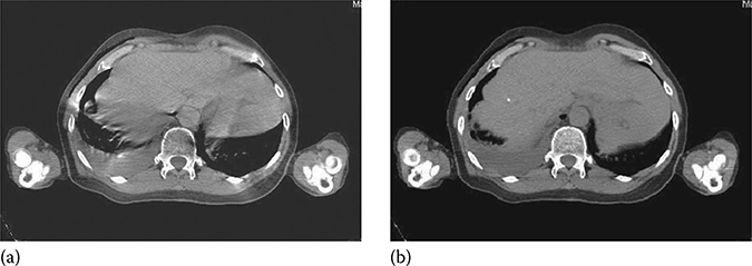
FIGURE 7.2
Slow-scan CT of the liver with a 4-s gantry rotation is in (a). The CT from averaging multiple phases of the cine CT images of 0.5-s gantry rotation over 4-s at the same location is in (b). The breath cycle of the patient was about 4 s. The artifacts in (a) were caused by the inconsistent projections from a 4-s gantry rotation, and were not present in (b). This indicated that a sub-second gantry rotation reduces the motion artifacts from reconstruction. (Reproduced from Pan T, et al., Med Phys, 33(10), 3931, 2006, Figure 11. With permission.)
Both Phillips and Siemens adopted a low-pitch helical CT scanning mode for their 4DCT design.6 This design was commercialized in 2006 on the MSCT scanners of at least 16 slices. In comparison, all the LightSpeed MSCT scanners of 4 slices and up, which have the cine CT scan capability that allows for a large coverage of the thorax in a simple protocol setup, are applicable for 4DCT. We will discuss the data sufficiency condition governing the 4DCT data collection; present the design of the commercial helical 4DCTs from Philips and Siemens; compare the differences between the helical 4DCT and the cine 4DCT in data acquisition, slice thickness, acquisition time, and work flow; review the respiratory monitoring devices in 4DCT; and understand the causes of image artifacts in 4DCT.
7.2 4DCT Data Acquisition
4DCT imaging needs to acquire data of a 3D volume for at least a complete breath cycle. A typical coverage is to cover the whole lungs. Since no CT detector is able to cover the whole lungs, and the conventional scan speed for diagnostic CT imaging is too fast to cover the whole lungs in a breath cycle, we need to slow down the scan speed for 4DCT imaging. Two scan modes can be utilized to achieve this goal: (1) cine CT scan and (2) low-pitch helical CT scan. Cine CT scan is a scan technique that acquires data at the same table position for more than one gantry rotation. Once the scan duration is set over one breath cycle, the need of 4DCT imaging can be achieved. Cine CT scan is similar to axial CT scan, except that the axial CT scan acquires data of either one gantry rotation for full scan reconstruction (FSR) or ½ of a gantry rotation cycle plus the fan angle of the detector for half-scan reconstruction (HSR).7 In short, cine scan acquires data of more than one gantry rotation and axial scan acquires data of less than or equal to one gantry rotation. For helical CT, we generally need to set the pitch factor to be 0.1 or less to achieve 4DCT imaging. Special care has to be taken to ensure the scanner parameters such as pitch factor, gantry rotation speed, table speed or table translation per rotation, and detector configuration are suitable for 4DCT imaging.
7.2.1 Data Sufficiency Condition (DSC)
To achieve 4DCT imaging of an object in the presence of respiratory motion, one must acquire data at each location for the duration of one breath cycle plus the duration for one image reconstruction. This is the data sufficiency condition (DSC) for 4DCT imaging.5 The time needed to acquire one image is equal to one gantry rotation cycle for FSR.7 Without loss of generality, we use FSR throughout the chapter. Additional data acquisition is needed because it takes one gantry rotation of data in CT for reconstruction of an image and to ensure that there are images at both ends of a complete breath cycle. This additional data acquisition is not necessary for projection x-ray imaging such as fluoroscopy in which each projection is an image by itself.8 Two acquisition modes of helical and cine can be used to realize the 4DCT imaging.
A helical CT scan acquires data when the table translates at a constant speed programmed by a pitch factor p, which is defined as the table travel per rotation divided by the width of the x-ray beam projected onto the rotation axis.
To satisfy the DSC with FSR, the pitch factors
where Tg and Tb are the durations of the gantry rotation cycle and the breath cycle, respectively. If the breath cycle Tb is the same as the gantry rotation cycle Tg, then after one Tg (e.g., Tb = Tg = 4 s), the detector moves in and out of the x-ray beam in exactly one Tb. Taking into account of the extra acquisition of Tg for one image reconstruction, p = ½. If the breath cycle Tb is four times of Tg (i.e., Tb = 4s, Tg = 1s), then p = 0.2. Typically, Tb = 4 s and Tg = 0.5 s and p = 0.11, similar to the typical pitch factor of 0.1 or less in the helical 4DCT in Tables 7.1 and 7.2.
One important observation of the pitch factor selection is that the longer the breath cycle Tb or the shorter the gantry rotation cycle Tg, the smaller the pitch factor p becomes. In diagnostic CT imaging with patient breath-hold and without gating, p is about 1, which is 10 times faster than in a helical 4DCT scan with respiratory gating!
It is straightforward to simply increase the scan time to achieve cine 4DCT imaging of each location for the duration of one breath cycle plus the duration for one image reconstruction. This design was in place on all GE LightSpeed multi-slice CTs before the cine 4DCT was developed in 2002.3 Only GE scanner has a user interface allowing the cine CT acquisition to be done with one scan statement. The user interfaces of Siemens and Phillips cannot be easily tailored for this purpose.4
TABLE 7.1
Pitch Factors p for the Philips CT Scanner and Calculated Values from Equation 7.1 at the Given Gantry Rotation Cycles Tg and Breath Cycles of 3–6s
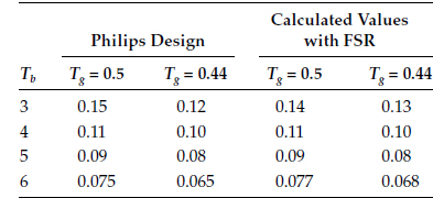
TABLE 7.2
Pitch Factors p for the Siemens CT Scanner and Calculated Values from Equation 7.1 at Given Gantry Rotation Cycles Tg and Breath Cycles of 3–6s

7.2.2 Data Acquisition Modes
An MSCT can be characterized by the number of data channels that can be simultaneously read (SR) in the patient table direction. This number of SR is also frequently referred to as the number of slices in MSCT. An MSCT with a higher number of SR typically means a newer MSCT that can scan the same coverage faster. To acquire the cine 4DCT data with the GE scanners, the numbers of SR data channels are 4, 8, 16, and 64. To acquire the helical 4DCT data with Siemens or Philips scanners, the numbers of SR data channels are 16, 20, 40, and 64. The reason that helical 4DCT starts at 16-slice was because Siemens/Philips only introduced the low-pitch helical CT scan (p ≤ 0.1) in their 16-slice and up CT scanners.
The number of physical data channels on an MSCT is at least the number of data channels of SR. Both GE's 4 and 8 channels have 16 physical detectors. For GE's 16 and 64 channels, there are 24 and 64, detectors, respectively. During data acquisition, the cine 4DCT utilizes the data acquisition modes of 4 × 2.5, 8 × 2.5, 8 × 2.5, and 16 × 2.5 mm on the GE's 4, 8, 16, and 64-slice CTs, respectively, to produce the images of slice thickness 2.5 mm (Figure 7.3a). In this case, a 16-slice CT may not have an advantage over an 8-slice CT in acquisition speed for the cine 4DCT because the detector size has reached 2 cm maximum for both the 8- and 16-slice GE CT.
In helical 4DCT data acquisition, the raw data before helical data interpolation are smaller than 1.5 mm. For the 16-slice, the mode of data acquisition is 16 × 1.5 mm. For the Siemens 20/40-slice, it is 20 × 1.2 mm. For the Philips 40/64-slice, it is 32 × 1.25 mm. Siemens 16, 20, and 40-slice CTs have the same detector size of 2.4 cm. Therefore, the speed of helical 4DCT is the same for the Siemens 16-, 20-, and 40-slice CTs. The Siemens 40- and 64-slice scanners use the z flying-focal spot to switch the focal spot between two positions to double-sample each angle of projection data to achieve the effect of 40 and 64-slice data even though their detector channels are 20 and 32, respectively.9 The detector size of 16, 20, and 40-slice Siemens CTs is 2.4 cm, and it is 2.88 cm for the 64-slice Siemens CT. The Philips 40 and 64-slice CTs have 4-cm detector coverage, and their data acquisition is 32 × 1.25 mm for the helical 4DCT, which will shorten the acquisition time for a large coverage. It is important to note that slice broadening of 180% in the low-pitch helical 4DCT prevents the smallest data element in data acquisition from greater than 1.5 mm.5
7.2.3 Image location, Slice Thickness, and Scan Time
Helical 4DCT scan data allow for CT image reconstruction at any location by permitting data interpolation between two neighboring detector elements, whereas cine 4DCT scan data allow for reconstructions only at the scan position.
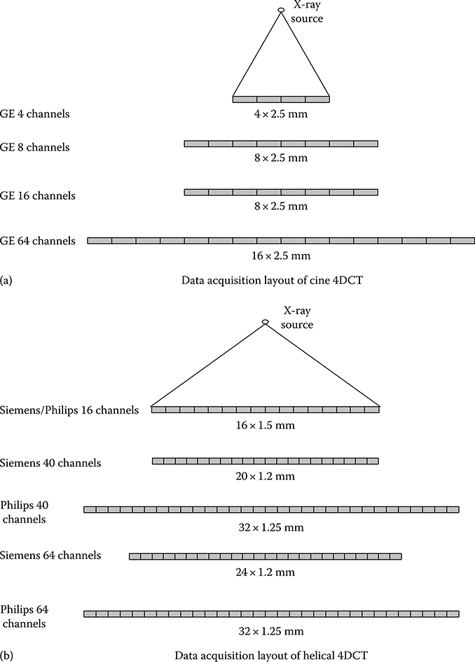
FIGURE 7.3
(a) GE detector layout for 4, 8, 16, and 64 data channels. The speed of cine 4DCT acquisitions is the same for both 8 and 16 data channels, which utilizes the maximum of 2-cm (8 × 2.5 mm) detector coverage. (b) Data acquisition layout of Siemens/Philips helical 4DCT for various data channels. The detector coverage of 4 cm is the same for the Philips 40 and 64 channels. The detector coverage of 2.4 cm is the same for the Siemens 16, 20, and 40 channels.
When using 4DCT to scan patients with lung cancer, it is important to have a complete coverage of the lungs for tumor delineation and dose calculation. The flexibility of image reconstruction at any location is not important if the images of evenly spaced slices can be reconstructed to create a 4D volume. Typical image slice thicknesses in radiation treatment planning are 2–3 mm. There is a penalty for data interpolation in helical 4DCT as it widens the slice sensitivity profile, a measure of the slice thickness of the CT image. It is important to use thin slice collimation of 16 × 1.50 mm in helical 4DCT on a 16-slice MSCT scanner because data interpolation will widen a slice thickness of 1.50 mm to almost 2.7 mm (i.e., the 1.5-mm slice will be thickened to 1.8 times of its original width). Similarly, this means that if the detector configuration is 8 × 2.50 mm, the slice thickness will become 4.5 mm in helical 4DCT. Same 8 × 2.50 mm collimation in cine 4DCT will generate the slices of 2.5 mm because no data interpolation is in the cine CT image reconstruction. In diagnostic imaging, data interpolation causes only about 20% widening when the pitch is greater than 0.5; the amount of widening reaches 180% when the pitch factor is less than 0.2.5 To better understand this, we can take two independent slices of 2.5 mm at two neighboring locations in cine 4DCT and interpolate between them for an image located equi-distance to the two slices; in such a case, interpolation would assign 50% weight to each image, and the composite image will become a 5.0-mm slice (resulting in 200% broadening of the slice thickness). Image reconstruction at pitch factors of less than 0.1 in helical 4DCT significantly thickens the CT images. Once the pitch factor p becomes 0, helical CT interpolation is no longer needed and helical 4DCT becomes cine 4DCT. That is the reason that the typical detector configuration for a 16-slice MSCT is 16 × 1.50 mm to keep the slice thickness <3 mm.
There is one additional breath cycle of acquisition time needed for the same coverage in helical 4DCT than in cine 4DCT. Scan of over half of a breath cycle time before the starting position and scan of after half of a breath cycle time after the end location to ensure each location has a complete breath cycle of data. Since the 4DCT acquisition for the lung cancer patient typically covers the whole lung, this additional acquisition of one breath cycle in the helical 4DCT is not significant when the number of breath cycles in a 4DCT is likely between 30 and 40 breath cycles. It contributes to a small amount of extra time for acquisition and a small amount of extra radiation exposure to the patient. Overall, helical 4DCT is faster than cine 4DCT because in cine 4DCT the table is paused to allow the table to move from one position to the next position; the accumulated pause time lengthens the overall acquisition time required for cine 4DCT, making helical 4DCT for the breath cycles of >6 s a faster 4DCT. The speedup (in favor of helical 4DCT) and extra radiation (in favor of cine 4DCT) are both very small.
7.2.4 Work Flow and Phase Selection Accuracy
The clinical work flow of helical 4DCT is that once the pitch factor is determined on the basis of either Table 7.1 or 7.2, collections of the helical 4DCT data and the respiratory signal have to proceed simultaneously. Reconstruction of the helical 4DCT images will not start until completion of the scan and after the respiratory signal is examined for accuracy in identification of the end-inspiration phases. This process allows for the reconstruction of 4DCT images at the specified phases in the helical 4DCT scan. Helical 4DCT tends to be slower than cine 4DCT in processing because the reconstruction is performed after (1) completion of the low-pitch helical CT scan and (2) verifi-cation of the end-inspiration phases in the respiratory signal. A suggestion to start image reconstruction before completion of data acquisition is possible. However, any change of image selection will likely result in additional image reconstruction. Because of these factors, multiple phases of helical 4DCT may not be available several minutes after the patient leaves the 4DCT acquisition session.
The clinical work flow of step and shoot cine 4DCT is that data processing is generally faster for cine 4DCT than helical 4DCT to generate the 4DCT images. Once the average duration of the respiratory signal has been determined, the cine scan duration per location is set to the average duration plus 1 s. This additional 1 s is recommended in case the patient's breath cycle becomes longer during data acquisition. Image reconstruction starts immediately when there is enough data for one image to be reconstructed. The time interval between two CT image reconstructions should be less than Tg.
For example, if Tg = 0.5 s, then the interval can be set at 0.25 s for 50% data sharing between two image reconstructions to generate more images for data correlation with the respiratory signal, whose end-inspiration phases can be checked independently from the cine CT data collection. Increase of data sharing is to increase data sampling in cine 4DCT for data correlation so that the image selection will have a better chance of getting the images at the targeted phases. Because image reconstruction is performed independently from acquisition of the respiratory signal, more accurate correlation of the CT images to a particular phase of the breathing cycle is possible when two successive image reconstructions share more data or the time interval between two images is much shorter than Tg.
In general, phase selection accuracy is better with helical 4DCT than with cine 4DCT because the reconstruction of a particular phase is determined before image reconstruction in helical 4DCT, but not in cine 4DCT. For a long respiratory cycle of greater than 5 s, helical 4DCT may result in fewer sampling of the 4DCT images than cine 4DCT would and therefore may not fully capture the extent of tumor motion depicted in the maximum intensity projection images.3 It is advisable to increase the number of phases in image reconstruction in helical 4DCT to improve the inclusion of the tumor motion so that the full extent of tumor motion will be included.
One important quality control measure that must be undertaken in 4DCT is to ensure that identification of the end-inspiration phases by the respiratory monitoring device is accurate. If phase calculation or identification is not accurate, both helical and cine 4DCTs will generate erroneous data, not representative of the 4DCT data. One example of this is illustrated in Figure 7.4. Some end-inspiration phases in (a) were incorrectly identified or missing. The correct identification of the phases is shown in (b). This step of ensuring accurate identification of end-inspiration phases is critical and should be checked in every 4DCT data processing.
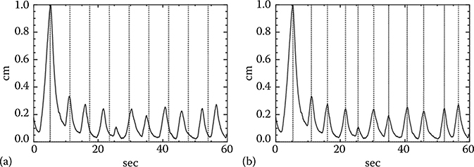
FIGURE 7.4
(a) An example of a respiratory signal over 60 s after a very irregular respiratory cycle causing an inaccurate identification of the end-inspiration phases, marked by dotted vertical lines. (b) Shows the accurate identification of the end-inspiration phases.
7.2.5 Commercial Helical 4DCT Systems
Philips and Siemens offer helical 4DCT. Both implementations were derived from the low-pitch helical CT scan of cardiac CT, which has pitch factors p of 0.2–0.3 for a targeted heart rate of about 60 beats per minute. By lowering p to 0.1 or less, and replacing the electrocardiographic monitor with a respiratory monitor, the helical 4DCT for imaging the thorax under the condition of respiratory motion of 10–20 cycles per minute (corresponding to a 3- to 6-s respiratory cycle) becomes possible. The slower the respiratory motion, the smaller the pitch factor p has to be to meet the DSC and to avoid undersam-pling in helical 4DCT. An example of undersampling is shown in Figure 7.1c.
The pitch factors p of the Philips CT scanners10 and calculated factors by Equation 7.1 for the breathing cycles of 3–6 s and gantry rotations of 0.44 and 0.5 s for FSR are listed in Table 7.1. Both factors match closely. When the gantry rotation time changes from 0.5 to 0.44 s, pitch factors p become smaller because the shorter gantry rotation time allows the scanner to cover a larger volume for the same duration at the same pitch, which may cause the scanner to scan too fast and violate the data sufficiency condition. Equation 7.1 can be used to calculate the gantry rotation cycles and the breath cycle durations other than those listed in Table 7.1.
The Siemens pitch factors11 and calculated factors from Equation 7.1 are listed in Table 7.2. This scanner uses a single pitch factor of 0.1 and 2 gantry rotation cycles of 0.5 and 1.0 s.12 Since the pitch factors p stay the same, the gantry rotation time has to be increased with the duration of the breath cycle. This design is different from that of the Philips CT scanner, whose pitch factor becomes smaller when the breath cycle becomes longer. In the Siemens design, a longer gantry rotation cycle of 1.0 s is required to slow down the scan speed to accommodate for a breath cycle of ≥6 s with the same p of 0.1. One disadvantage in this design is that each CT image will have a temporal resolution of 1 s for FSR and 0.5 s for HSR. Longer breath cycles tend to have a longer duration of expiration than shorter cycles do. A decrease of the temporal resolution will increase image blurring in the CT image, particularly for the images acquired in the transition of the end-expiration phase to the end-inspiration phase, which tends to have the largest motion during respiration.
7.2.6 Respiratory Monitoring Devices
4DCT needs the timing information of the end-inspiration phase to guide its image reconstruction in helical 4DCT or image correlation in cine 4DCT. Many respiratory monitoring devices have been suggested.8 The phase range between two end-inspiration phases is 100%, and the phase linearly increases from one end-inspiration phase to the next end-inspiration phase. Spirometer was used to measure the lung volume in inhale and exhale for the respiratory signal to correlate with the cine CT images for 4DCT.4 The spirometer measurement is highly dependent on patient cooperation and may not be reproducible.
The most popular device for recording and monitoring the respiratory signal in 4DCT is the Real-time Position Management (RPM) respiratory gating system (Varian Medical Systems, Palo Alto, CA) shown in Figure 7.5a. The system consists of multiple infrared emitting diodes, an infrared camera, a plastic box with two or six infrared reflective markers, and the optical tracing software and computer. The infrared emitting diodes are mounted on the camera, which receive the reflected infrared signal from the reflective markers on a plastic box sitting on top of the patient's abdomen between the umbilicus and xiphoid process. The RPM device can measure the patient's respiratory pattern and range of motion and displays them as a waveform. It can also send out triggers to enable prospective gating of CT. The plastic box, which is the only thing touching the patient, is almost radiation translucent, and the RPM can be integrated with some linear accelerators which use the device to turn the treatment beam on and off when the patient's breathing amplitude falls into the range of treatment. However, if the patient's abdomen or chest does not have a flat surface to allow the plastic box to sit on, placing the plastic box to the camera at the right angle may not be straightforward. The RPM system has been integrated in the GE and Philips 4DCTs.

FIGURE 7.5
Respiratory monitoring devices used in 4DCT. (a) Two reflective markers on a plastic box and an infrared camera from Varian; (b) a pressure sensor from Anzai; and (c) air bellow (also a pressure sensor) from Philips.
Another device is the AZ-733V pressure sensor device (Anzai Medical Corporation, Tokyo, Japan) for recording the respiratory signal, respiratory gating and triggering. The system is comprised of chest/abdominal belt, pressure transducer (Figure 7.5b), sensor port, Wave Deck (signal processing box), laptop PC with connecting cables, and a trolley cart for storage and transport of the system. The pressure sensor can be easily attached to a patient with a Velcro belt. Measurement of the breathing signal is relative because the output of the pressure sensor is dependent on the tightness the Velcro belt fastened around the patient's chest or abdomen. One disadvantage of this system is that the sensor is radiopaque and can induce metallic artifacts. Placement of the sensor outside of the treatment field can avoid the metallic artifacts. The AZ-733V system is integrated in the Siemens 4DCT. It has been shown that there is a high correlation between the AZ-733V and RPM.13
A third device also used in 4DCT is the air bellow (Figure 7.5c), which is an elastic belt positioned around the abdomen that expands and contracts with the respiratory motion.14 The device contains a pressure transducer, which converts the pressure waveform to a voltage signal, which is then digitalized and transmitted to the CT scanner. Using a respiratory bellow to monitor the breathing state has also been applied to CT-guided intervention procedure and MR imaging.
7.2.7 Image Artifacts
The basic assumption of 4DCT is that the respiratory motion is reproducible throughout the data acquisition and the duration of data acquisition at any location is at least one breath cycle plus the duration for one image reconstruction, which is one or 2/3 of a CT gantry rotation. Anything deviating from this assumption can induce artifacts manifested as (1) irregular respiratory motion, (2) misregistration at the cardiac region as the heart beating is not taken into account in 4DCT, and (3) missing data if the scan at a location is less than one breath cycle due to an underestimate of the patient's breath cycle duration. As a result, a higher helical pitch p in the Philips helical 4D or a faster CT gantry rotation in the Siemens helical 4D, or a shorter cine scan duration in GE cine 4D could introduce artifacts.15 Figure 7.6 shows an example of these three types of artifact.
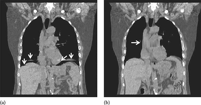
FIGURE 7.6
4DCT artifacts (pointed by arrows) due to (a) irregular respiration and misregistration in the cardiac region, not accounted for in 4DCT and (b) undersampling in a prolonged breathing cycle.
7.2.8 Average CT (ACT) and Maximum Intensity Projection (MIP) CT
ACT can be derived from averaging the 4DCT images or the cine CT images of many phases.16,17 The conventional approach with slow-scan CT for ACT is incorrect and should be discouraged.2,16 Figure 7.2 shows a clinic example of the same patient scanned with a slow-scan CT of 4 s and ACT of fast gantry rotation of 0.5 s. Cine-CT and low-pitch helical CT (pitch < 0.1) scans can be used to obtain ACT and both have been utilized in 4D CT imaging. ACT has been shown to be effective in dose calculation and registration with the PET data.16,17
MIP CT images can be derived by finding the maximum pixel value at each pixel from all the phases of 4DCT or cine CT images.18 It has been shown that MIP CT images are effective in depicting the extent of tumor motion.19,20 Figure 7.7 shows an example of MIP and ACT images. Both MIP and ACT images can be derived without gating.16,18
7.2.9 Conclusions and Future Directions
4DCT was an important development for imaging the tumors subject to the respiratory motion for radiation therapy. Its development was very closely tied to the MSCT technology, commercialized in 1998. Helical 4DCT was adopted by Siemens and Philips and commercialized in 2006, and cine 4DCT was developed by GE and commercialized in 2003. Both helical and cine 4DCT scans need to meet the requirement of data sufficiency condition to ensure there is at least one respiratory cycle of data at each location. Unlike cine 4DCT, helical 4DCT tends to result in thicker slices due to data interpolation and a longer work flow because image reconstruction cannot start until the respiratory signal of the helical 4DCT scan has been completely acquired. Commercial helical 4DCT can be performed by MSCT scanners of 16-slice or up, while cine 4DCT can be done using MSCT scanners with 4-slice or up. Three popular respiratory recording and monitoring devices are the optical device of RPM from Varian, the pressure sensor from Anzai, and the air bellow pressure sensor from Philips. To ensure a complete depiction of tumor motion, one should obtain at least 10 phases of 4DCT images in helical 4DCT, in particular for patients with the breath cycle duration of ≥6 s. The average and MIP CT images are important for registration with the PET data and tumor delineation, respectively. A very important quality control step in 4DCT is to ensure accuracy in identifying the end-inspiration phases of the respiratory signal because inaccurate identification of the end-inspiration phases will cause 4DCT to generate incorrect data. For the future development, the capability of 4DCT to cope with the irregular respiration is critical. However, it may not be possible to demand an artifact-free 4DCT due to irregular respiration when 4DCT is applied on the patient population with the lung disease which manifests itself as coughing and/or irregular respiration.
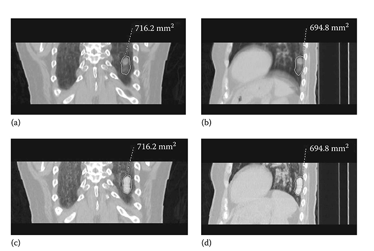
FIGURE 7.7
(a) and (b) are average CT images, (c) and (d) are the corresponding MIP CT images from the cine CT images of a patient for 4DCT. The 2D ROIs were derived from the MIP CT images.
References
1. Underberg R.W., Lagerwaard F.J., Cuijpers J.P., Slotman B.J., van Sornsen de Koste J.R., Senan S. Four-dimensional CT scans for treatment planning in stereotac-tic radiotherapy for stage I lung cancer. Int J Radiat Oncol Biol Phys. Nov 15 2004;60(4):1283–1290.
2. Keall P.J., Mageras G.S., Balter J.M., The management of respiratory motion in radiation oncology report of AAPM Task Group 76. Med Phys. Oct 2006;33(10):3874–3900.
3. Pan T., Lee T.Y., Rietzel E., Chen G.T.. 4D-CT imaging of a volume influenced by respiratory motion on multi-slice CT. Med Phys. Feb 2004;31(2):333–340.
4. Low D.A., Nystrom M., Kalinin E., A method for the reconstruction of four-dimensional synchronized CT scans acquired during free breathing. Med Phys. Jun 2003;30(6):1254–1263.
5. Pan T. Comparison of helical and cine acquisitions for 4D-CT imaging with mul-tislice CT. Med Phys. Feb 2005;32(2):627–634.
6. Keall P.J., Starkschall G., Shukla H., Acquiring 4D thoracic CT scans using a multislice helical method. Phys Med Biol. May 21 2004;49(10):2053–2067.
7. Parker D.L.. Optimal short scan convolution reconstruction for fanbeam CT. Med Phys. Mar–Apr 1982;9(2):254–257.
8. Kubo H.D., Hill B.C.. Respiration gated radiotherapy treatment: a technical study. Phys Med Biol. Jan 1996;41(1):83–91.
9. Flohr T.G., Stierstorfer K., Ulzheimer S., Bruder H., Primak A.N., McCollough C.H.. Image reconstruction and image quality evaluation for a 64-slice CT scanner with z-flying focal spot. Med Phys. Aug 2005;32(8):2536–2547.
10. 10. Quick Steps for Retrospective Spiral Respiratory Correlated Imaging with Varian RPM. for the Brilliance CT Big Bore v2.2.2 system and the Brilliance 16–64 v2.2.5. 2007. Philips CT Product Oncology Application (453567455491).
11. Somatom Sensation Open Reference Manual. 159–177.
12. Hurkmans C.W., van Lieshout M., Schuring D., Quality assurance of 4D-CT scan techniques in multicenter phase III trial of surgery versus stereotac-tic radiotherapy (radiosurgery or surgery for operable early stage (stage 1A) non-small-cell lung cancer [ROSEL] study). Int J Radiat Oncol Biol Phys. Jul 1 2011;80(3):918–927.
13. Li X.A., Stepaniak C., Gore E. Technical and dosimetric aspects of respiratory gating using a pressure-sensor motion monitoring system. Med Phys. Jan 2006;33(1):145–154.
14. Klahr P., Subramanian P., Yanof J.H.. Respiratory-correlated multislice CT for radiation therapy planning: imaging and visualization methods. Medicamundi. 2005;49(3):34–37.
15. Han D., Bayouth J., Bhatia S., Sonka M., Wu X. Characterization and identification of spatial artifacts during 4D-CT imaging. Med Phys. Apr 2011;38(4):2074–2087.
16. Pan T., Mawlawi O., Luo D., Attenuation correction of PET cardiac data with low-dose average CT in PET/CT. Med Phys. Oct 2006;33(10):3931–3938.
17. Pan T., Mawlawi O., Nehmeh S.A., Attenuation correction of PET images with respiration-averaged CT images in PET/CT. J Nucl Med. Sep 2005;46(9):1481–1487.
18. Pan T., Sun X., Luo D.. Improvement of the cine-CT based 4D-CT imaging. Med Phys. Nov 2007;34(11):4499–4503.
19. Underberg R.W., Lagerwaard F.J., Slotman B.J., Cuijpers J.P., Senan S. Use of maximum intensity projections (MIP) for target volume generation in 4DCT scans for lung cancer. Int J Radiat Oncol Biol Phys. Sep 1 2005;63(1):253–260.
20. Bradley J.D., Nofal A.N., El Naqa IM, Comparison of helical, maximum intensity projection (MIP), and averaged intensity (AI) 4D CT imaging for stereotac-tic body radiation therapy (SBRT) planning in lung cancer. Radiother Oncol. Dec 2006;81(3):264–268.