Chapter Goal: Review how basic shapes are created with the Pen and Shape tools and how they can be distorted with the Direct Selection tool or scaled or rounded using bounding box handles and guides.
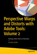
Toolbars panels for Pen tools, Shape tools, and Selection tools
You can find the projects for this chapter in the Chapter 2 folder.
Let’s start with a review of the Pen tools.
In this chapter and the rest of the book, when I refer to shapes and paths collectively, I will use the word “object.”
Pen Tools and Curvature Tool
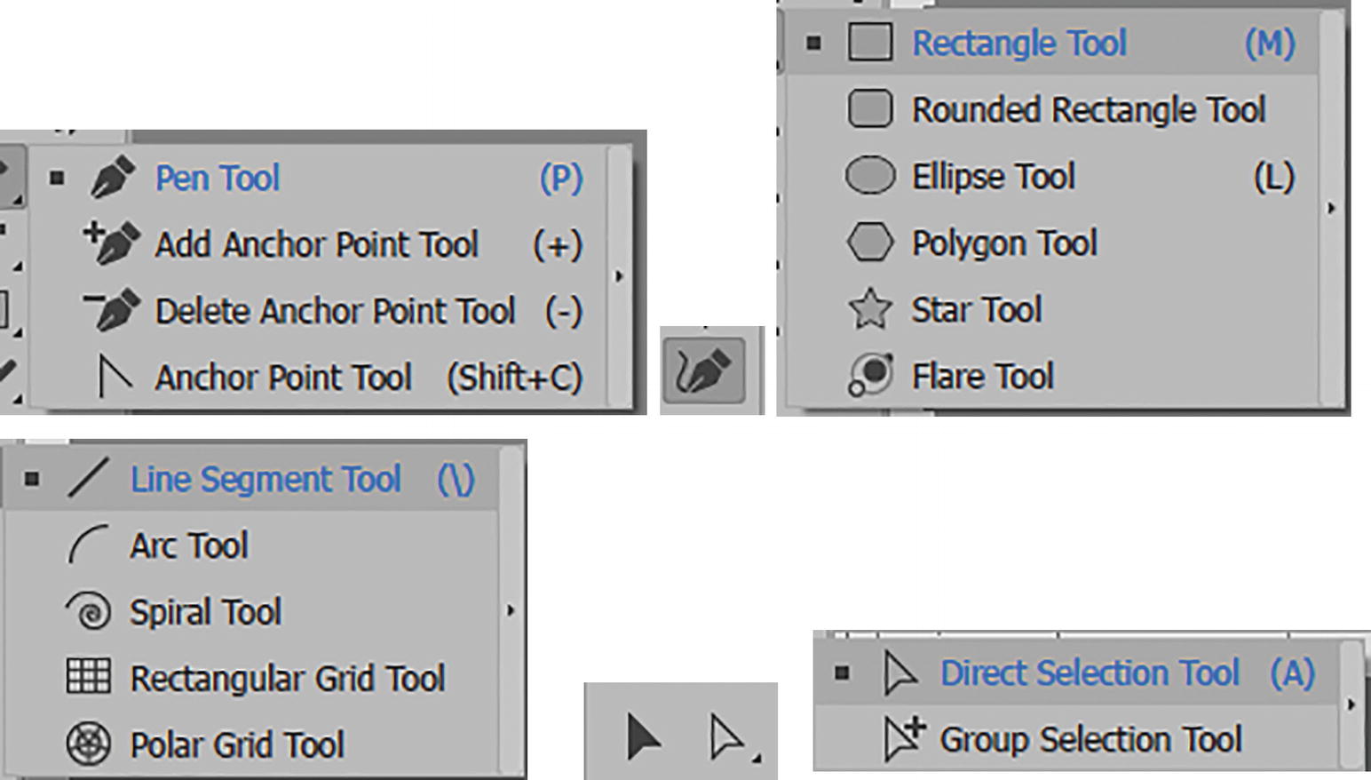
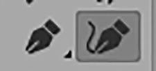
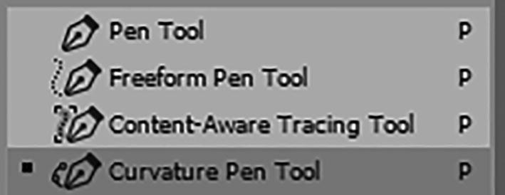
Some of Photoshop’s Pen tools

Pen tools in Illustrator
Pen Tool (P) Review
To start our review of the tools, open your file that you started in Chapter 1 if you want to practice, or create a new blank document using the steps mentioned in Chapter 1. You could also open the file pen_shape_practice.ai, which is an empty document, to practice with; it’s located in the Chapter 2 folder.
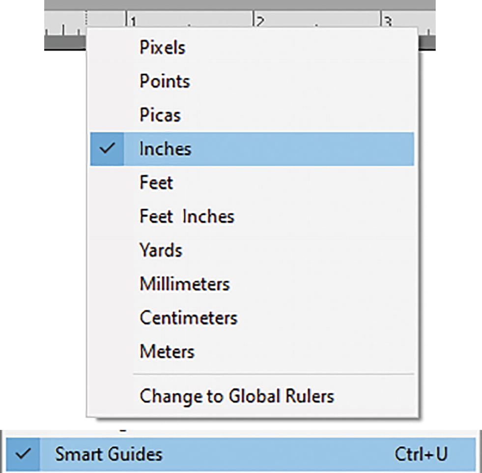
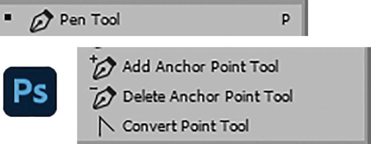
Setting the ruler measurement increments to inches for the Artboard and enabling the Smart Guides in the view menu
I also have my Smart Guides enabled. Go to View ➤ Smart Guides (Ctrl/CMD+U). Refer to Figure 2-4.
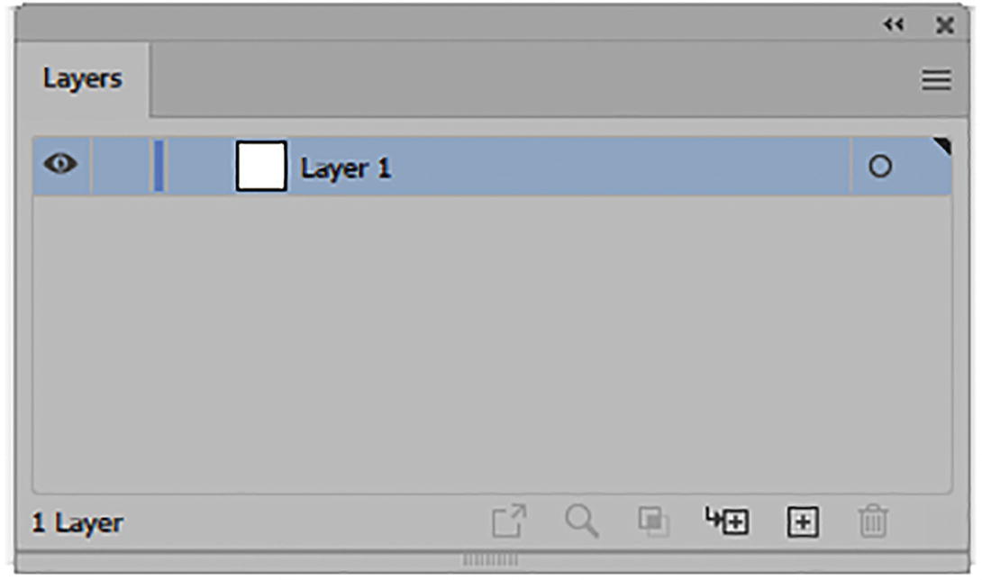
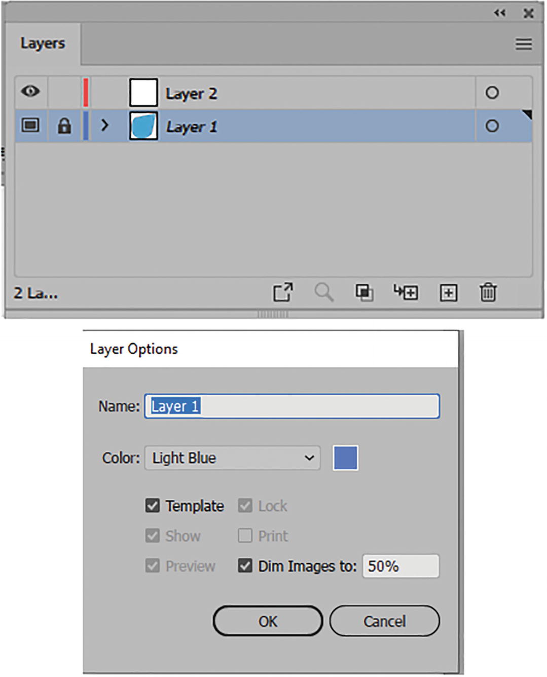
Layers panel with Layer 1 selected
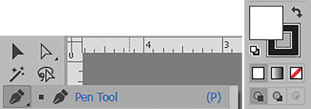
Pen tool with fill set to default white and stroke to black
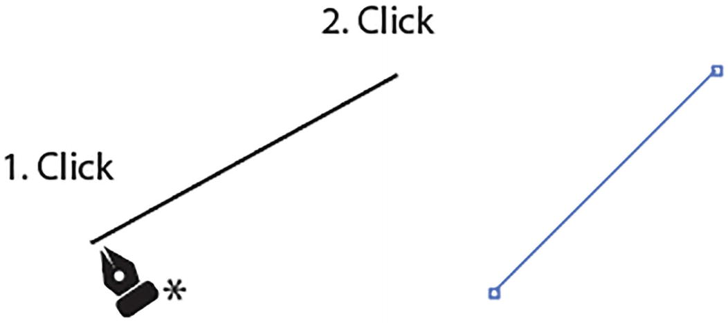
Use the Pen tool to create a path
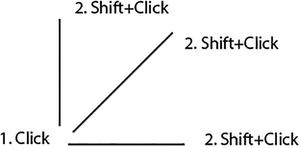
Use the Pen tool with the Shift key to create a straight path
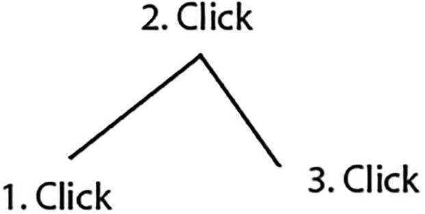
Use the Pen tool to create more points on the path
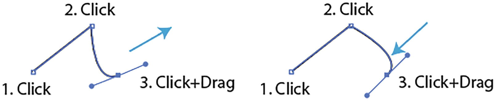
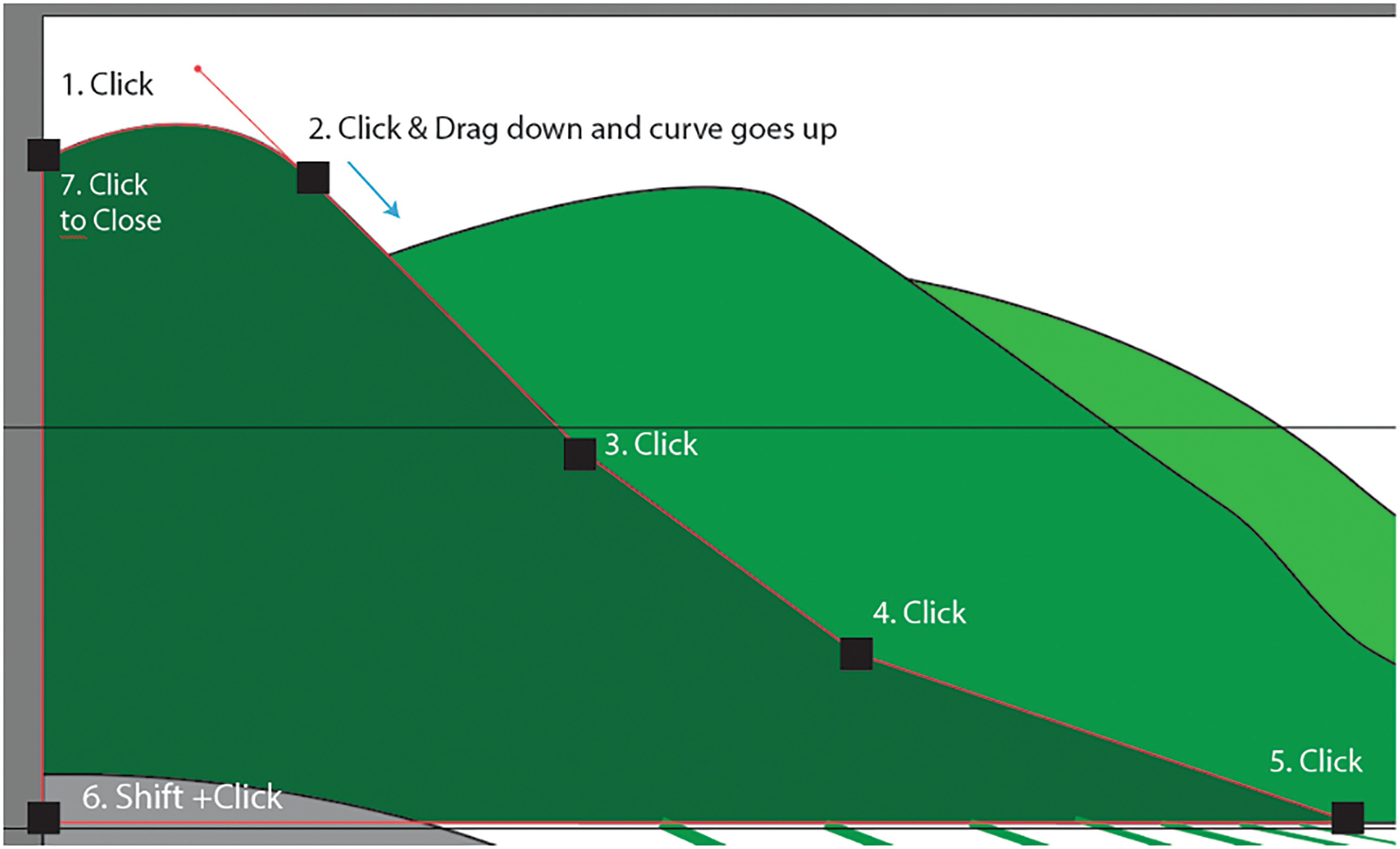
Use the Pen tool to create a path with a curve
Use the Pen tool to add more points to the path after creating a curve
Use the Pen tool to add more points to the path after creating a curve, and curve again
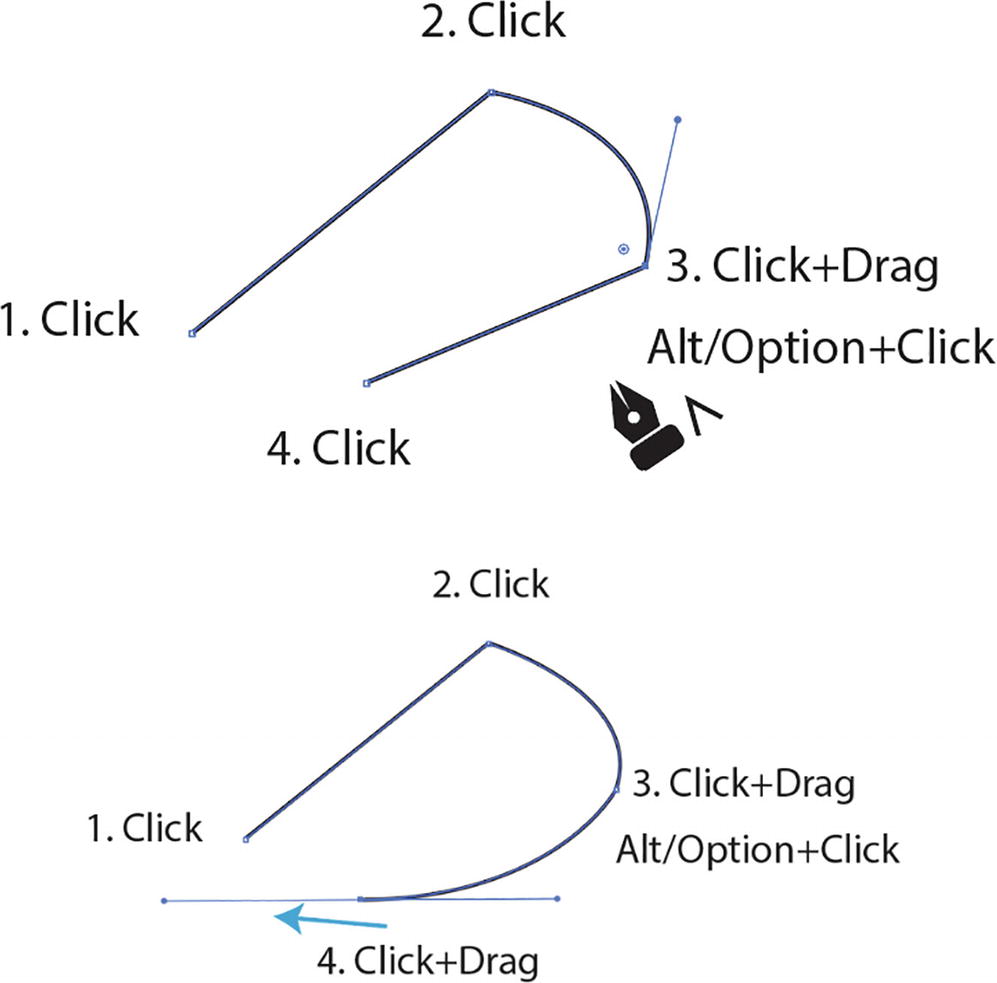
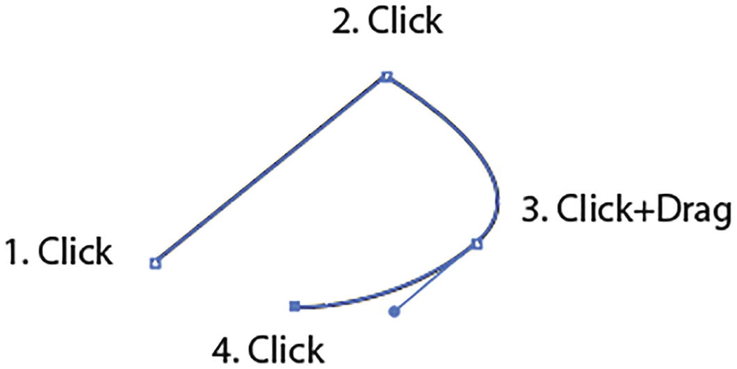
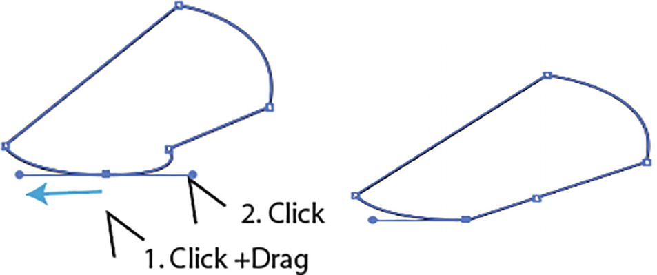
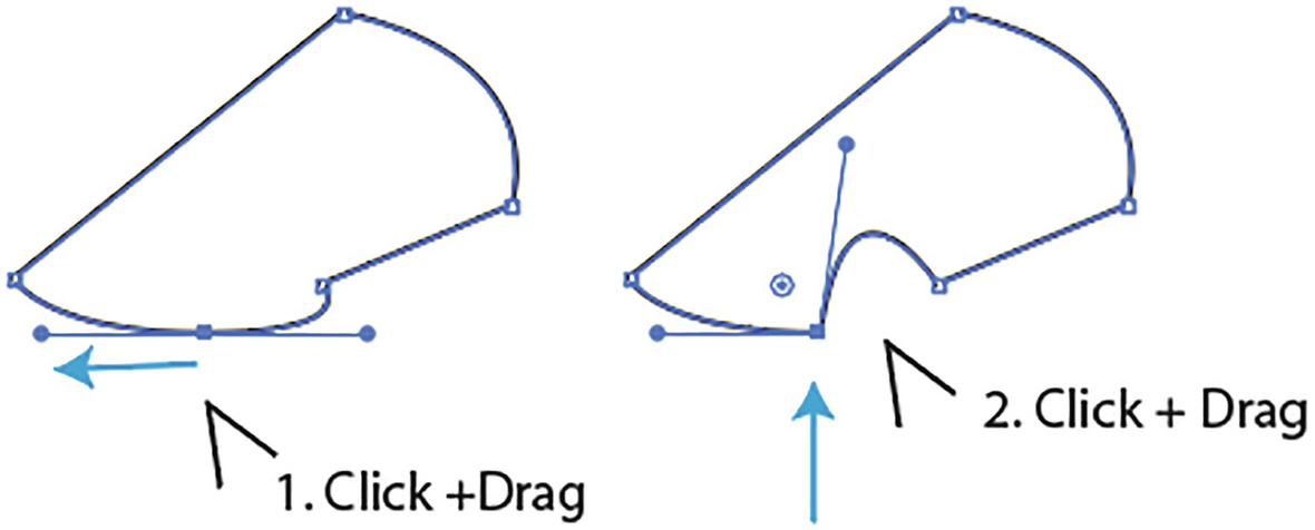
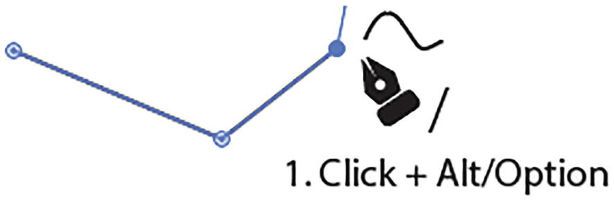
Use the Pen tool to change a curved line back to a straight corner with Alt/Option + Click, or curve the line on the next click and drag
Or you can click and drag for point 4 to create a curve again. Refer to Figure 2-13.
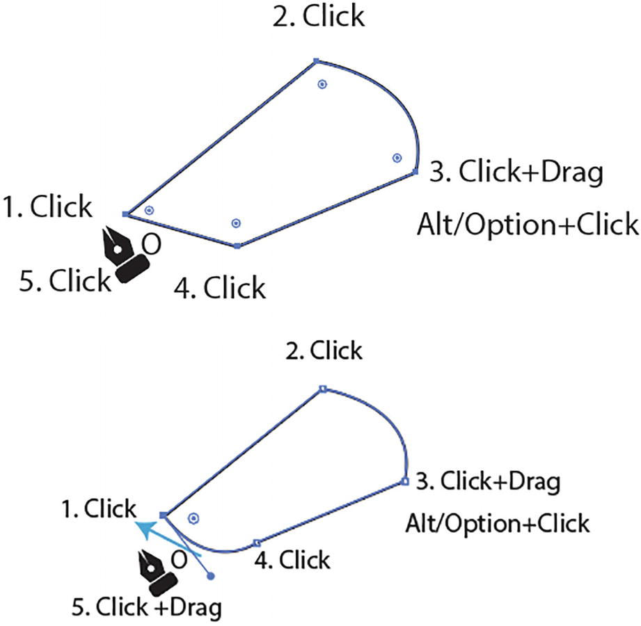
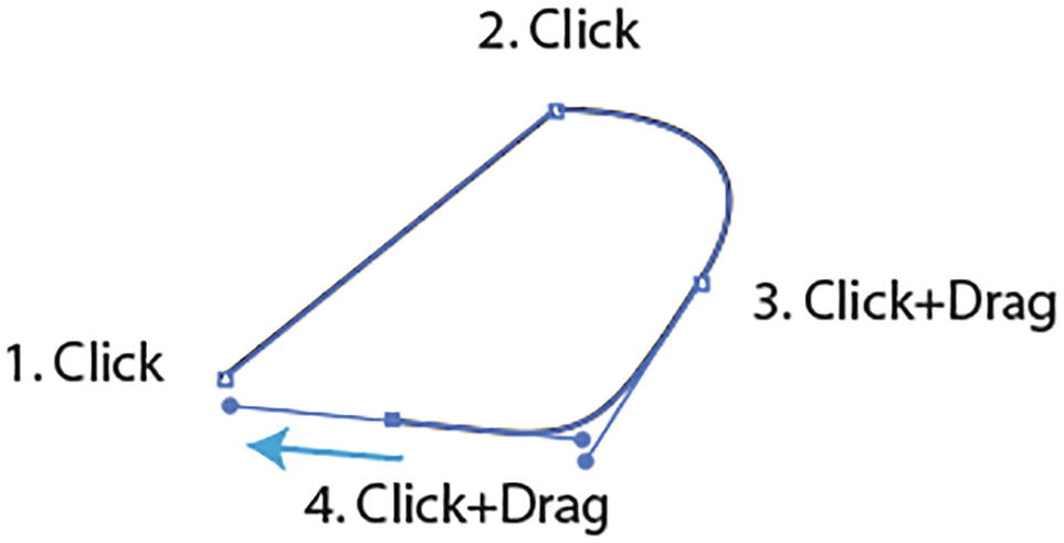
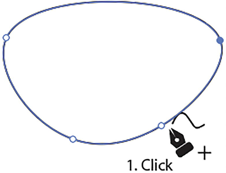
Close the path as either a straight or a curved path with the Pen tool
Or click and drag to close the path with a curve. Then, release the mouse button, and you should have a closed path. Refer to Figure 2-14.
Adding the Shift key while you click and drag can also assist in your path adjustment.
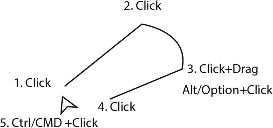
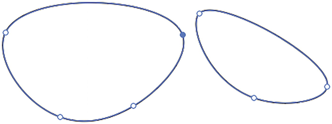
Leave the path open using the Pen tool when you Ctrl/CMD + Click
Join Points on an Open Path
Join two points for a closed path or connect two open paths with the Pen tool
Or if you are joining two open paths but not closing a path, you will see a pen cursor icon connection point between the two points. Refer to Figure 2-16.
Use the Zoom key commands (Ctrl/CMD ++ and Ctrl/CMD+ -) and Hand tool (spacebar) when you need to navigate while using the Pen tool so you don’t deselect the path while you work.
Add Anchor Point Tool (+) Review
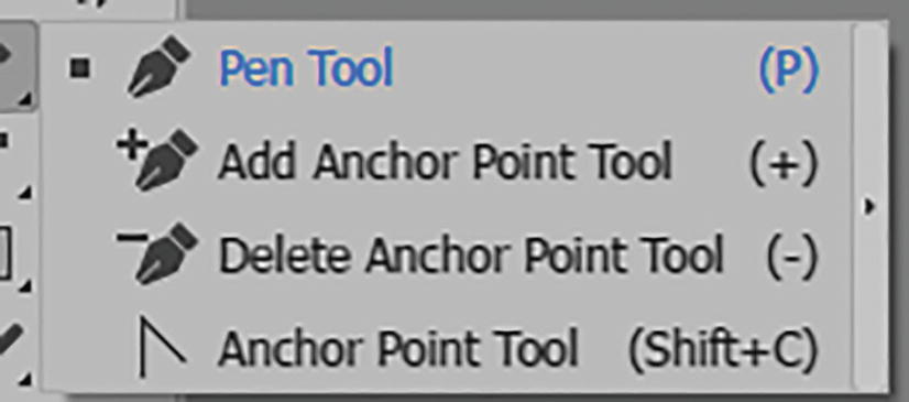
Toolbars panel Add Anchor Point tool
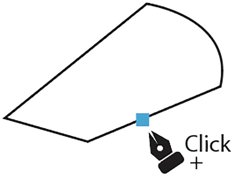
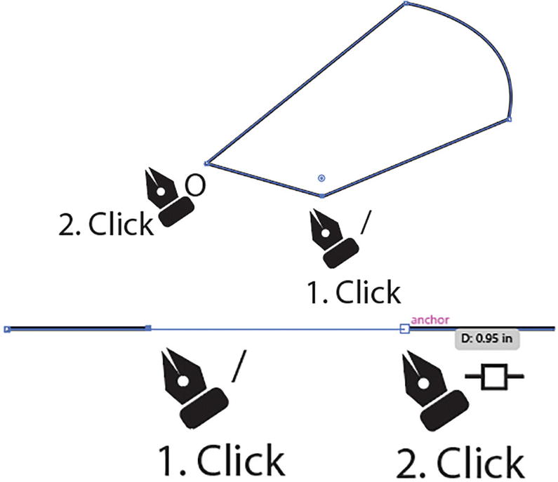
Add a point with the Add Anchor Point tool
If you do not want to switch tools, you can also use the Pen tool and hover over part of a selected path with the pen cursor until a plus symbol is added, then just click to add a point. We will look at how to select paths in the next section.
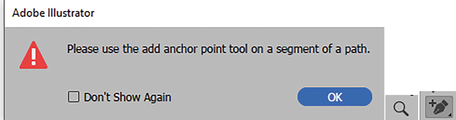
When you click on another point with the Add Anchor Point tool, you will get a warning message to add the point to a segment of a path
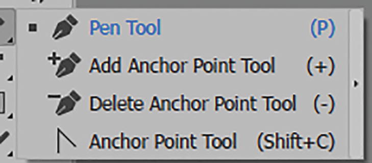
Delete Anchor Point Tool (-) Review
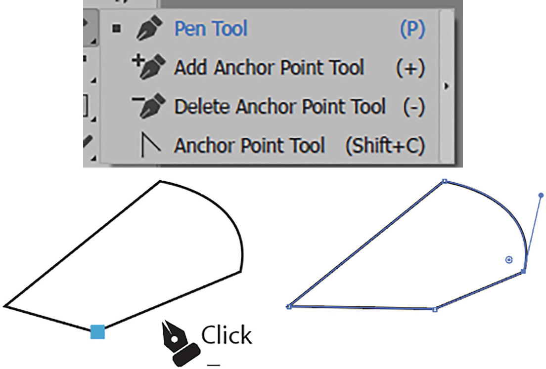
Toolbars panel Delete Anchor Point tool. Click on a point to delete the point
If you do not want to switch tools you can also use the Pen tool and hover over a selected point with the pen cursor until a minus symbol is added, then just click to remove the point. We will look at how to select paths in the next section.
Hold down the Alt/Option key when you want to switch between the Add Anchor Point tool and Delete Anchor Point tool while either tool is in use.
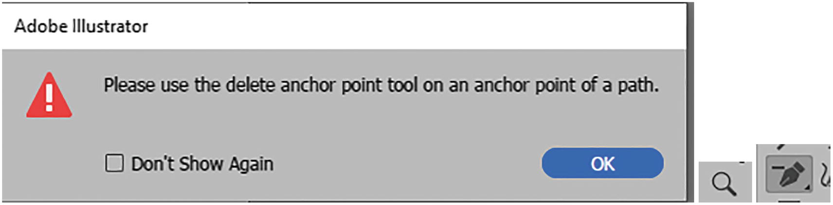
When you click on a path with the Delete Anchor Point tool, you will get a warning message to use the tool on an anchor point of a path
Anchor Point Tool (Shift +C) Review
Toolbars panel, Anchor Point tool
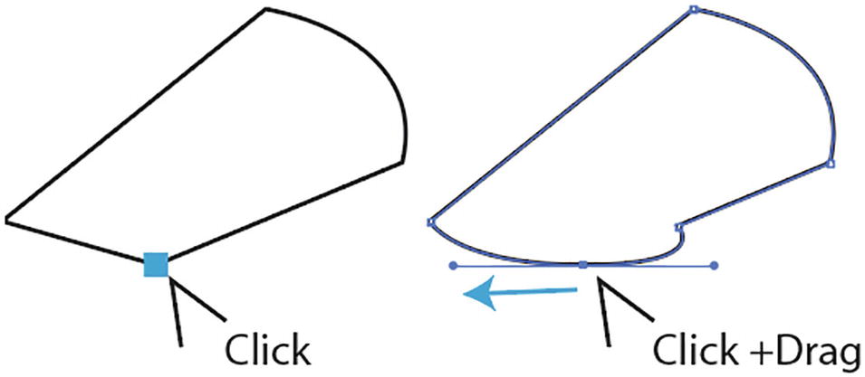
Convert a point from corner to curved with the Anchor Point tool
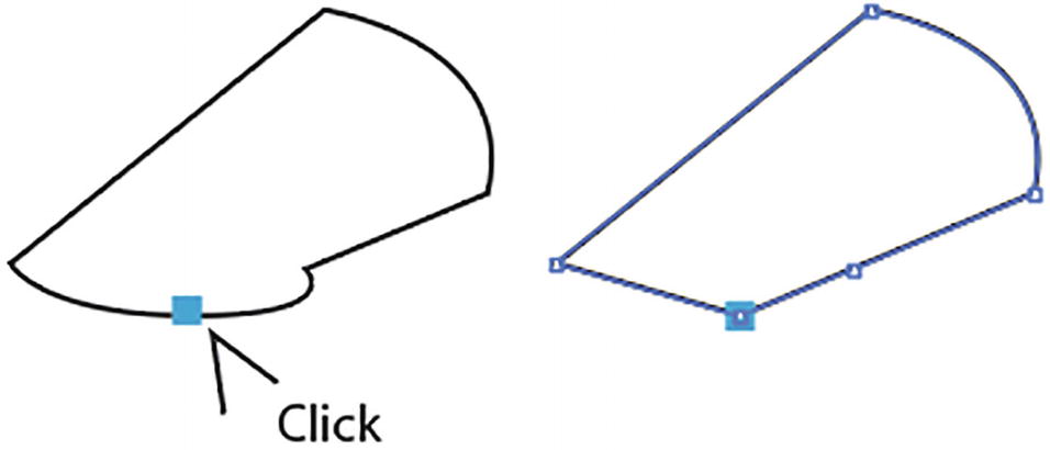
Convert a point from curved to corner with the Anchor Point tool
Create a point that is both curved and corner with the Anchor Point tool
Create a point that changes the path’s direction with the Anchor Point tool
Adjust the path with the Anchor Point tool
The Anchor Point tool is good for untangling twisted points as well that you may have created while using the Pen tool. Click and drag in the opposite direction to untangle. Refer to Figure 2-28.
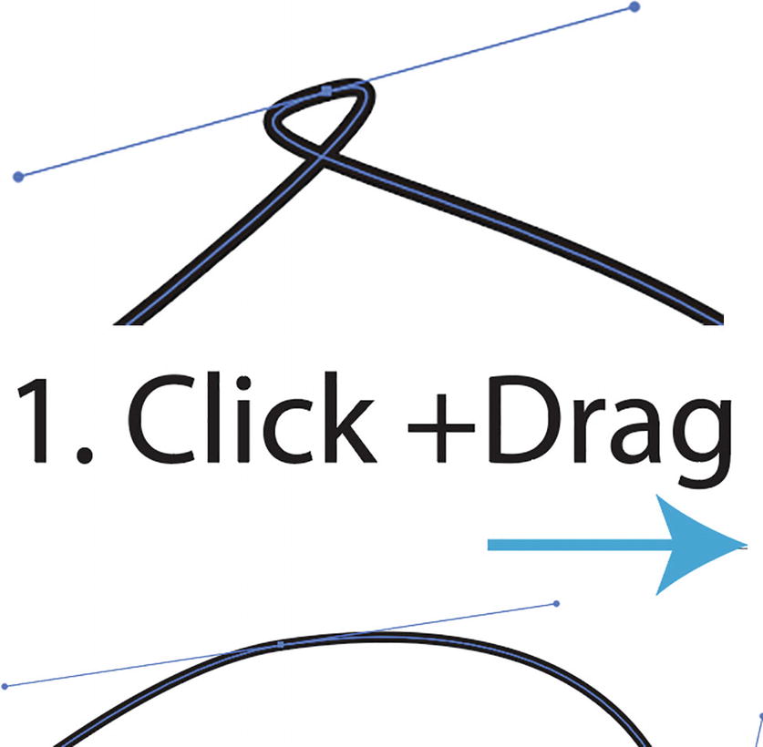
Untangle a path with the Anchor Point tool
Remember you can always go back to Photoshop and apply what you learned here about the Pen tool to your own Photoshop projects.
Hold down the Alt/Option key when you want to switch between the Pen tool and the Anchor Point tool.
You can review my notes in the file pen_practice_diagram.ai.
Curvature Tool (Shift +~) Review
Toolbars panel, Curvature tool
- 1.
It is like the Photoshop Curvature Pen tool. Refer to Figure 2-30.
Photoshop’s Curvature Pen tool
- 2.
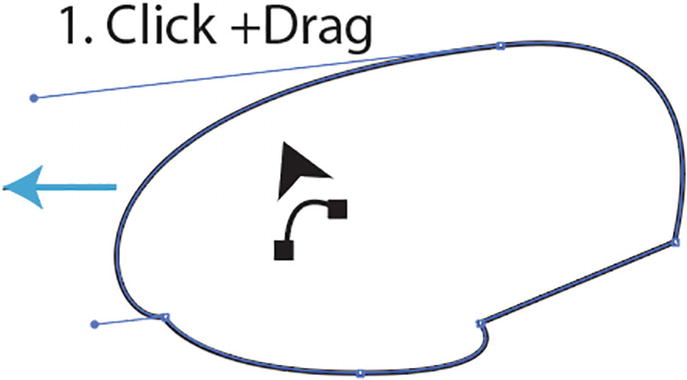
The Curvature tool can be used to create a curved path as you click and drag and observe the rubber-band preview of the path. Refer to Figure 2-31.
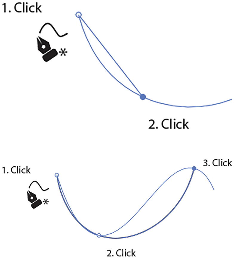
Creating a path with the Curvature tool, and the preview of the path
- 3.
You can close the path when you click on the original point. Refer to Figure 2-32.
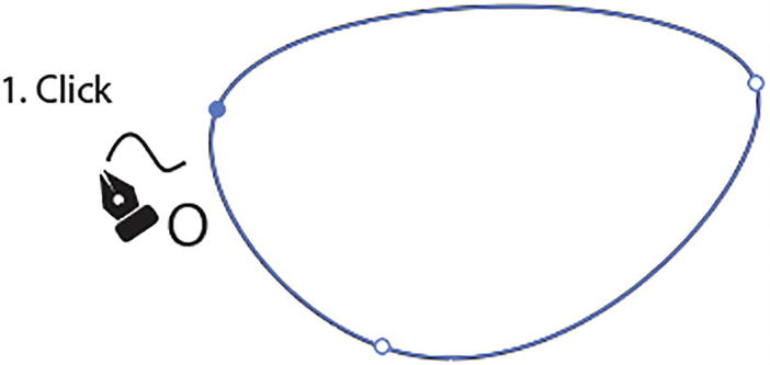
Closing the path with the Curvature tool
- 4.
Once the path is closed, you can select points on the path if you need to move them to scale the path.
- 5.
You can also add points to the selected path by clicking on a part of the path. Refer to Figure 2-33.
Adding points to the path with the Curvature tool
- 6.
As with the Pen tool, you can hold down the Ctrl/CMD key to release on the next click on the artboard and keep the path open.
- 7.
You can also use the Shift key while clicking to keep the anchor points level.
- 8.
Hold down the Alt/Option key or double-click as you click to create a straight part of the path. Refer to Figure 2-34.
Creating straight paths and corner points with the Curvature tool
- 9.
While a point is selected, press the Backspace/Delete key to remove the point but not the path. Refer to Figure 2-35.
Deleting points from the path with the Curvature tool
- 10.
Once that path is complete, Double-click on a point when you want to make it cornered or curved. Refer to Figure 2-36.
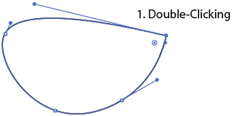
Change the point of a path from corner to smooth and curved by double-clicking with the Curvature tool
Likewise, you can switch to the Pen tool at any time to complete or edit the path. You can refer to my file curve_practice_diagram.ai.
Swapping Fill and Stroke Colors with the Pen Tool
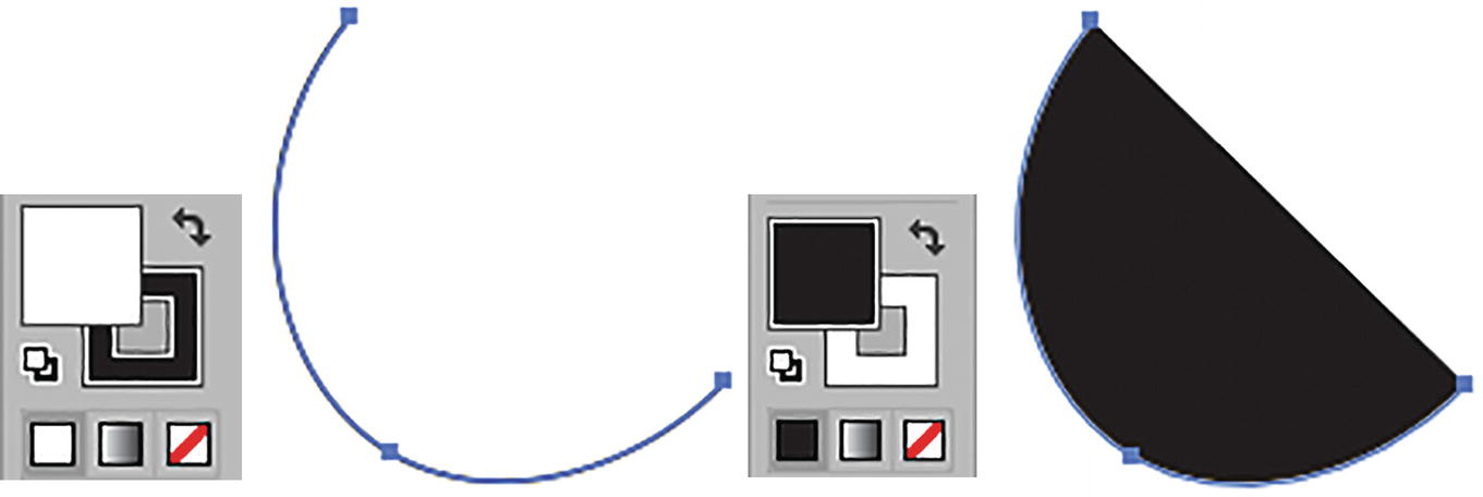
Swapping the fill and stroke for an open path using the Toolbars panel while the path is selected
While drawing, you can switch or swap the stroke and fill colors by pressing Shift + X.
Creating a template layer to trace over for practice
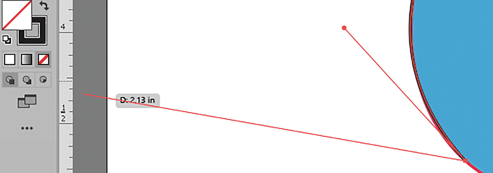
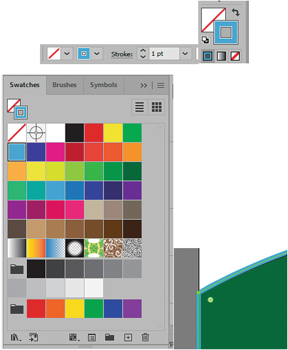
Setting the fill to none while using the Pen tool for tracing
While using the Pen tool you can easily click on the Toolbars panel and switch the fill to none. Do so by clicking on the square with the red slash through it while the fill is in front of the stroke. Refer to Figure 2-39.
This will make it easier to trace over the template or underlying graphic.
Besides having a path with no fill, you can also eliminate the stroke while tracing over another path by setting the color to none as well, though doing so makes it difficult to locate the path afterward. Paths with no fill or stroke are used for the purpose of text on a path, clipping masks, or envelope meshes to partly cover a path or a shape. We will see examples of these kinds of hidden paths in Chapters 9 and 10.
If you are interested in reviewing some of the other ways that I trace over images for the start of logo creation, check out the books mentioned in the Introduction.
Selection, Direct Selection, and Group Selection Tools
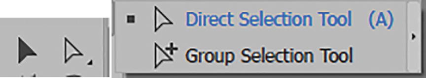
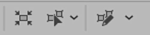
Toolbars panel: Selection tool, Direct Selection tool, and Group Selection tool
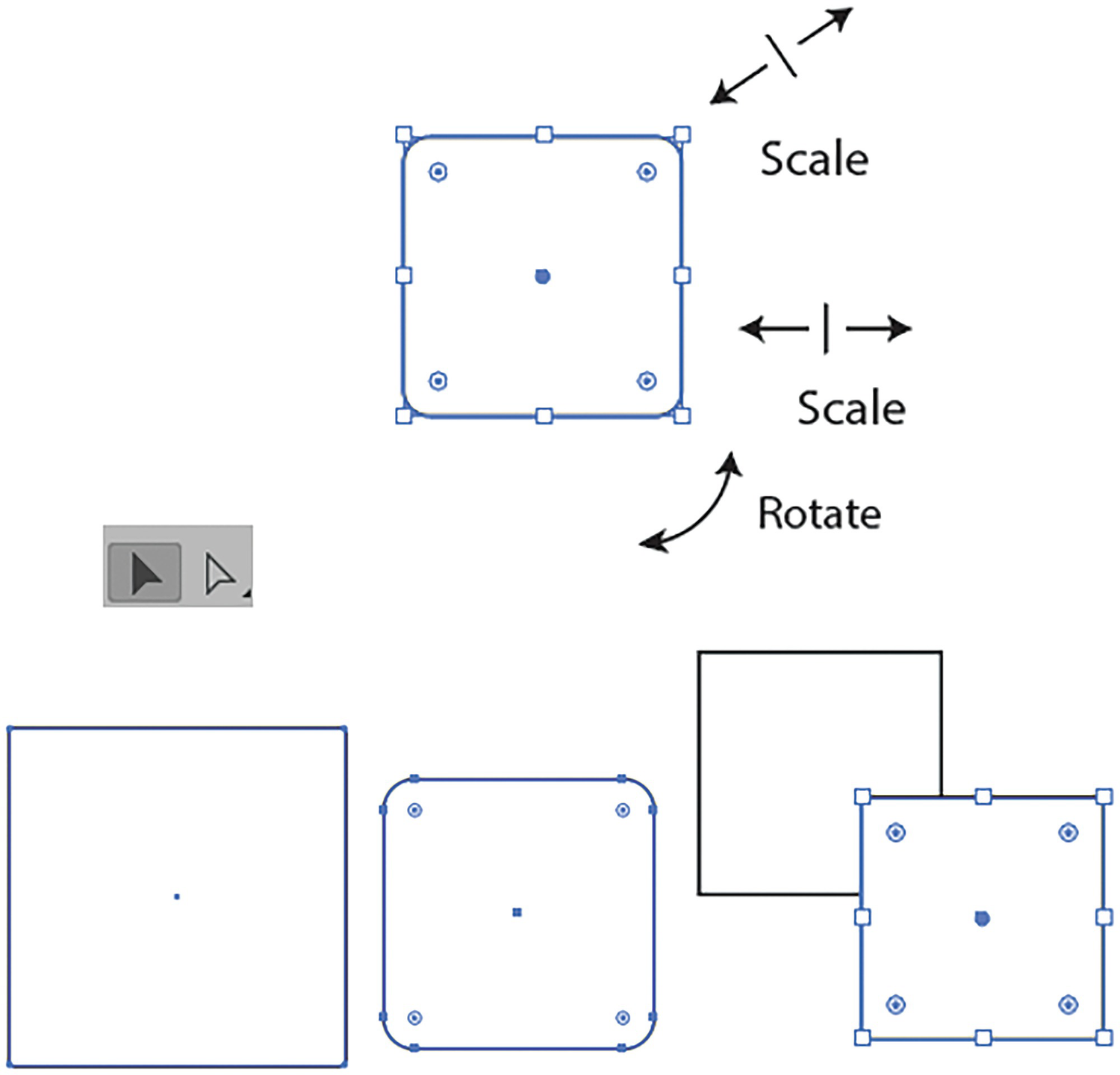
Selection Tool (V)
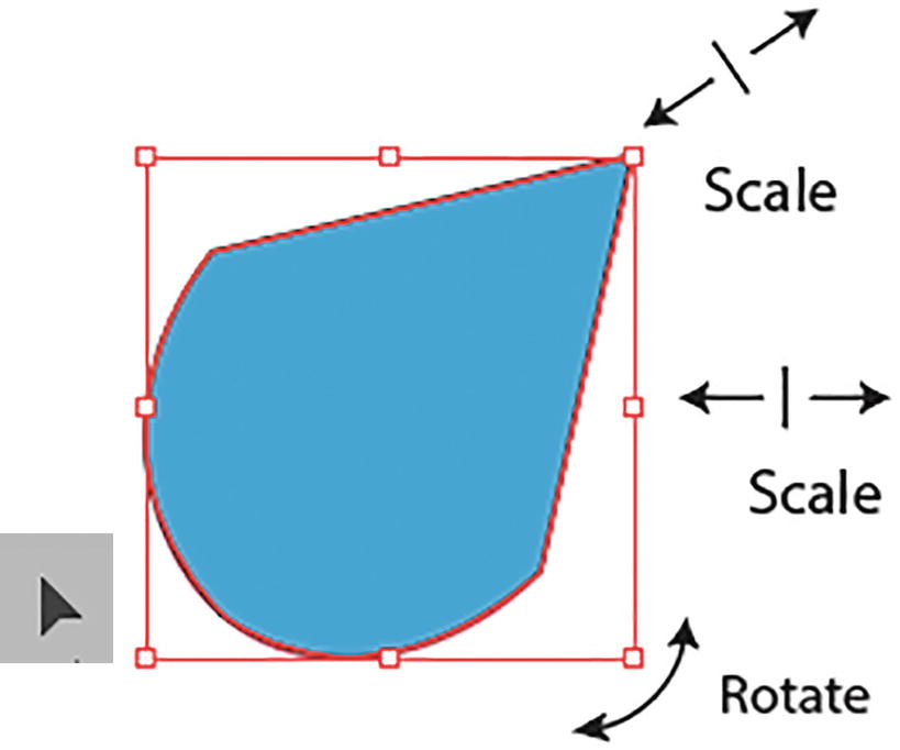
Use the Selection tool to move, scale, and rotate a path
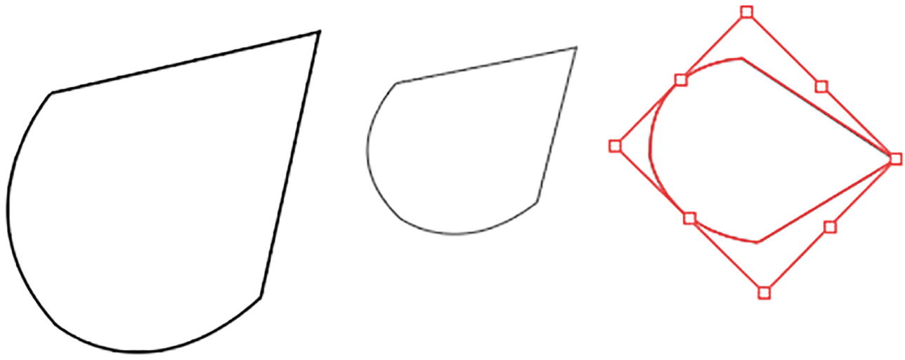
The path is being scaled and then rotated using the bounding box handles
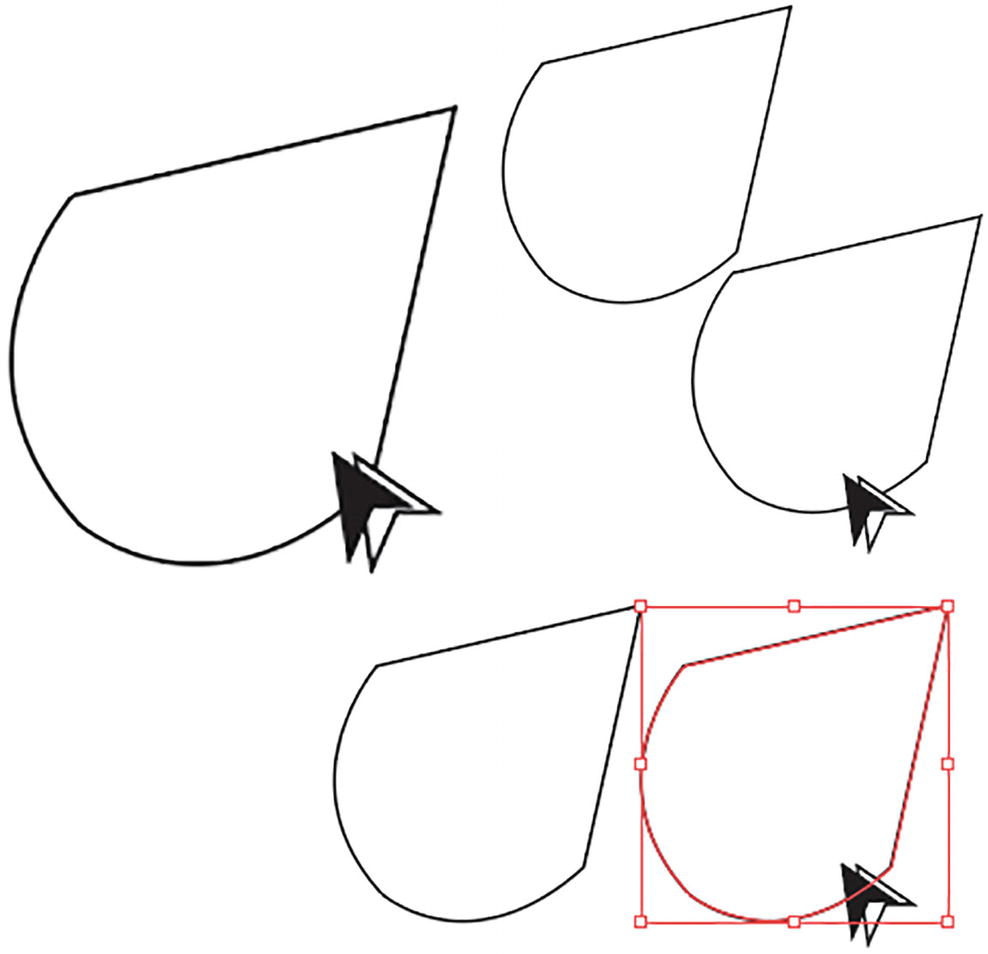
Using the Selection tool, the path is copied when the Alt/Option key is held down while the path is dragged
Or, if you want to delete the selected shape, press the Backspace/Delete key on your keyboard.
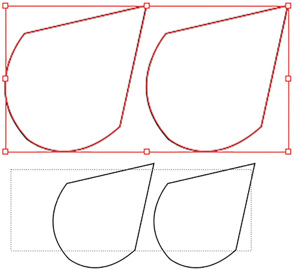
Use the Selection tool to Shift + Click multiple shapes, or drag a marquee around the shapes to select them at the same time
Shift + Click on a selected path to deselect it.
Another way to select is to, with the Selection tool, drag a rectangular marquee around the paths. Refer to Figure 2-44.
You can also use the Select menu to select objects, such as Select ➤ All to select all objects on a layer or Select ➤ Inverse if you want to deselect currently selected items and select those currently deselected. Additional selection options from the Select menu include All, All on Active Artboard, Deselect, and Reselect. Refer to Figure 2-45.
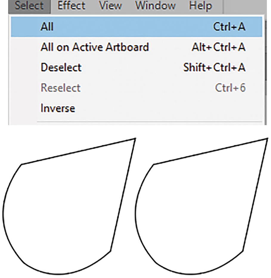
Use the Select menu to select or deselect multiple shapes or objects
To deselect all paths, click off the Artboard, or go to Select ➤ Deselect.
While the path is selected you can use the Control panel or Properties panel to adjust the various object settings.
Control Panel Options for Paths

Use the Control panel to adjust options on the path
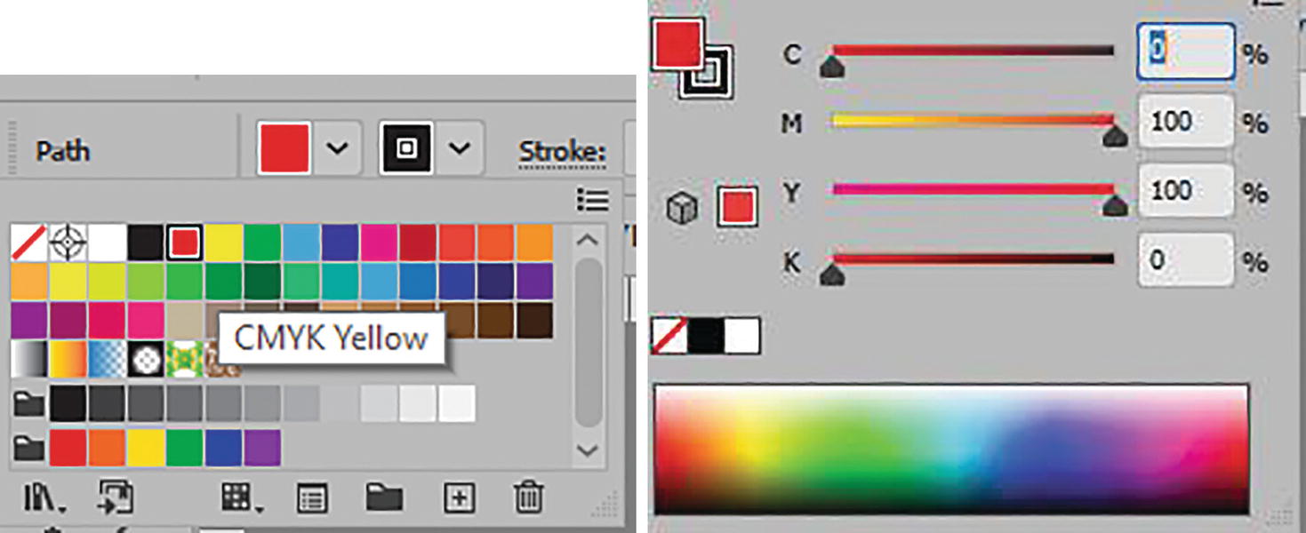
Control panel path options for fill color
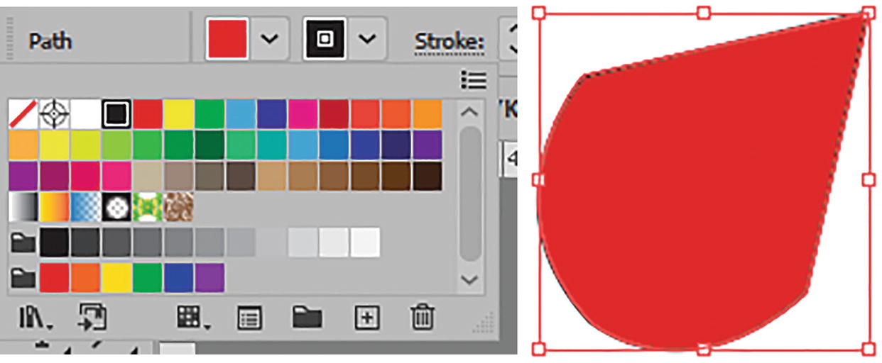
Control panel path options for setting stroke color while path is selected
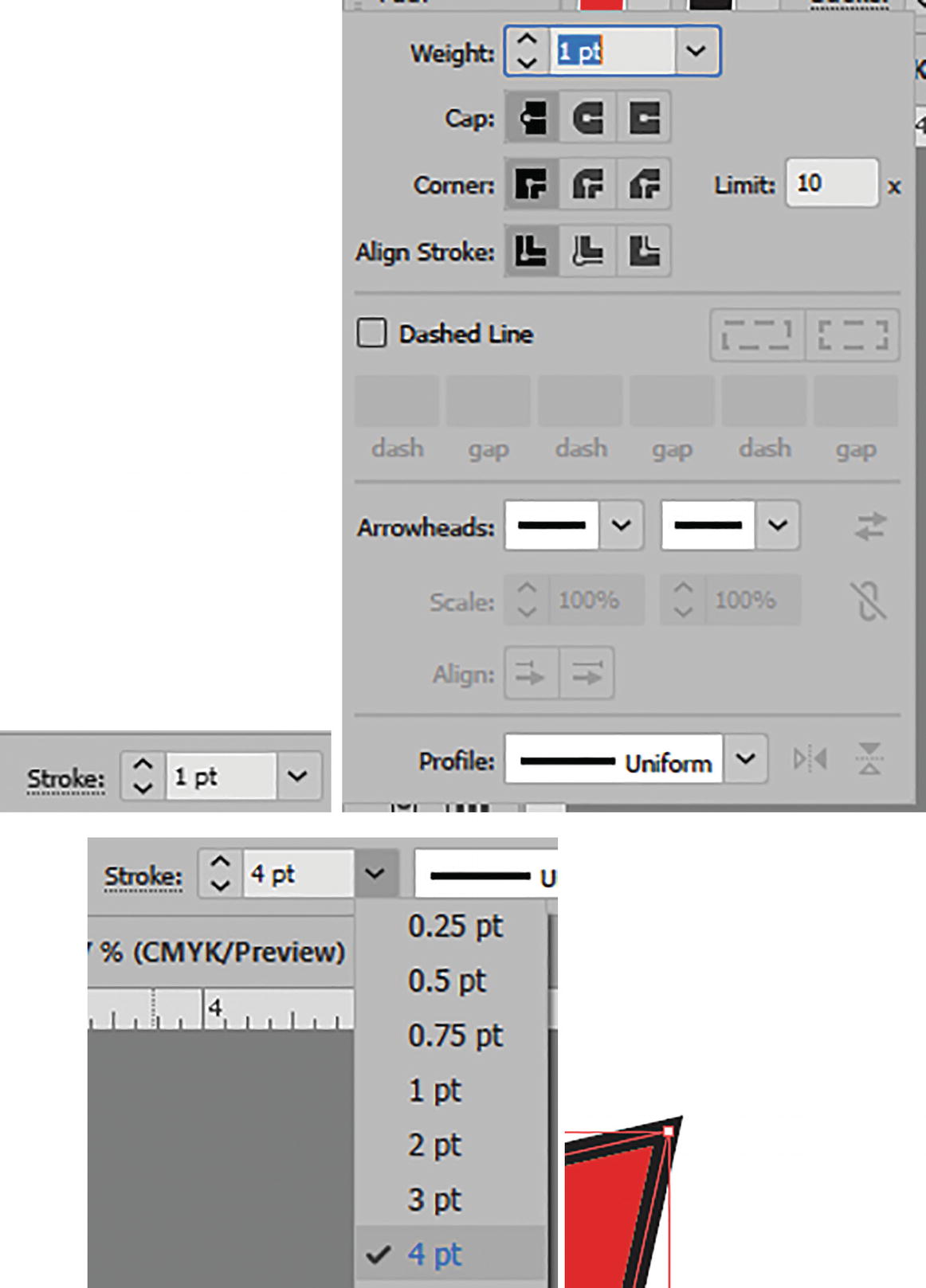
Control panel path options for setting Stroke and Stroke Weight for a selected path
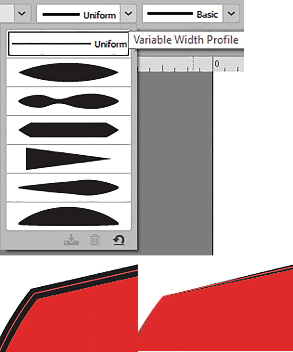
Control panel path options for setting variable-width profile while path is selected
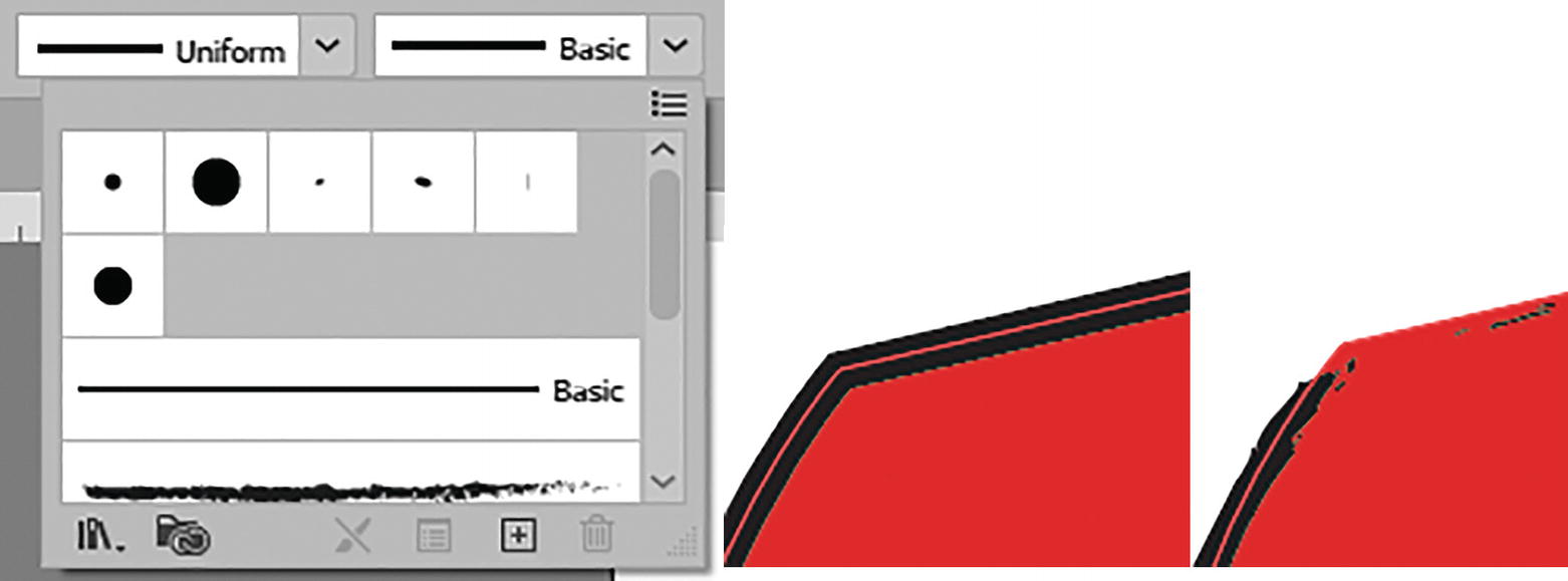
Control panel path options menu for setting brush definition while path is selected
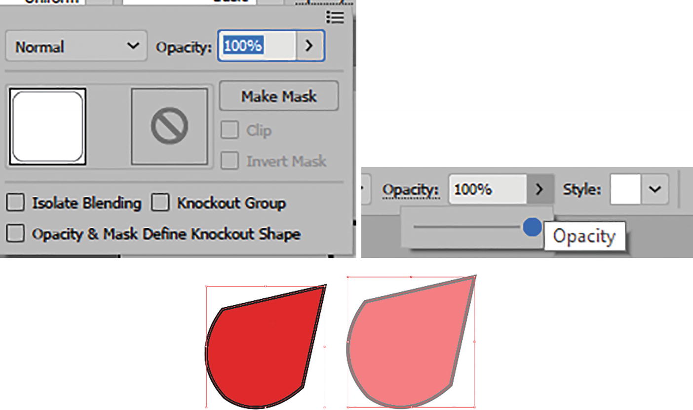
Control panel path options and slider for setting opacity while path is selected
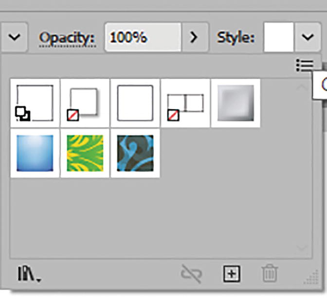
Control panel path options for setting a graphic style while path is selected; currently no graphic style is chosen
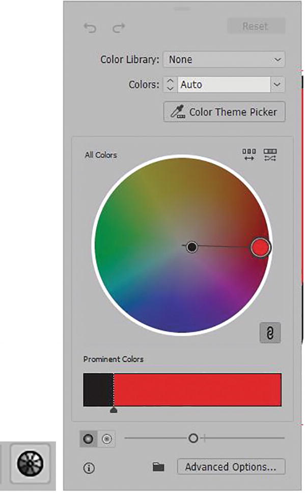
Control panel path options for recoloring artwork while path is selected
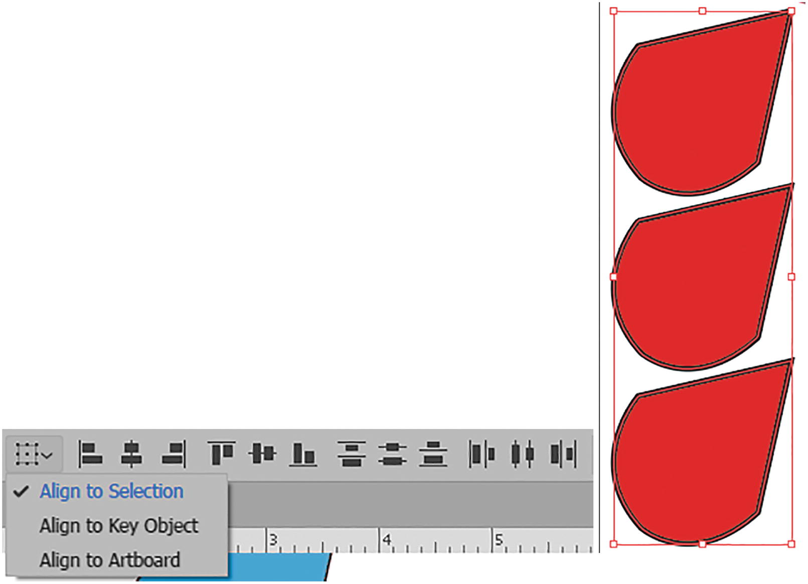
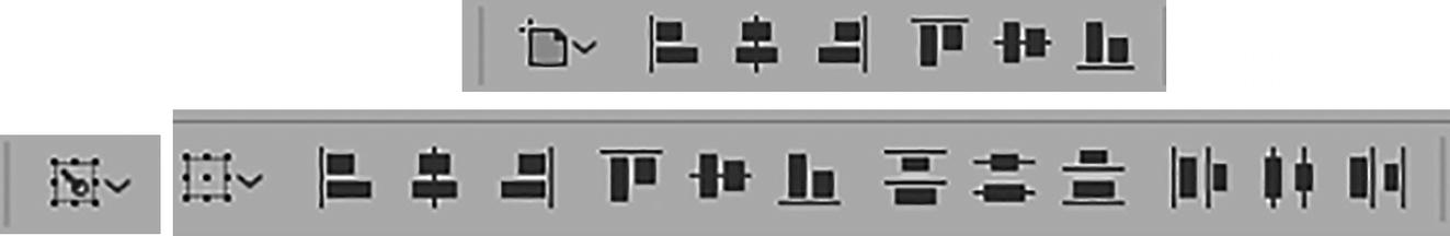
Control panel path options for setting alignment while paths are selected
Align: As in Photoshop with selected layers, when you have two or more paths selected with the Selection tool, you can align them by Selection, Key Object, or Artboard by their Horizontal Align (Left, Center, or Right) and Vertical Align (Top, Center, or Bottom). With three or more, the setting is for Vertical Distribute (Top, Center, Bottom) and Horizontal Distribute (Left, Center, Right). These same settings can also be accessed from the Align panel. I will review the Align panel near the end of this chapter before we look at the project. Refer to Figure 2-55.
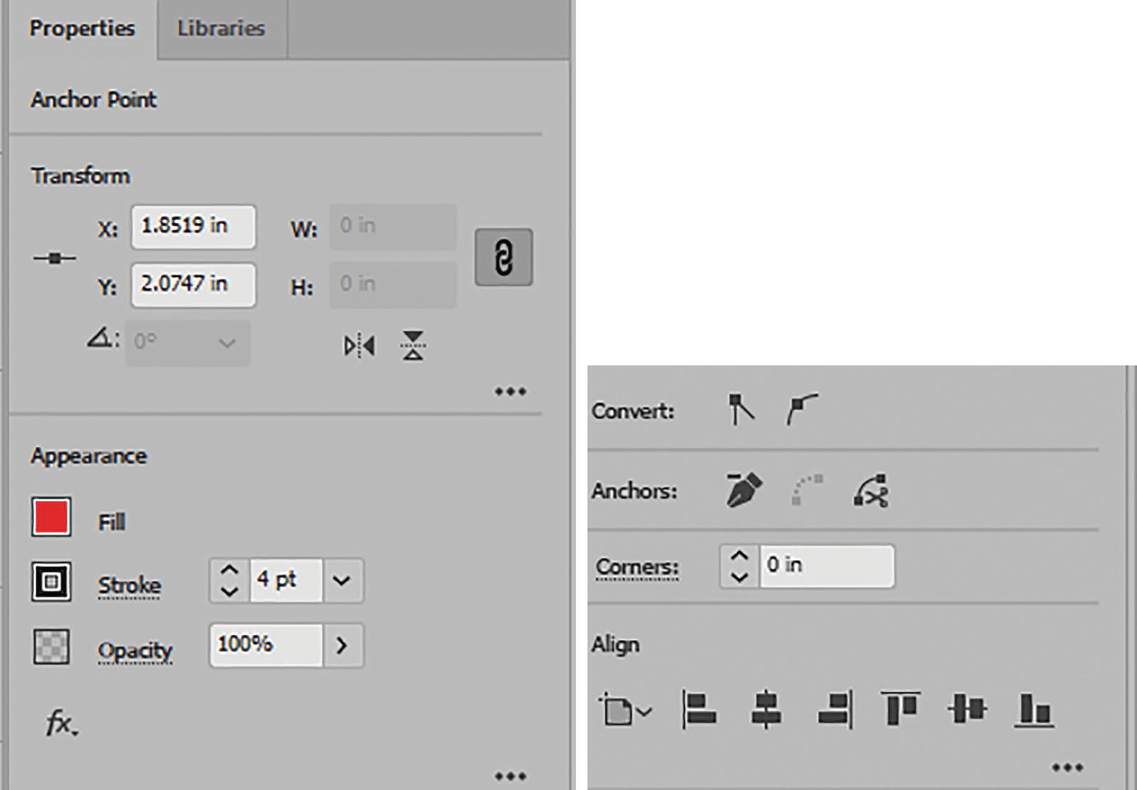
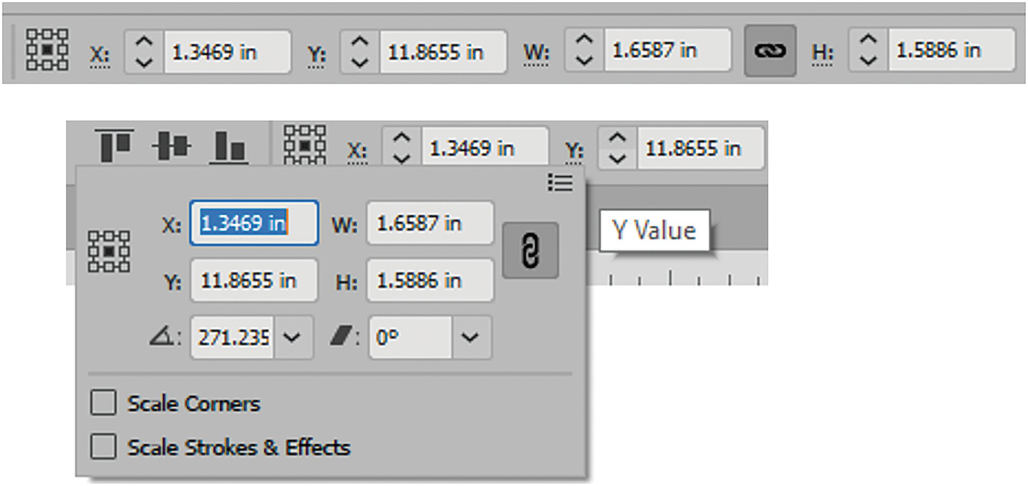
When a selected object (path or shape) is moved or scaled using the Control panel, you can first set the reference point. By default, I leave it as the center mark. You can then type in or use the up and down arrows in the text box to move the shape based on the X and Y coordinates. This is easy to see in inches, as you set this earlier when you created the document.
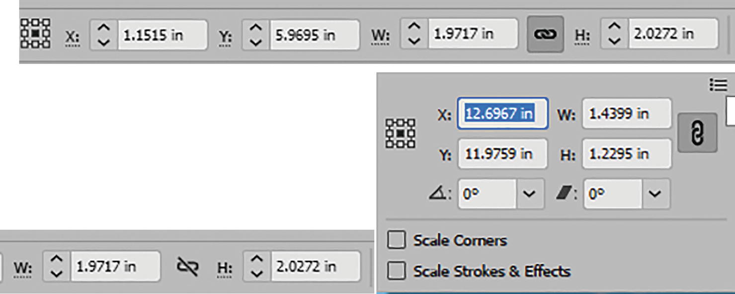
Control panel path options for setting X and Y coordinates and width and height while path is selected
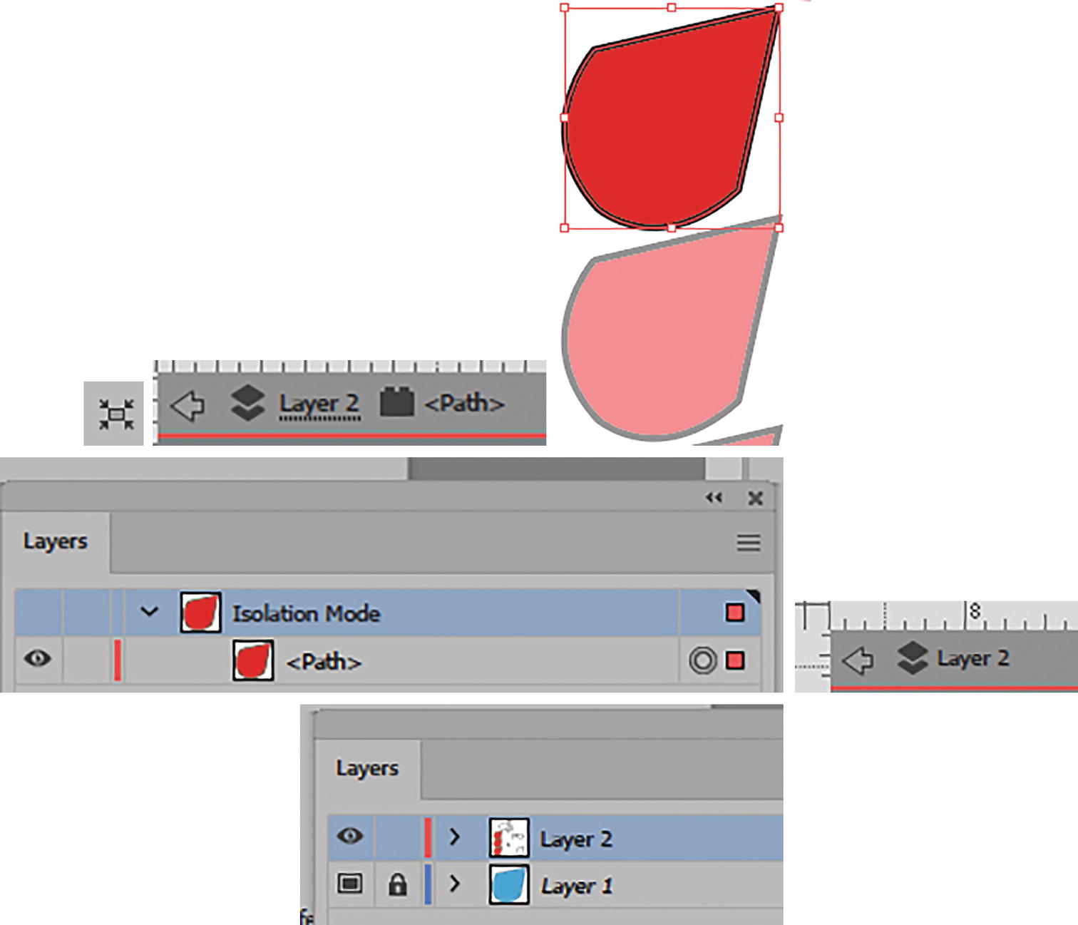
Control panel path options for setting the path into Isolation mode while path is selected
To exit Isolation mode, click on the back arrow twice just below the rulers on the left. This returns you to Normal mode, or in this case Layer 2. The path then becomes deselected. Select the path again with the Selection tool. We will see similar isolation for editing being used in Chapter 7 for patterns and Chapter 6 for symbols. Refer to Figure 2-57.
The last area, while not part of the topic of this chapter, is for the following:
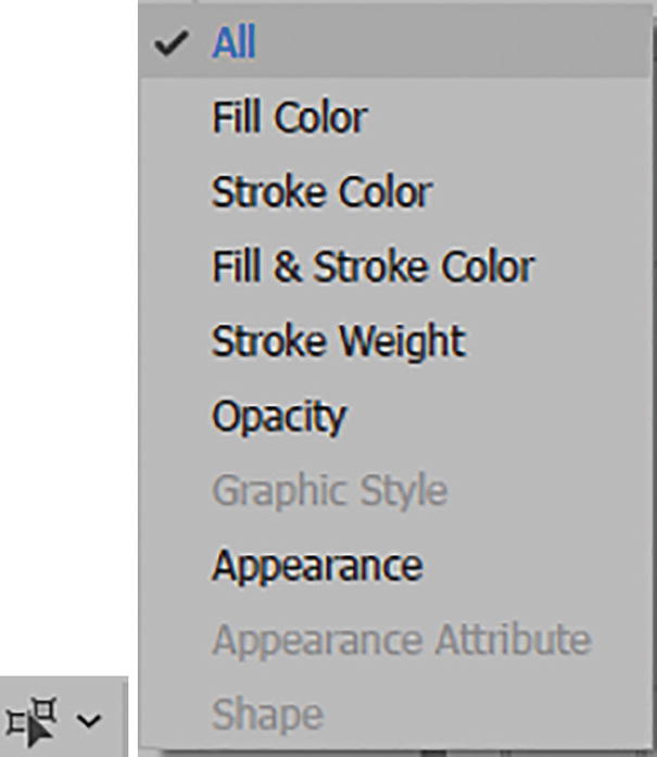
Control panel path options for selecting similar objects while the current path is selected
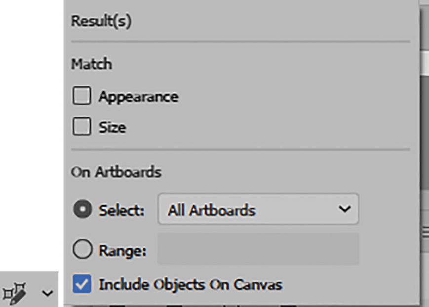
Control panel path options for global edits while a path is selected
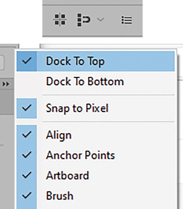
Additional Alignment and Control panel options found in the Control panel menu
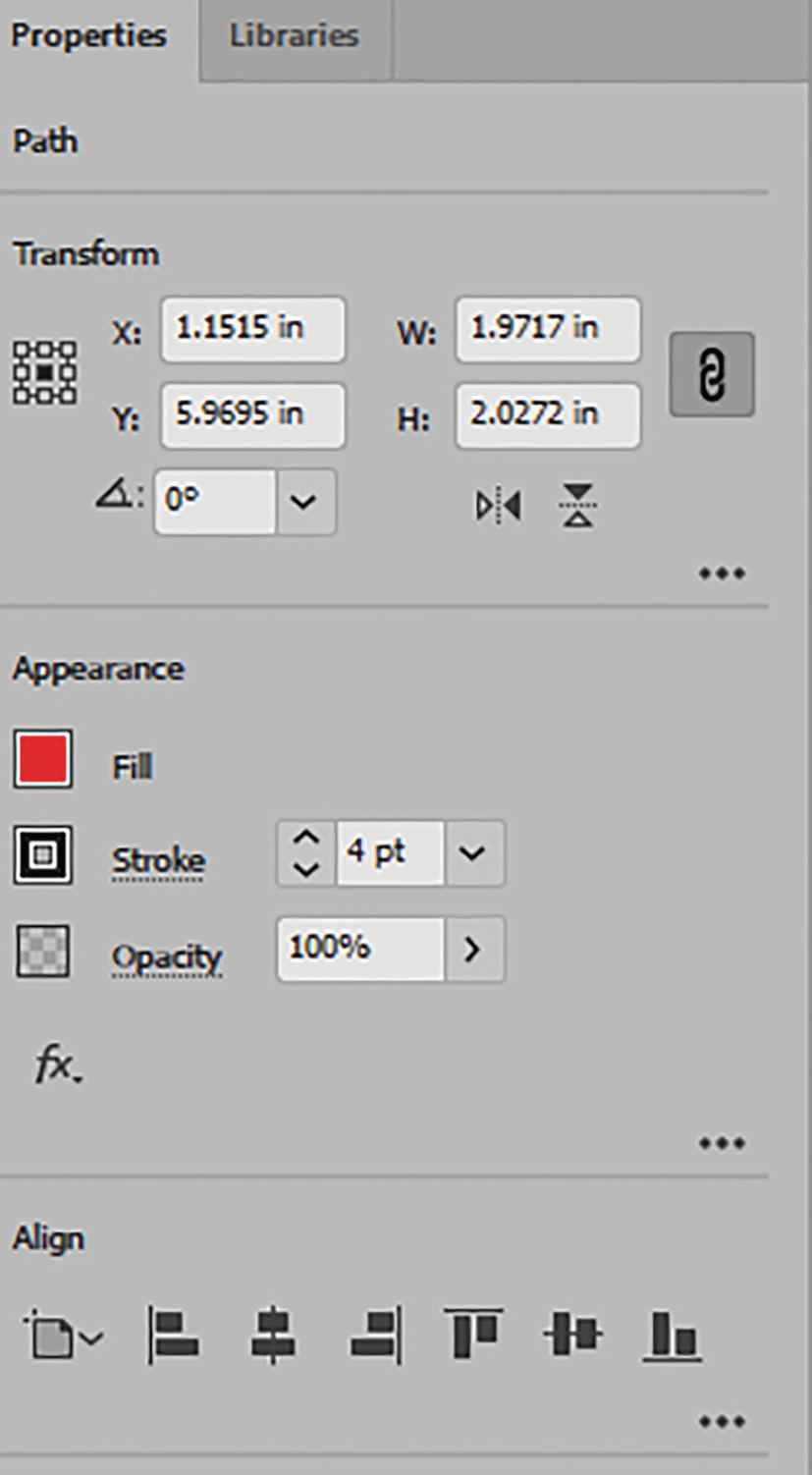
Properties panel with similar settings as the Control panel
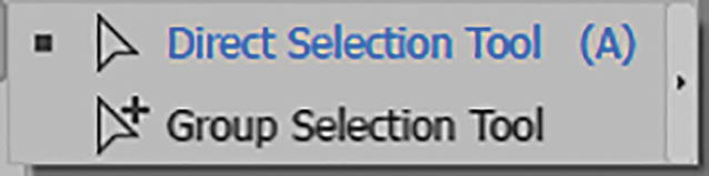
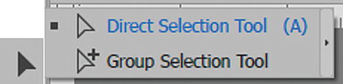
Direct Selection Tool (A)
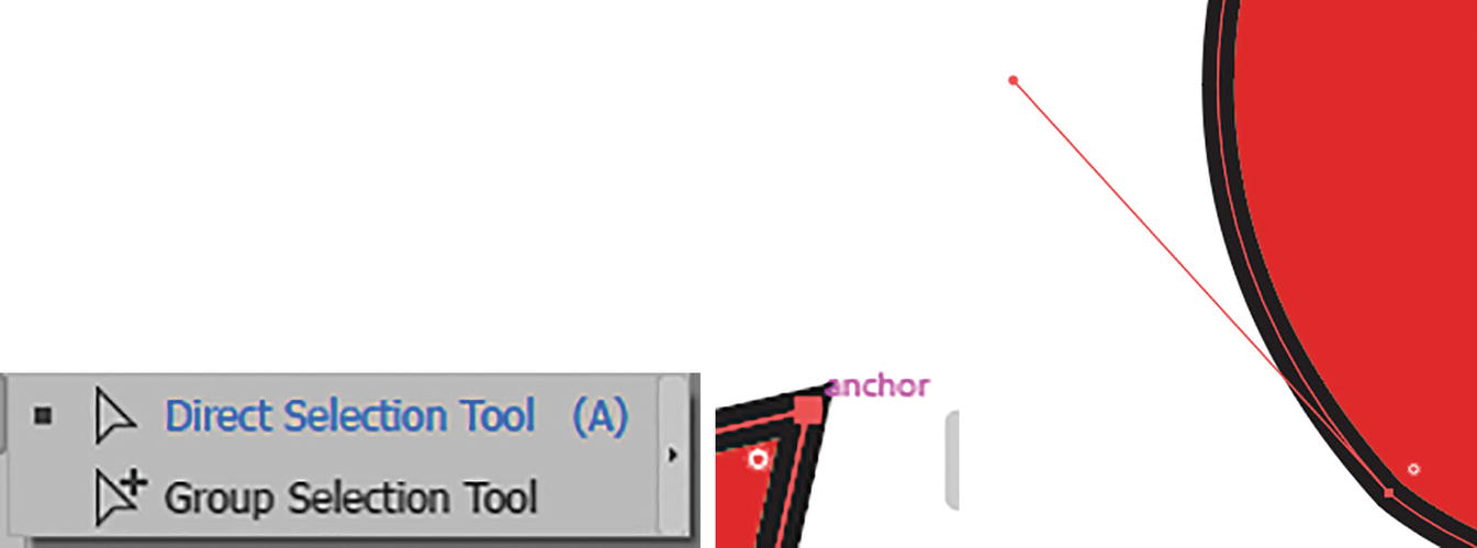
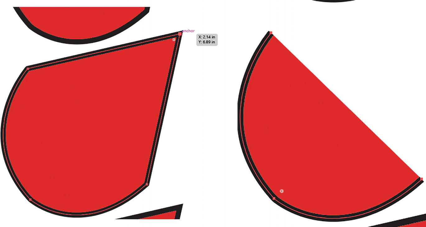
Direct Selection tool selects an anchor point on a path, and you can drag on a point to move it or a handle
You can move the selected anchor point with the tool. You can Shift + Click multiple anchor points to move them in unison, or Shift + Click to deselect certain points.
Deleting a selected point on a path with the Direct Selection tool makes it an open path
Press the Backspace/Delete key again to delete the whole shape. Use Edit ➤ Undo (Ctrl/CMD+Z) a few times, or use the History panel if you need to undo those last steps. Refer to the end of Chapter 1 if you need to review this panel.
Control Panel Options for Anchor Points
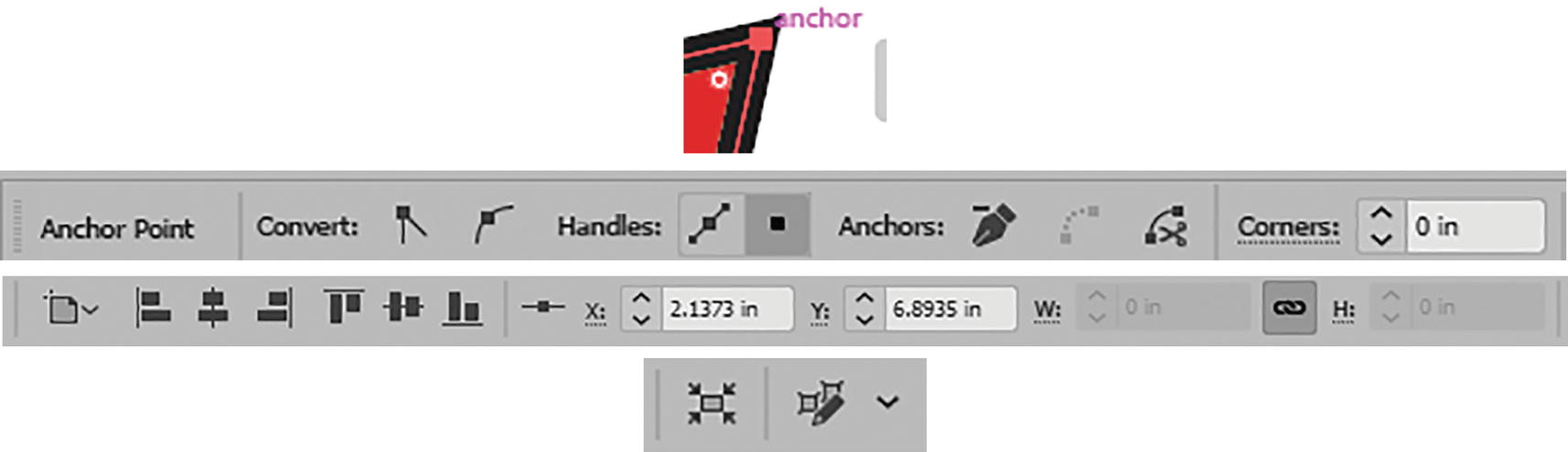
Control panel options for a single selected anchor point
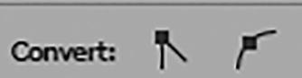
Control panel Convert options
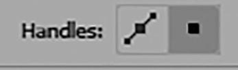
Control panel handles options
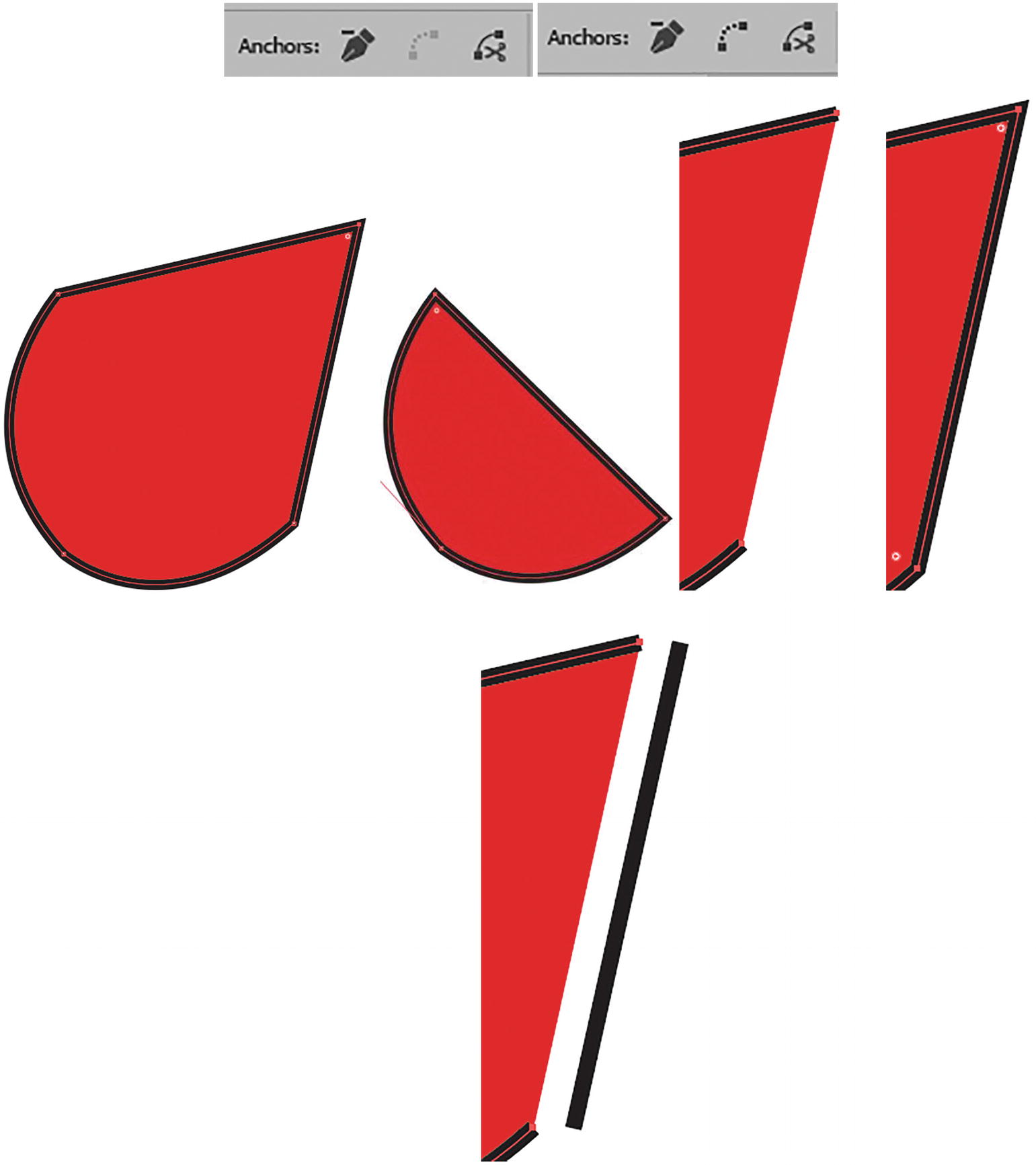
Control panel anchor point options and the effects of the three (remove, connect, and cut) on a path
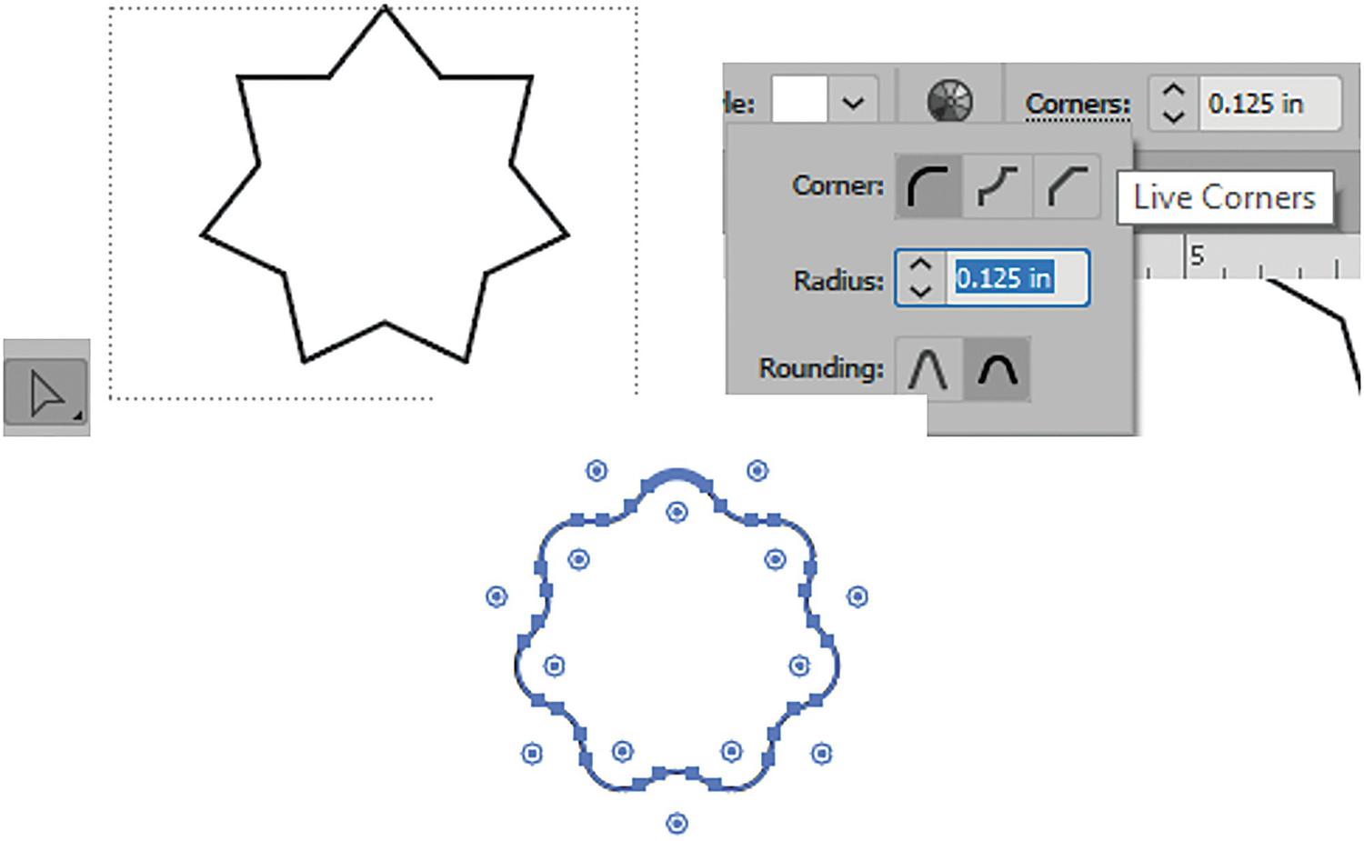
Various corner options, such as Round, Inverted Round, or Chamfer.
Radius: This is the same settings as the text box next to the word “Corners” outside of the dropdown menu.
Rounding: Can be set to Relative or Absolute. You can also adjust the rounding and the radius by dragging on the live corner widgets, as you will see with various shape tools in the next section of this chapter. Refer to Figure 2-68.
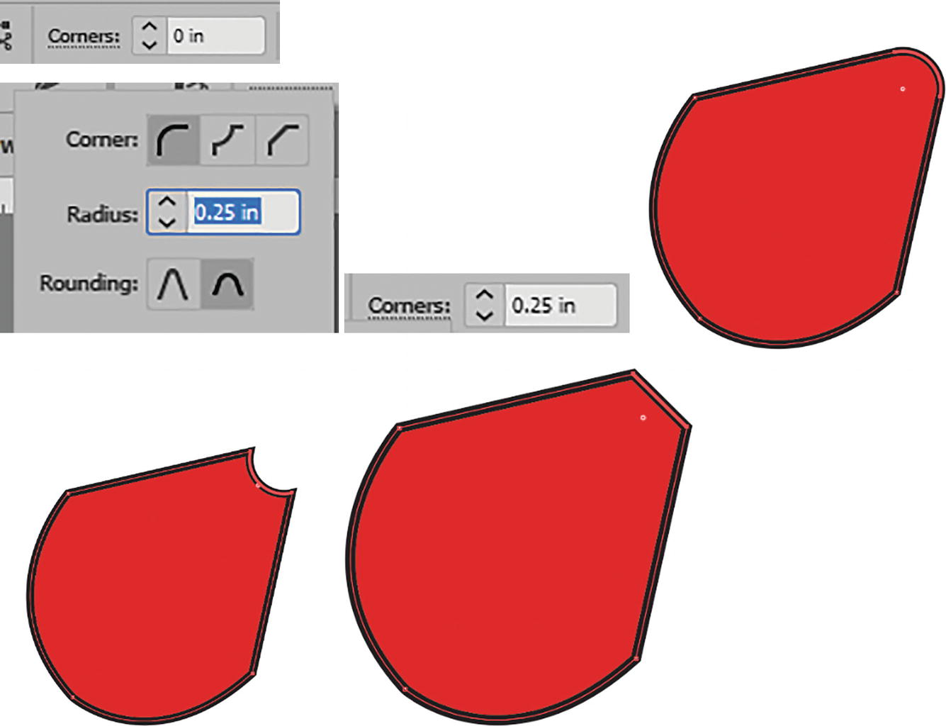
Control panel anchor point options and their effects on a point on the path
Rounding is more apparent when the radius is set higher.
Control panel anchor point options for alignment of selected points on a path

Control panel anchor point options for X and Y coordinates for a single point on a path

Control panel anchor point options for X and Y coordinates and the width and height values (usable when you Shift + Click multiple points on a path with the Direct Selection tool)
Settings for Isolate Selected Object and Start Editing Similar Shapes Together options are the same as with the Selection tool. Refer to Figure 2-71.
Properties panel for a single anchor point selected with the Direct Selection tool
To deselect a point and the whole object, click outside the Artboard or off the object.
Group Selection Tool
Toolbars panel Group Selection tool
Select two paths with the Selection tool and use the Object menu to turn it into a group
To ungroup paths, while they are selected, choose Object ➤ Ungroup (Shift+Ctrl/CMD+G).

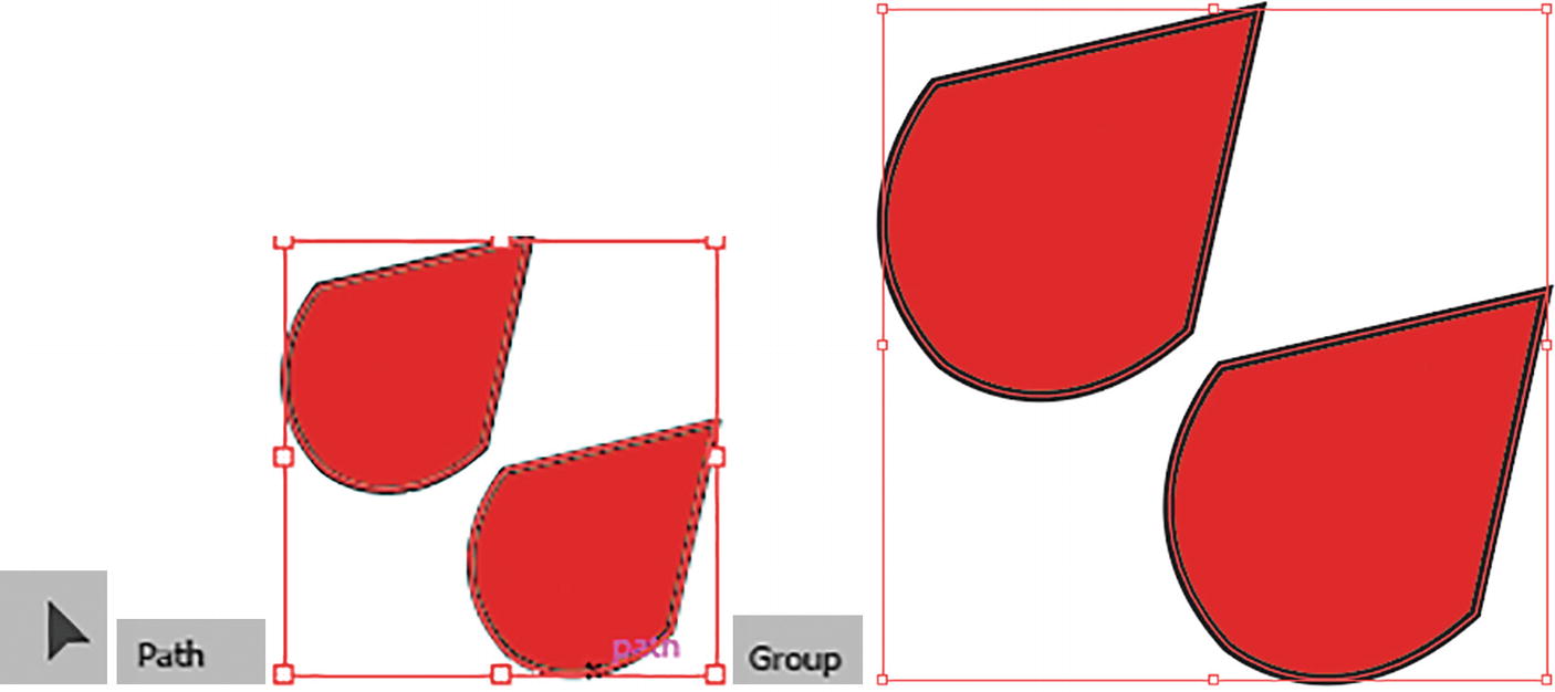
Use the Group Selection tool to select a single path within a group and drag to move
With one path selected with the Group Selection tool, you could return to the Selection tool and edit only that path using the Control panel. Refer to Figure 2-76.
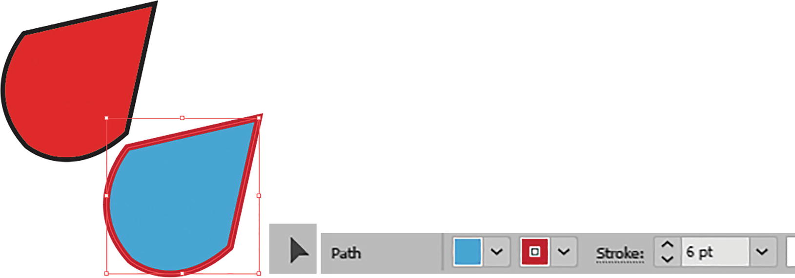
Once a path is selected with the Group Selection tool, you can switch to the Selection tool and use the Control panel to modify the path’s fill, stroke, and stroke weight

The Properties panel will have the caption of group while the group is selected
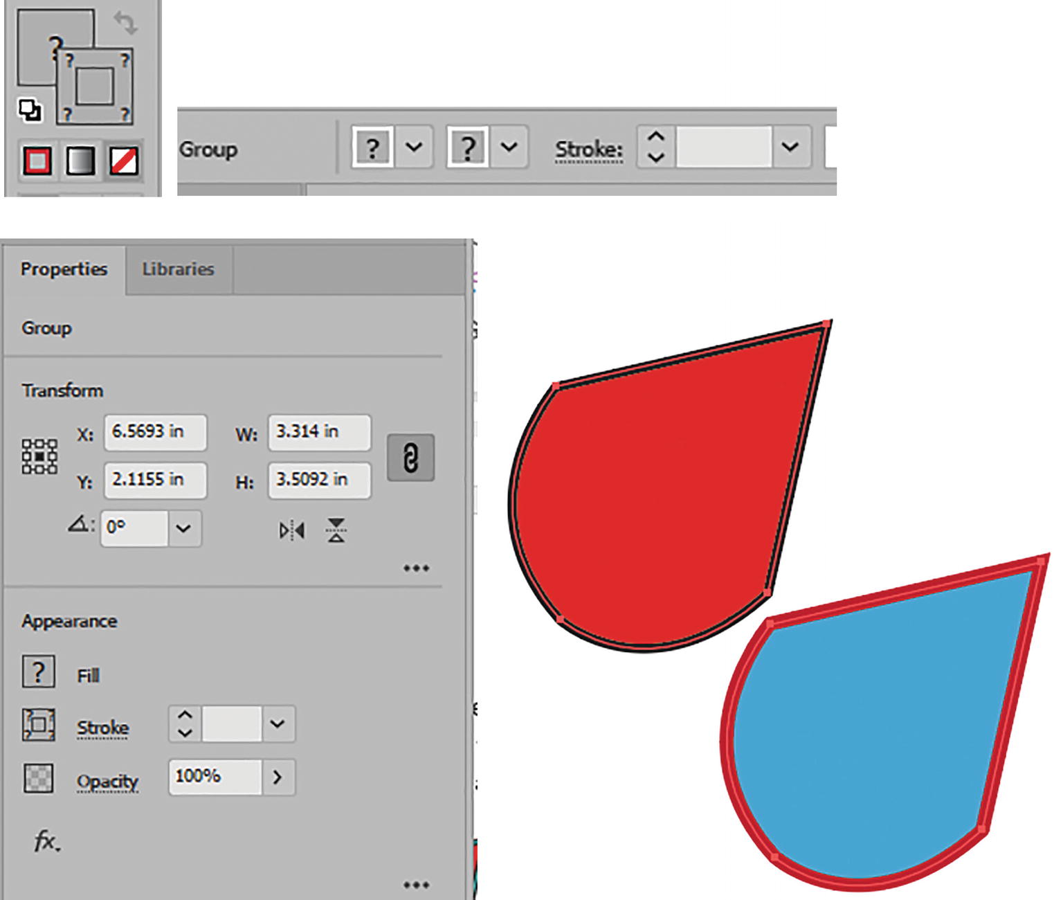
When paths are different within a group, in the Toolbars, Control, and Properties panels certain boxes may appear with a [?] or appear blank
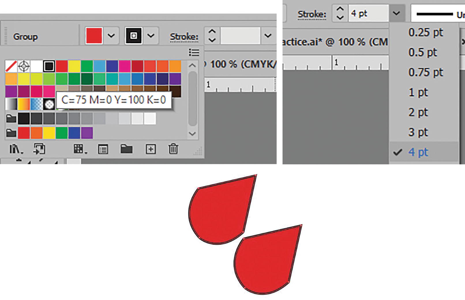
Use the Control panel to reset both paths to a common fill color, stroke color, and stroke weight
You can also use the Group Selection tool to move a path without the bounding box handles. Shift + Click each path when you want to select certain paths. Click outside the Artboard or off the object to deselect.
Adjusting Scale of Paths
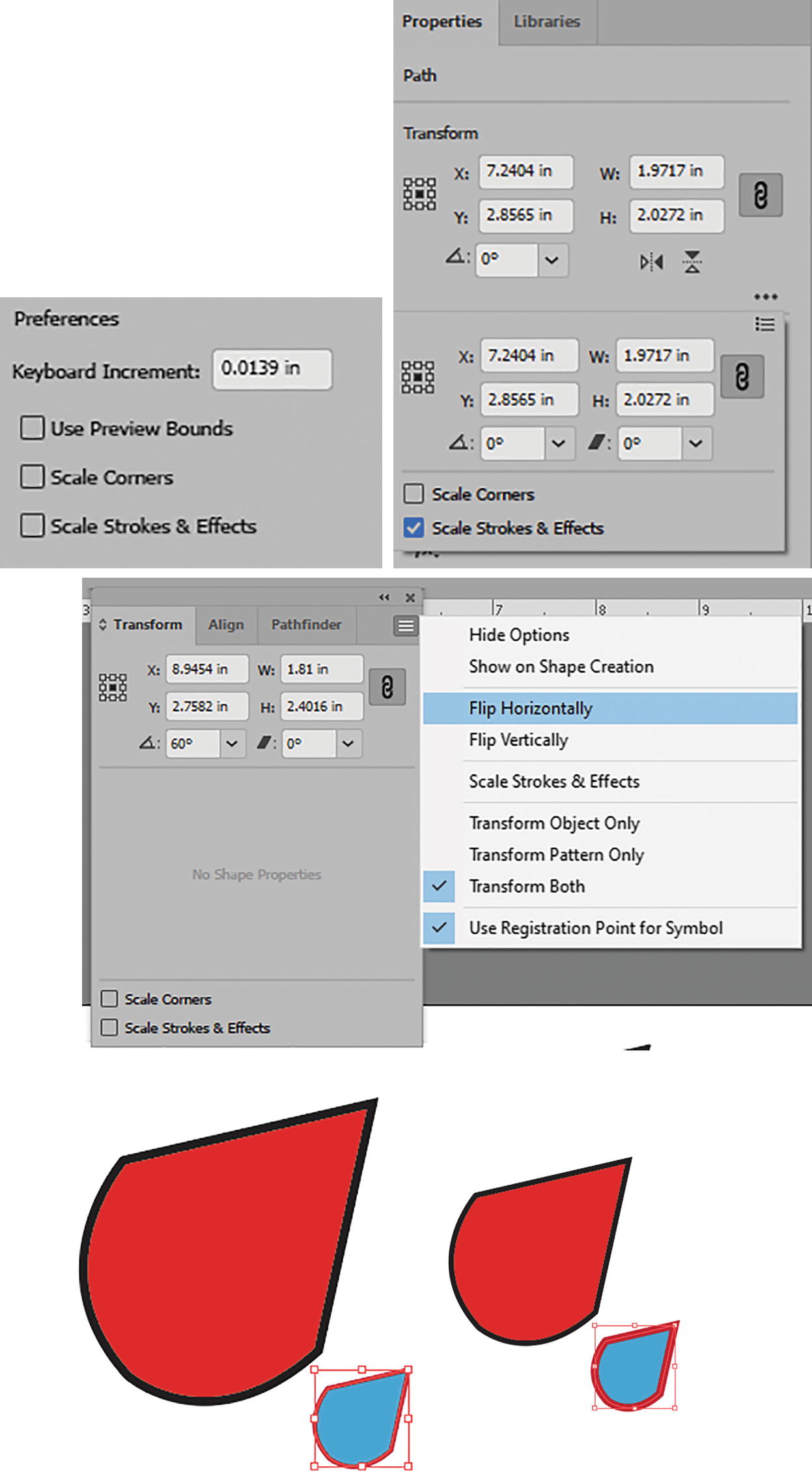
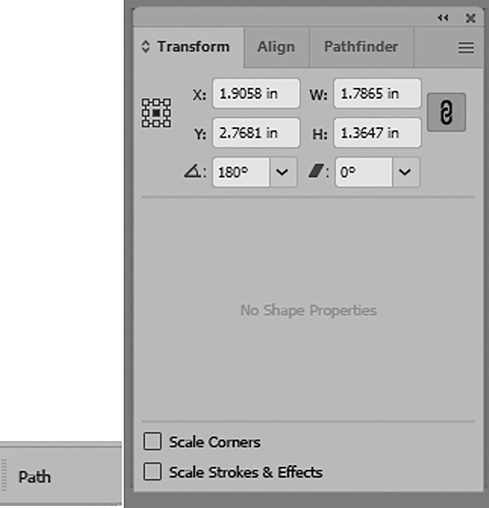
Use the Properties panel to remove the Scale Strokes and Effects settings so that your stroke does not become too small when the path is scaled down. Similar settings are found in the Transform panel
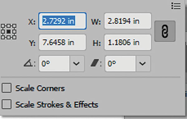
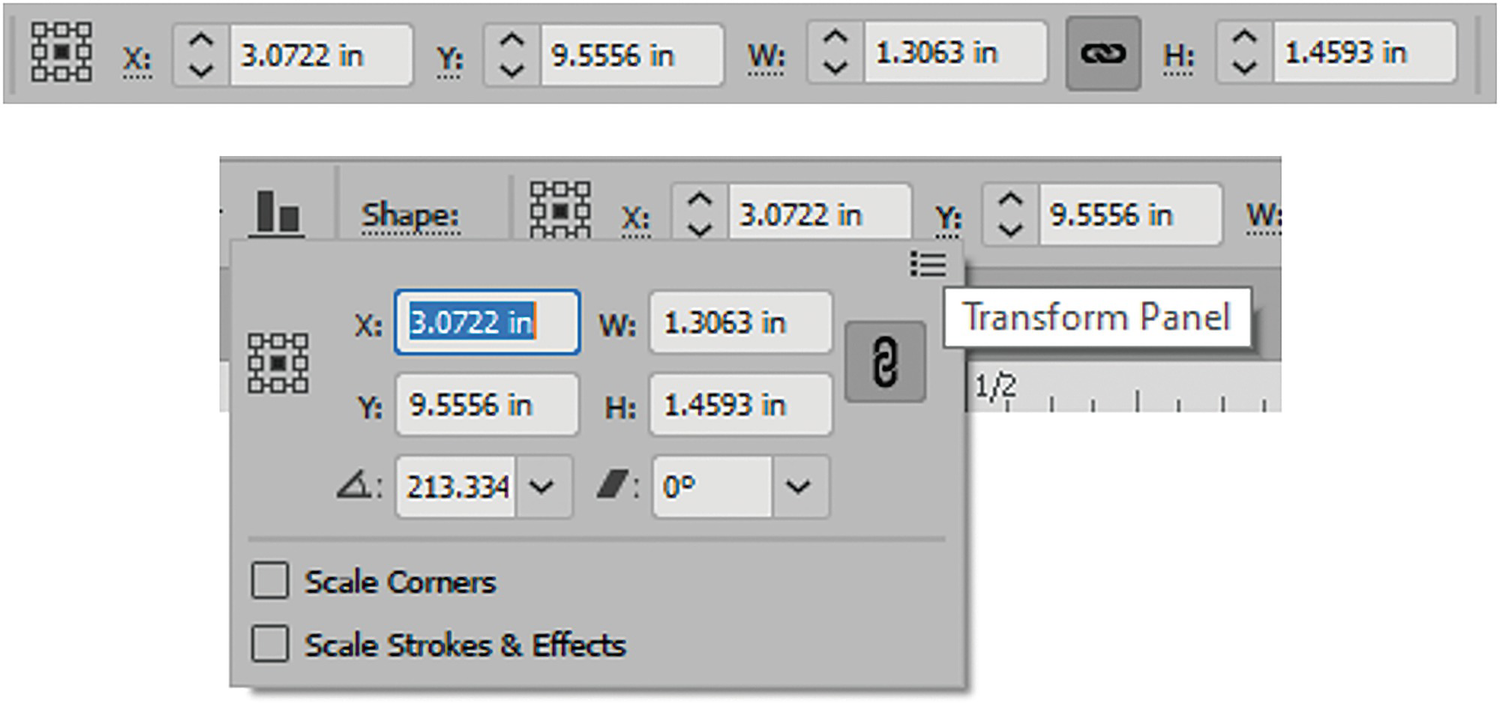
Additional Properties Panel and Transform Panel Options
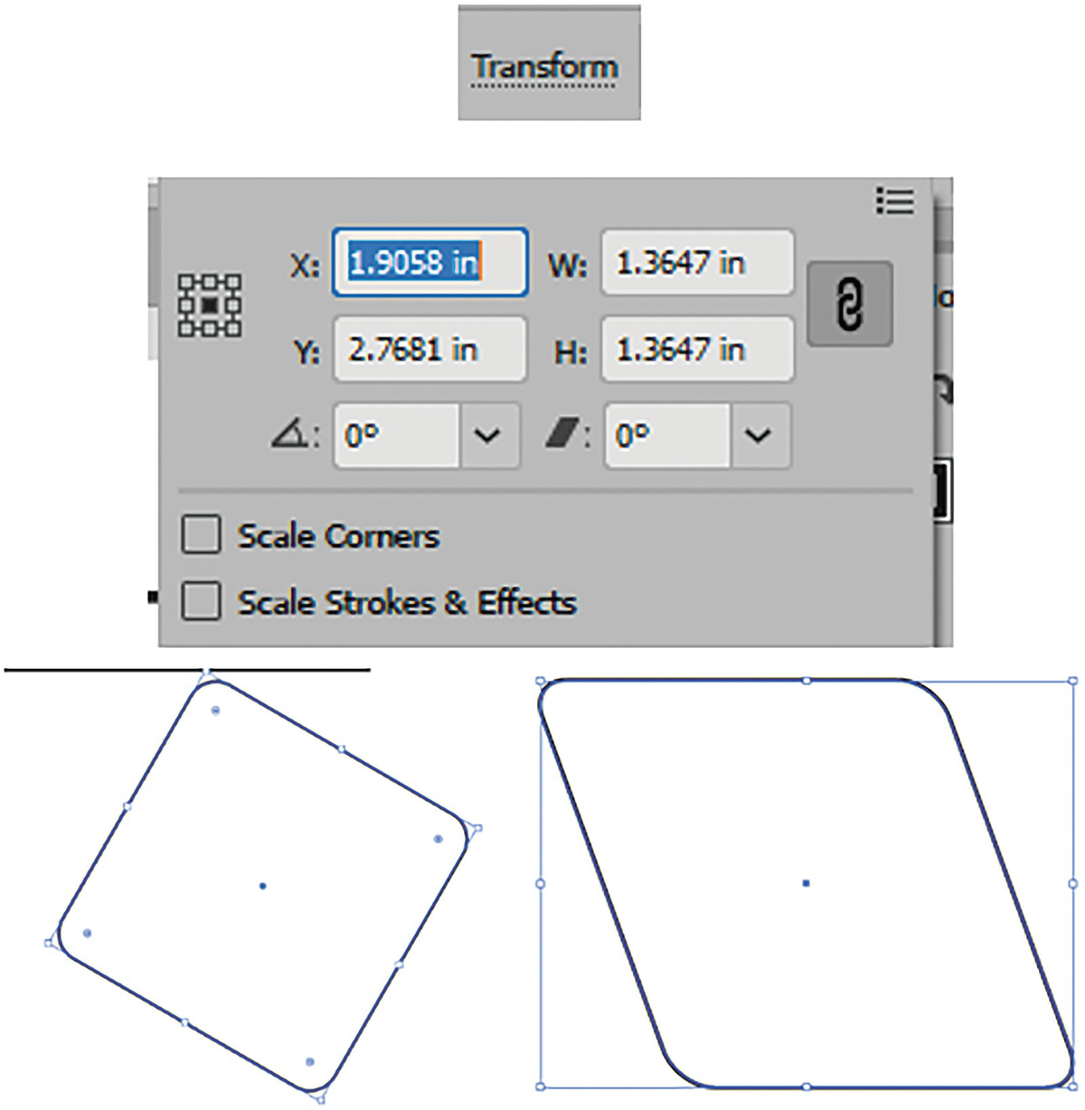
Using either the Properties panel or the Transform panel will reveal additional options. In addition to being able to set the X and Y coordinates of a shape, along with its width (W) and height (H), for which you can link or unlink constrain width and height proportions, there are additional features. Refer to Figure 2-80.
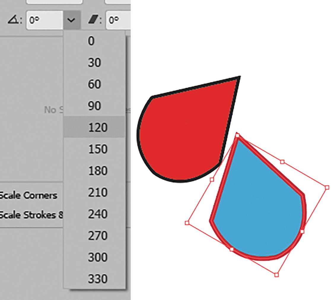
Transform panel Rotate Path menu options
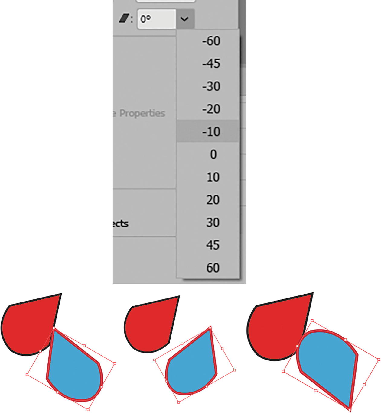
Transform panel Shear Path menu options

Properties panel options for flipping a path horizontally or vertically
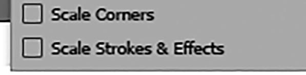
Transform and Properties panels options for Scale Corners and Scale Strokes & Effects
In Chapter 3, we’ll compare the Transform panel to some actual tools for rotation, scaling, shearing, and free transforming.
Currently, in the menu, the transform is set to Transform Both for object (path) and pattern. However, in Chapter 7 we’ll look at that option again. Refer to Figure 2-85.
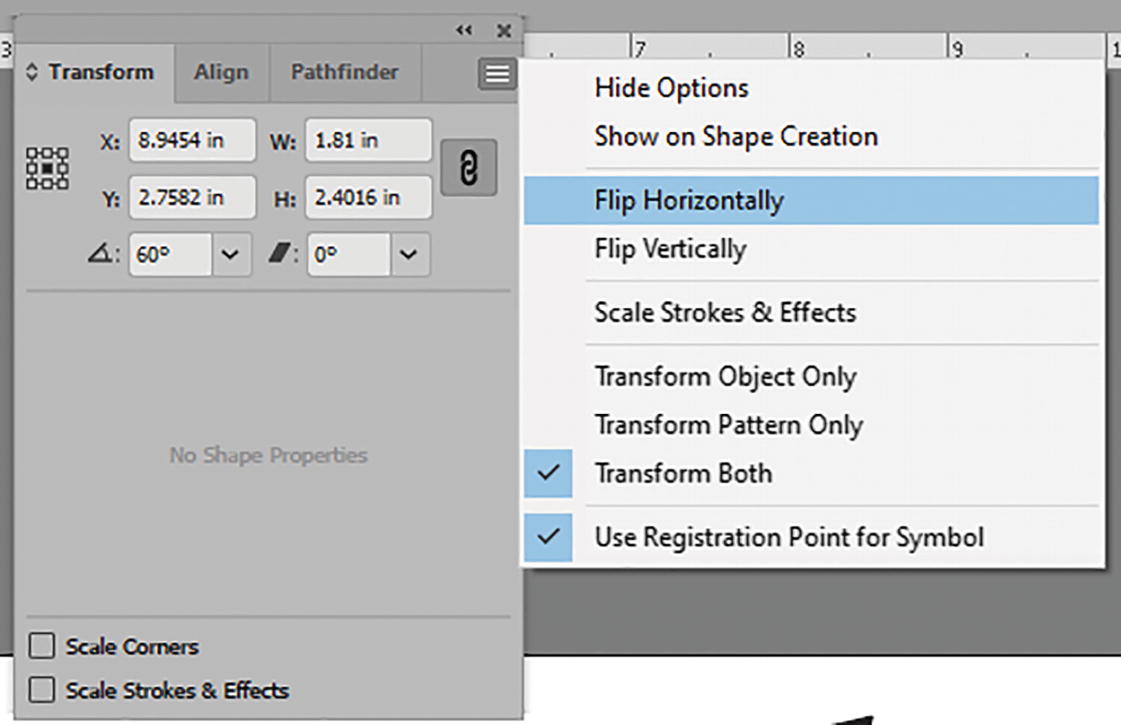
Transform panel and its menu with additional transform options
You can use my file, path_control_practice.ai, if you need some paths to experiment with.
Shape Tools (Rectangle, Rounded Rectangle, Ellipse, etc.)
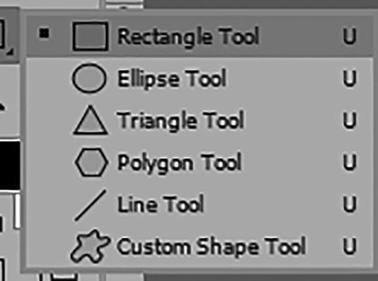
Photoshop Shape tools in its Tools panel
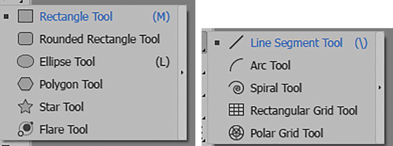
Figure 2-87. Illustrator Shape tools in the Toolbars panel
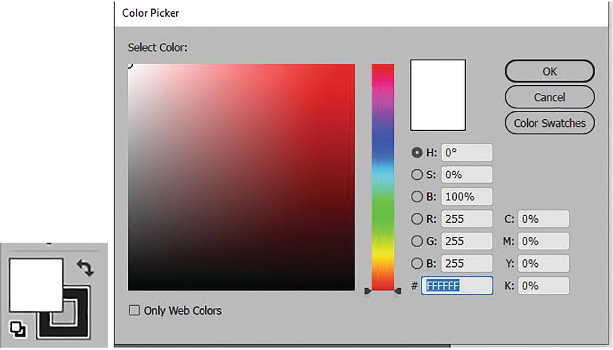
Use the Toolbars panel Color Picker dialog box to set fill and stroke colors
Select a color and click OK to exit.
The settings I am using in the following Shape dialog boxes are in inches because I set my rulers (right-click) to this unit after I chose View ➤ Rulers ➤ Show Rulers. Refer to Figure 2-89.
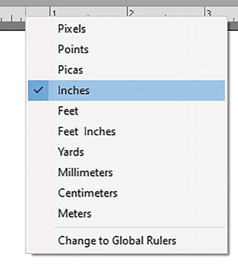
Right-click on one of your rulers so that you can set the increments to inches, if it is not already set
Rectangle Tool (M)
drag out a shape on the Artboard;
hold down the Shift key as you drag if you want to create a square;
press Alt/Option + Shift to drag the rectangle or in this case square from its center point; or
click somewhere on the Artboard with the tool to enter the rectangle dialog box for the width and height. Then, choose with the link whether or not to constrain the width and height proportions. Click OK to commit. Refer to Figure 2-90.
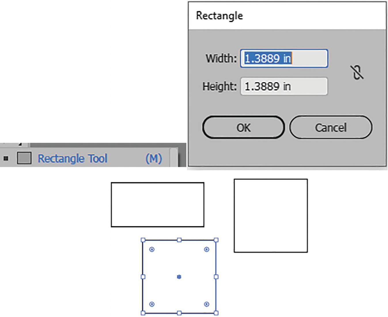
Rectangle tool, dialog box with settings, and various created rectangles
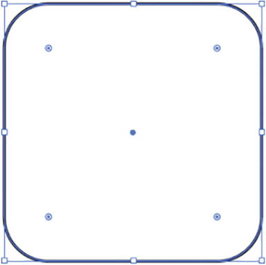
Rounded rectangle created by dragging on corner widgets
Control Panel Options

Control panel settings for Rectangle tool and most Shape tools
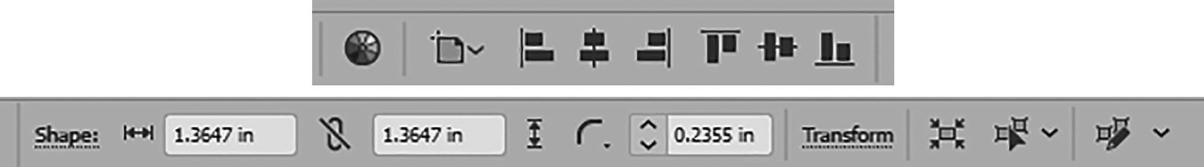
Control panel settings for Rectangle tool and most Shape tools and then specific Shape Properties options for rectangles
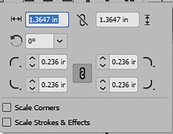
Additional shape properties options for rectangles
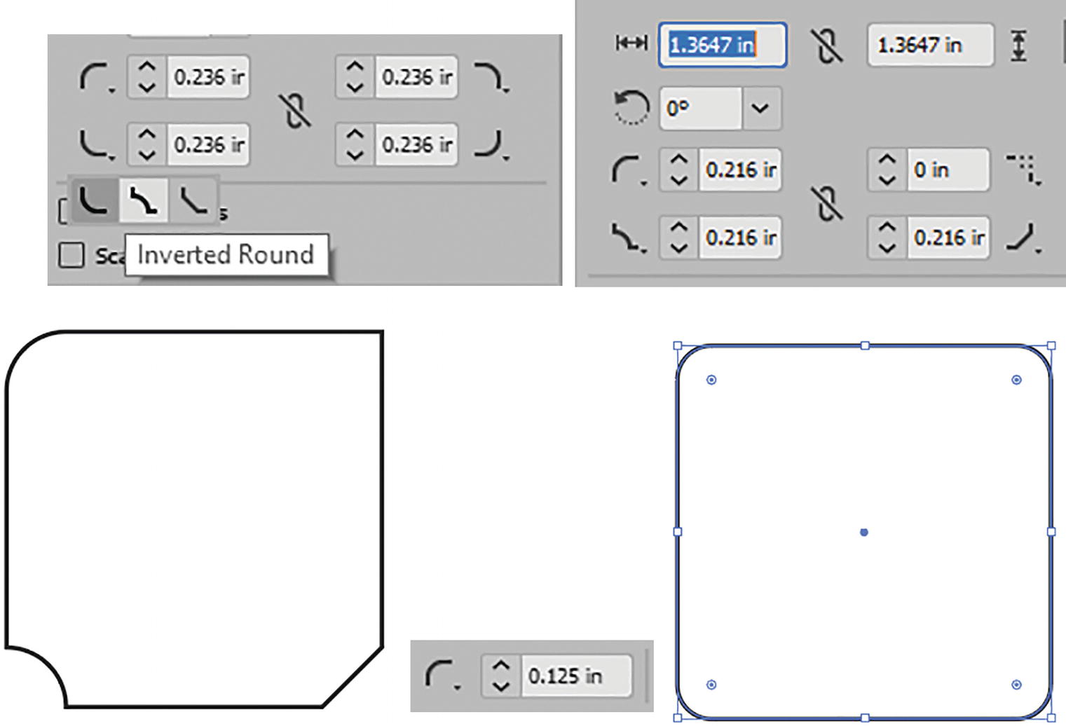
Adjusting the Corner Type options for rectangles and then resetting the sides
To reset all sides, click and choose one of the round corner type options in the Control panel and set the corner radius to make it all uniform. Then click on the link to link the radii for all corners.
In the Control panel use the Transform options to rotate and shear a rectangle
Upon shearing a rectangle, shape properties are lost
For information on the Isolate, Selected Object, and Select Similar Objects features, as well as editing similar shapes together, see my notes on these options in the Selection tool section earlier. Refer to Figure 2-98.
Additional options in the Control panel for all shapes
Use the Selection or Direct Selection tools to scale the entire path or points on a path while the shape is selected
Rectangles can also be rotated horizontally and vertically using the Properties panel, though if they are not on an angle, you will not notice the rotation. Refer to Figure 2-80.
Rounded Rectangle Tool
drag out a shape on the artboard;
hold down the Shift key as you drag if you want to create a rounded square;
press Alt/Option + Shift to drag the rounded rectangle or square from its center point; or
click somewhere on the Artboard with the tool to enter the Rounded Rectangle dialog box for the width and height. Then, choose with the link whether or not to constrain the width and height proportions, and set the corner radius. Click OK to commit. Refer to Figure 2-100.
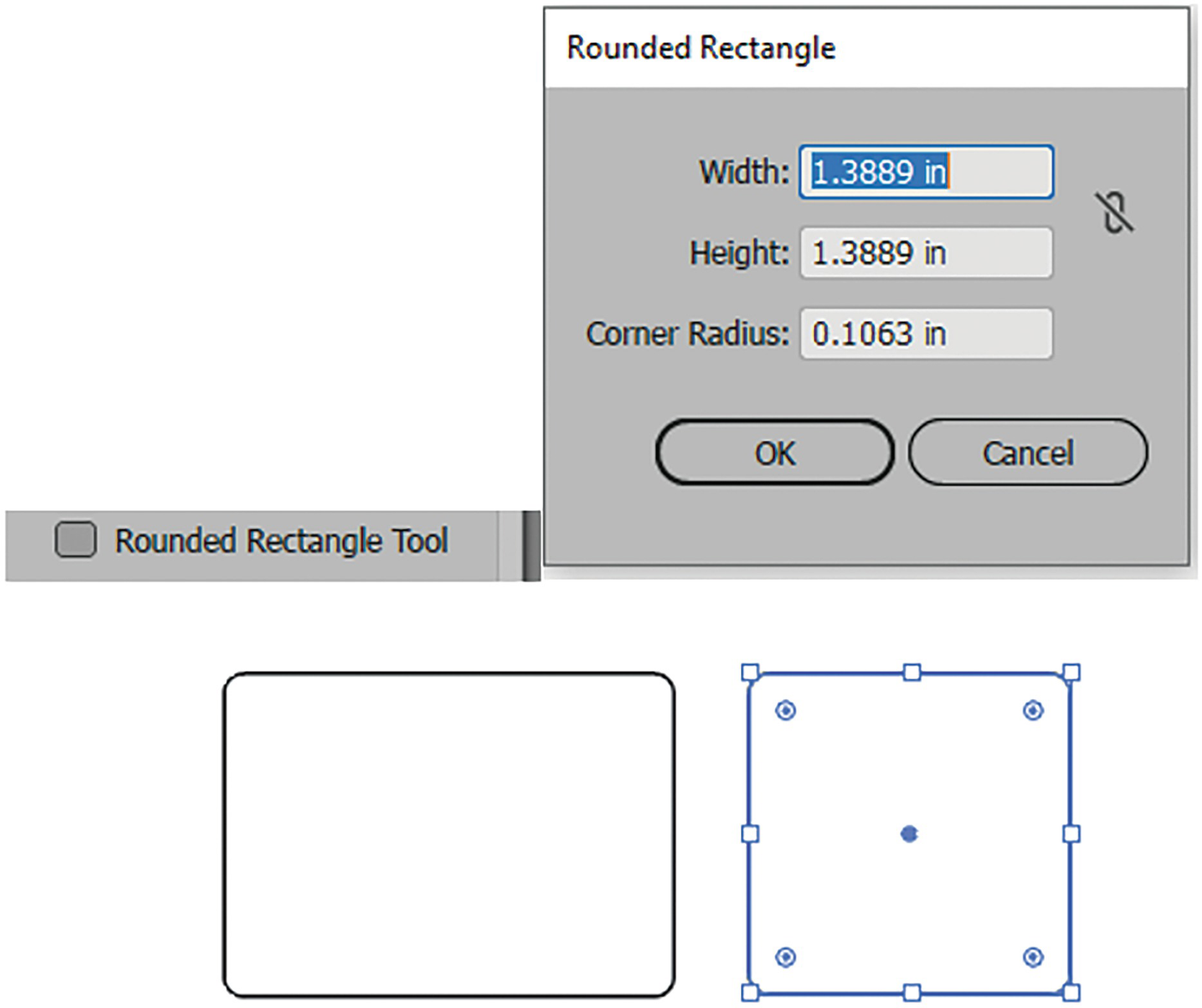
Rounded Rectangle tool, dialog box with settings, and various created rounded rectangles
Control Panel Options
The Control, Properties, and Transform panels have the same settings as the Rectangle tool, so you can refer to that section if you need more details.
Ellipse Tool (L)
drag out a shape on the Artboard;
hold down the Shift key as you drag if you want to create a circle;
press Alt/Option + Shift to drag the circle from its center point; or
click somewhere on the Artboard with the tool to enter the Ellipse dialog box to set the width and height. Then, choose with the link whether or not to constrain the width and height proportions. Click OK to commit. Refer to Figure 2-101.
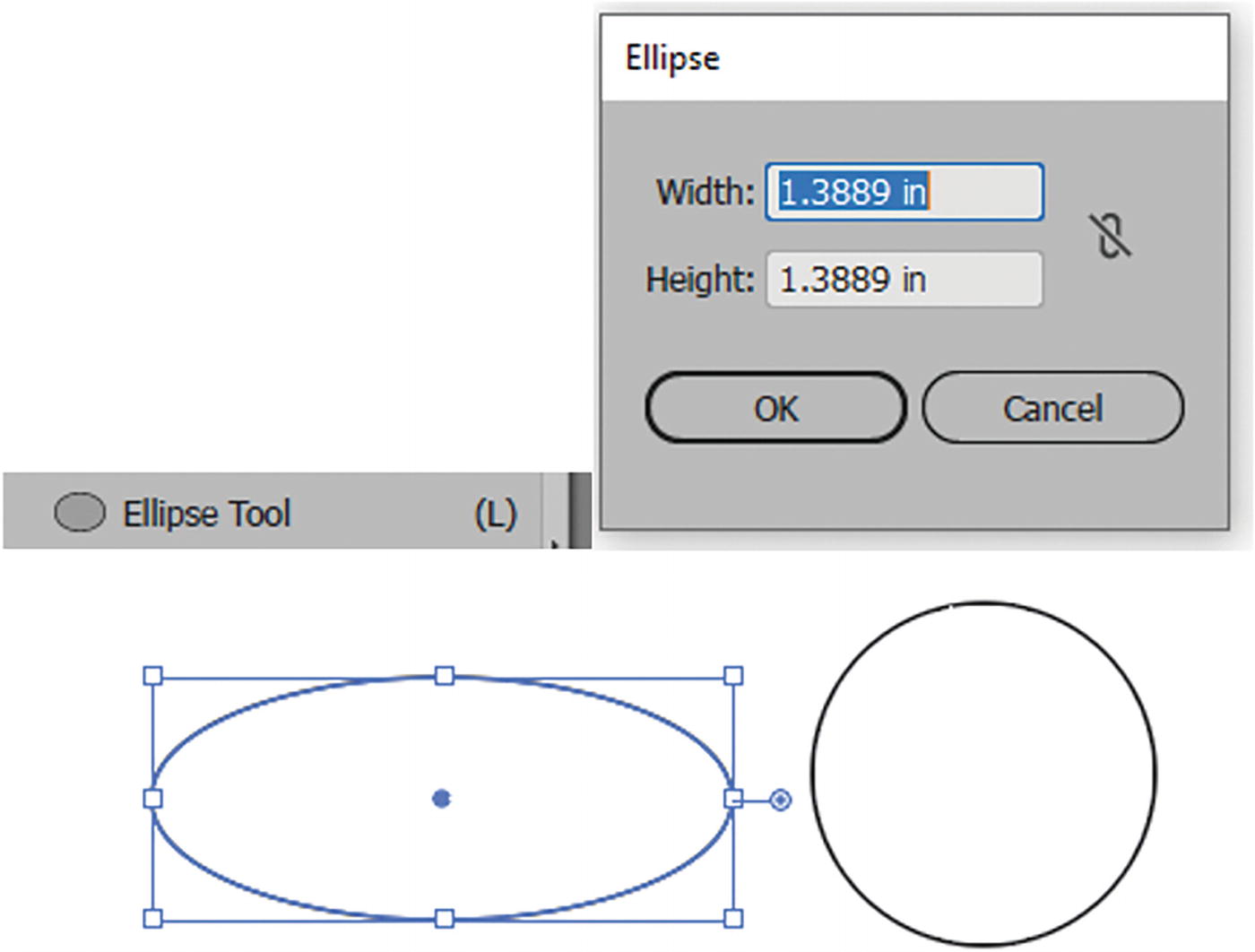
Ellipse tool, dialog box with settings, and various created ellipses
Control Panel Options

Additional Control panel settings for the selected ellipse
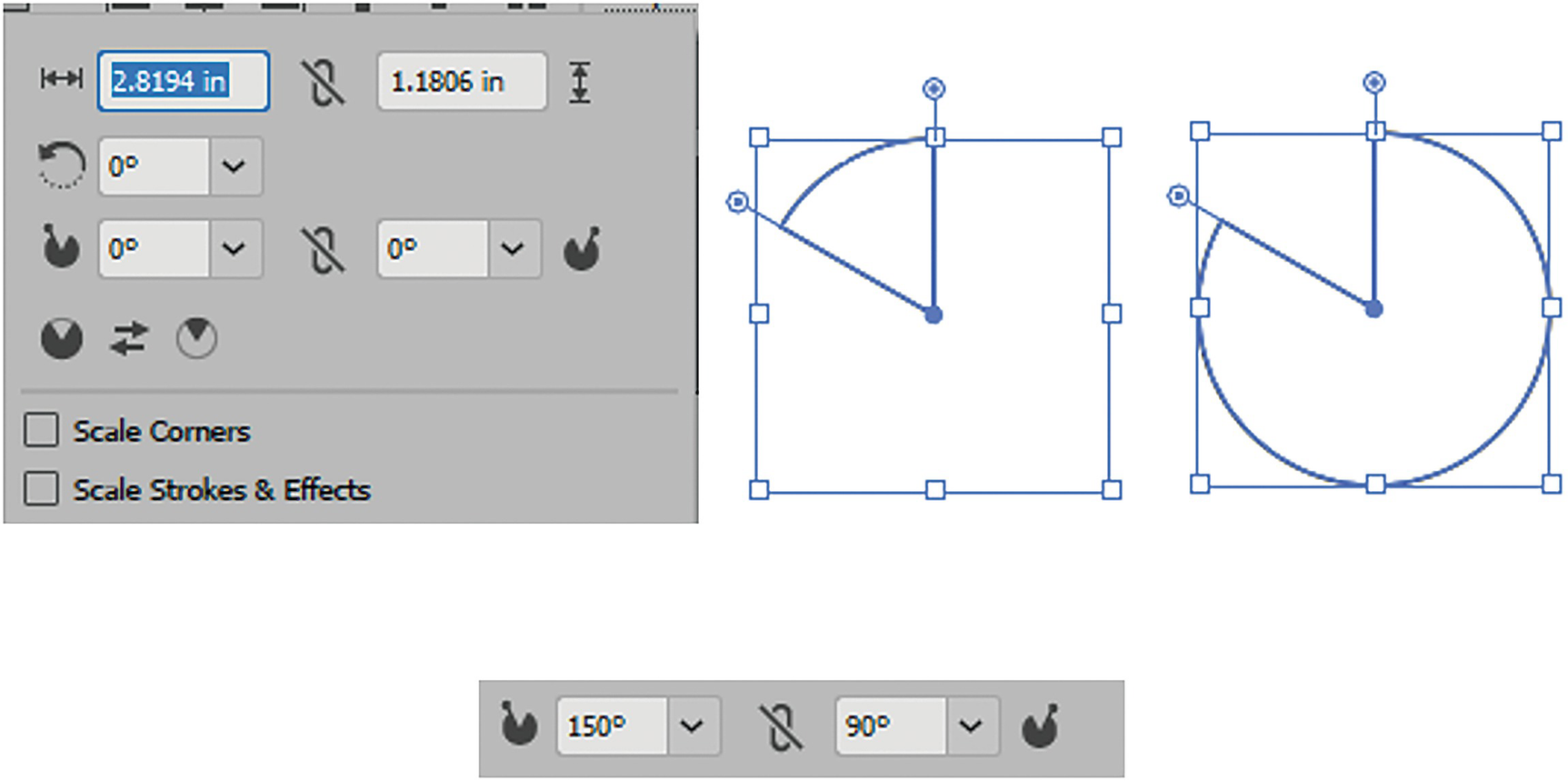
Shape properties options for the ellipse and the option to turn the ellipse into a pie by adjusting the start/end pie angle
You can use the handles on the ellipse to adjust the pie angle radius manually.
Additional Transform panel options
Polygon Tool
This is the same as using the Polygon tool and Triangle tool in Photoshop.
drag out a shape on the Artboard and rotate it at the same time. While dragging out the polygon you can use your up and down arrow keys to add or remove sides from the polygon;
hold down the Shift key as you drag if you want to create an equal-sided polygon with the lower face horizontal and no rotation;
press Alt/Option + Shift to drag the polygon from its center point; or
click somewhere on the Artboard with the tool to enter the Polygon dialog box to set the radius and sides (3–1000). Click OK to commit. Refer to Figure 2-105.
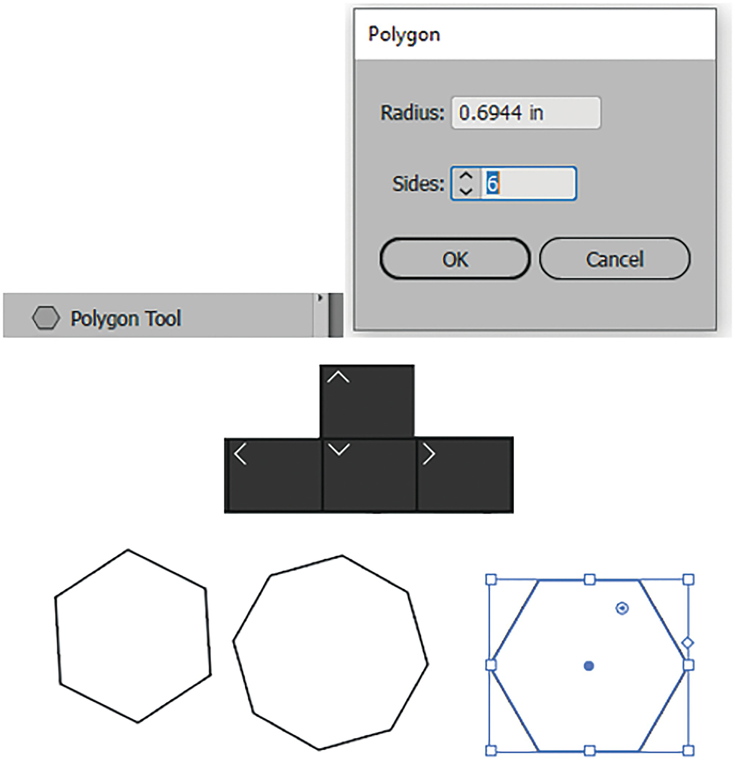
Polygon tool, dialog box with settings, and various created polygons when using the up and down arrow keys on the keyboard

Use the slider beside the selected polygon to add or remove sides, or the live corner widget to round the corners
Control Panel Options
In the Control panel and Properties panel you will find properties similar to those for the Rectangle tool, so you can refer to that section. However, I will point out the key differences for the Shape and Transform properties, as seen in the Control panel when you click on the name “Shape.”
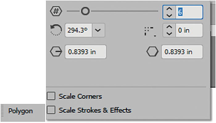
Shape properties options for the polygon
In the Control panel there are additional transform options
Use the Properties panel for easy access to settings for rotating or flipping your polygon vertically or horizontally. Also, use the Selection tool when you want to scale a disproportionate polygon. Refer to Figure 2-109.

Use the Properties panel to rotate and flip the polygon and the Selection tool when you want to scale the selected polygon
Star Tool

Toolbars panel Star tool
drag out a shape on the Artboard and rotate it at the same time. While dragging out the star you can use the up and down arrow keys to add or remove points from the star. Refer to Figure 2-111;
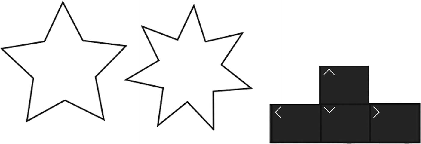
Various Star with multiple points that can be added as you drag on the star with your up and down arrow keys on your keyboard
hold down the Shift key as you drag if you want to create an equal-sided star with no rotation;
press Alt/Option + Shift to drag the star from its center point. You can also hold down the Ctrl/CMD key if you want a pointier star;
press Ctrl/CMD + Alt/Option + Shift + Drag, which will reset the star’s radius. Refer to Figure 2-112; or
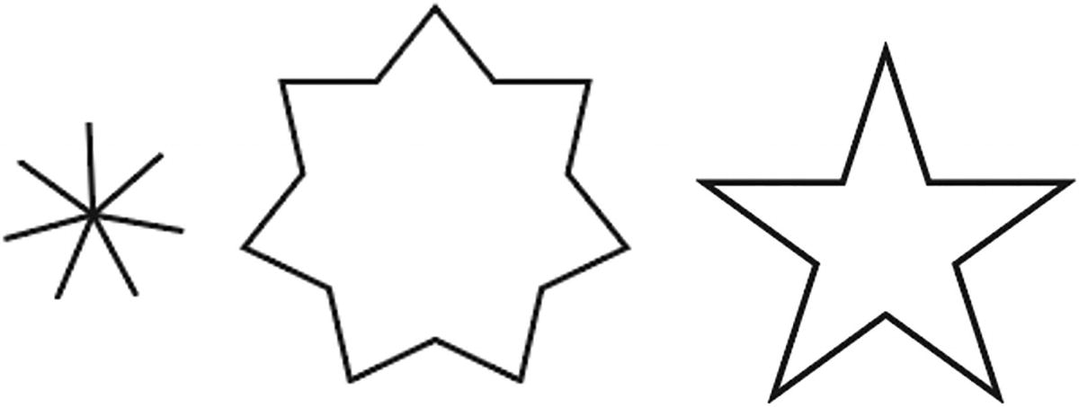
Make a pointy star or reset the star using additional keys on the keyboard while dragging out the shape
Or click somewhere on the Artboard with the tool to enter the Star dialog box for Radius 1, Radius 2, and Points (3–1000). Click OK to commit. Refer to Figure 2-113.
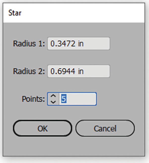
Star tool dialog box
Control Panel Options
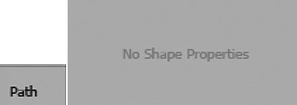
The star is a path, so there are no shape properties
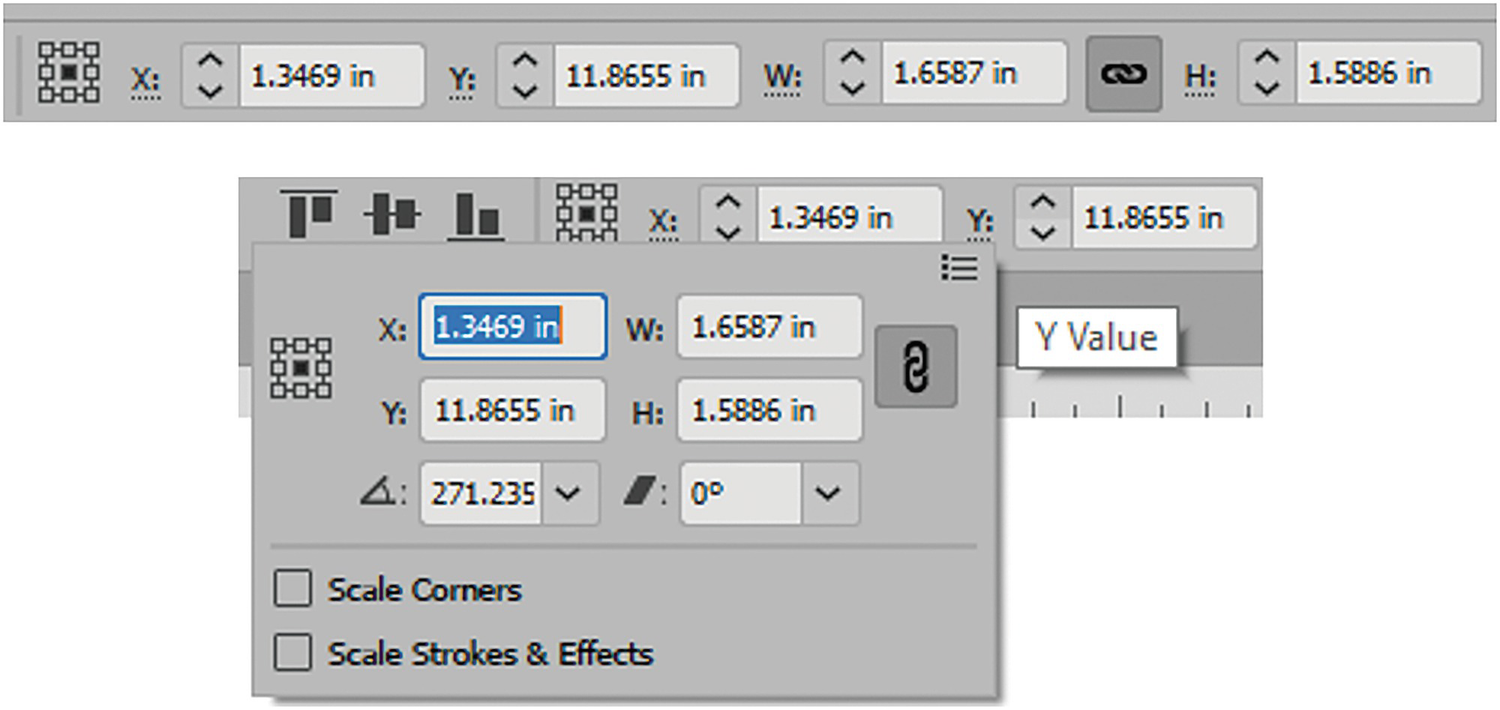
In the Control panel, there are additional transform options when X or Y is selected
Use the Direct Selection tool and Control panel to round the edges of the star
You can use the live corner widgets as well to round the star as you drag in or out.
The following tools I regard as more specialty tools for adding accents to your images.
Flare Tool
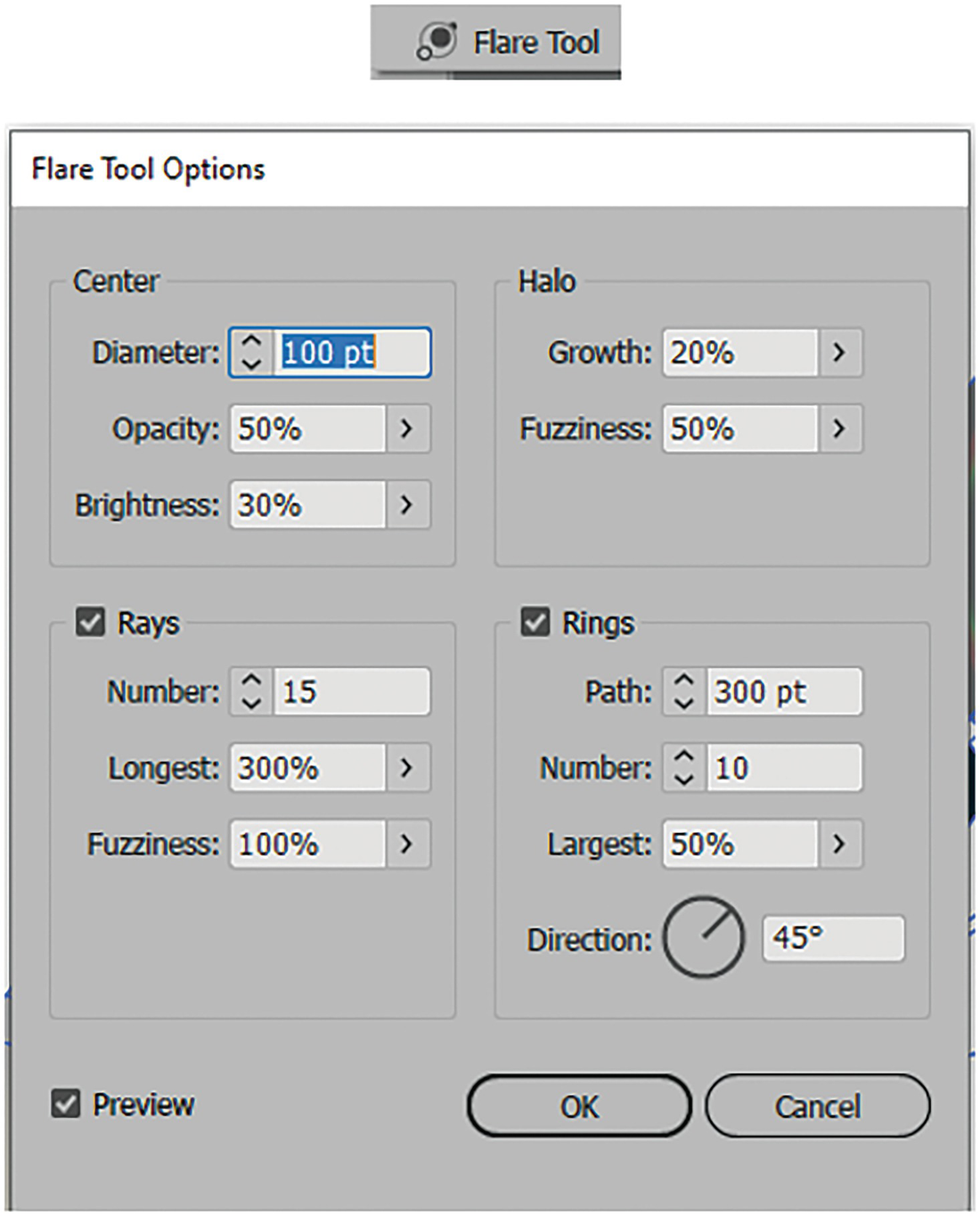
Flare tool and its options dialog box
With the preview check enabled, you can set such things as the following:
Center: Diameter in points, Opacity: 0%–100%, and Brightness: 0%–100%.Halo: Growth: 0%–300%, and Fuzziness: 0%–100%.
Then, enable or disable Rays, which are lines, and set the values for Number: 0–50, Longest: 0%–1000%, and Fuzziness: 0%–100%.
Lastly, you can enable or disable the Rings of additional circles and set the Path in points, Number: 0–50, Size of largest circles in ring: 0%–250%, and the Direction: 0°–359°. Then click OK. Refer to Figure 2-117.
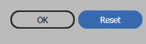
Hold down the Alt/Option key to access the Reset button in the dialog box

Flare on a blue background
While, at this moment, you may not see much of a use for a lens flare, you can use some of the gradients from them and store them in your Swatches panel for later use. We will look at gradients in more detail in Chapter 8.
Lens Flare Properties

Control panel settings for the selected lens flare

Control panel settings for the selected lens flare
Line Segment Tool ()
This tool is similar to the Line tool in Photoshop. This tool creates a single line segment, unlike the Pen tool, which is used to create and connect multiple segments.
drag out a line on the Artboard, while rotating it at the same time, and release the mouse;
hold down the Shift key while dragging when you want the line to be horizontal, vertical, or at a 45° angle, just like when you used the Pen tool;
press Alt/Option-drag when you want to scale the line out from its center. Refer to Figure 2-122; or
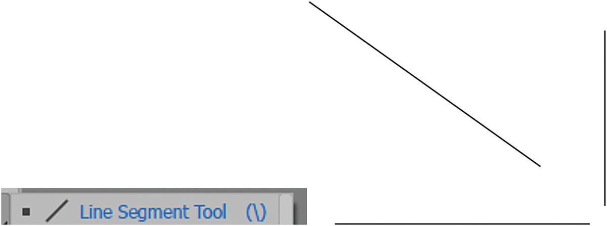
Line Segment tool and various lines drawn on the Artboard
click on the Artboard, with the tool selected, if you want to enter the Line Segment Tool Options dialog box. Here, you can set the length of the line, the angle (0°–360°), and whether to add a fill to the line. By default, this setting is disabled, as a single straight line would not have a visible fill. Click OK to commit. Refer to Figure 2-123.
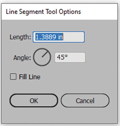
Line Segment Tool Options dialog box
Control Panel Options
You can set your line properties using the Control, Properties, or Transform panels. Most settings are the same as those for the Rectangle tool so you can refer to that section for more details. However, I will point out the key differences for shape and transform properties, as seen in the Control panel when you click on the name “Shape.”
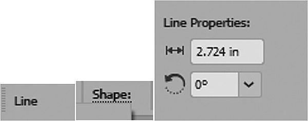
Control panel line shape properties options
Additional transform options when X or Y is selected
This tool is useful for grids and rows.
Later in Chapter 5 I will point out how you can add arrowheads to lines using the Stroke panel.
Arc Tool
This tool is similar to the Illustrator Line Segment tool except that it allows you to create a single arc, unlike the Pen tool, which is used to create and connect multiple segments.
drag out an arc on the Artboard, rotate it at the same time, and release the mouse, and the arc is on the Artboard;
hold down the Shift key while dragging when you want the arc to flip on the horizontal or vertical angle and the arc to be symmetrical;
press Alt/Option-drag when you want to scale the arc out from the center as you rotate. Refer to Figure 2-126; or
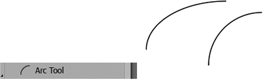
Arc tool and various arcs drawn on the Artboard
- click on the Artboard, with the Arc tool selected, if you want to enter the Arc Segment Tool Options dialog box. Here, you can set the length of the arc’s X-axis and Y-axis, and the reference point of where the arc will start upon dragging. Other additional settings include:
Type: Open or Closed path
Base along: X-axis or Y-axis
Slope: whether it is more concave or convex. Range is (-100,0,100).
Whether the arc should be filled with the current fill color in the Toolbars panel. By default, this setting is disabled as an arc line would not have a visible fill. Refer to Figure 2-127.
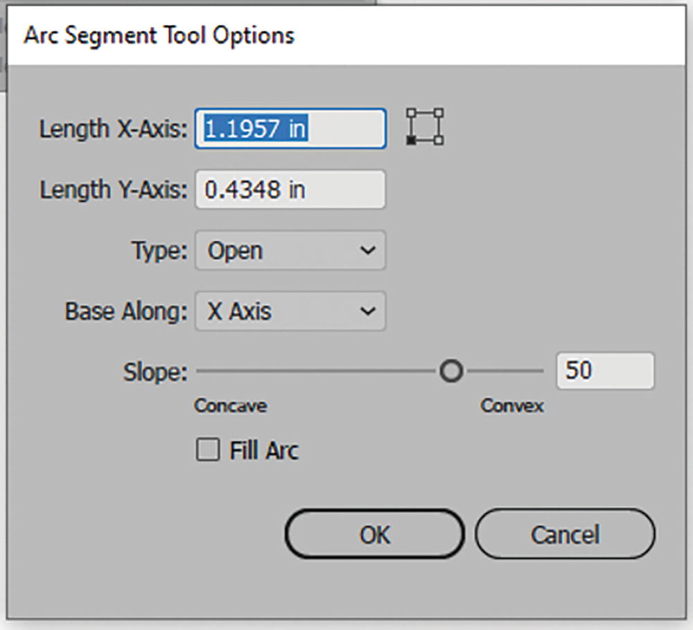
Arc Segment Tool Options dialog box
Click OK to Commit.
With the Arc tool, you can double-click on the tool in the Toolbars panel to see a preview window. This preview does not appear when you click with the tool on the Artboard. Refer to Figure 2-128.
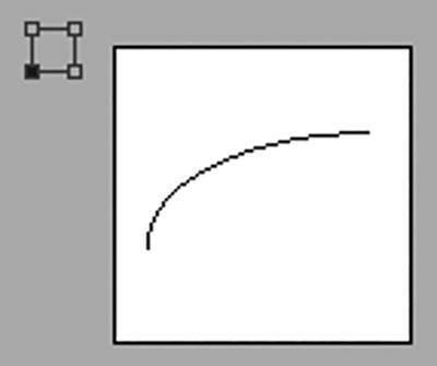
Additional preview option in the Arc Segment Tool Options dialog box
Control Panel Options
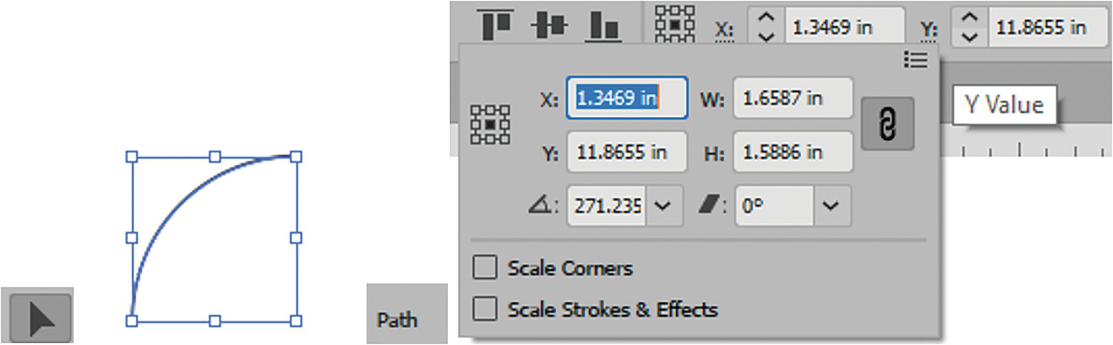
Additional transform options when X or Y is selected for the selected path
This tool is useful for creating grass, fur, or hair.
Spiral Tool
The Spiral tool is like the Arc tool except that it connects several arcs together to create a spiral snail shape.
drag out the spiral on the Artboard, rotate it at the same time, and release the mouse, and the arc is on the Artboard;
hold down the Shift key as you drag when you want the line to be symmetrical, on the horizontal plane, and with rotation constrained;
press Alt/Option-drag when you want a more simplified arc;
press Ctrl/CMD-drag out for a single arc segment. Refer to Figure 2-130;
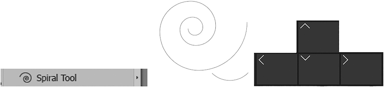
Spiral tool and a spiral on the Artboard that while dragging can be adjusted with the up and down arrow keys on the keyboard
as you drag, use the up and down arrow keys when you want to increase or decrease the number of segments; or
click on the Artboard to enter the Spiral dialog box and enter a Radius; Decay Rate: (5%–150%) the default is 80%; number of segments: 2–1000; and the style of either clockwise or counterclockwise. Click OK to commit. Refer to Figure 2-131.
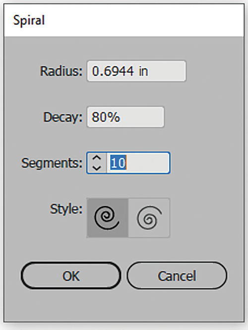
Spiral tool dialog box
Control Panel Options
Like the arc, no additional shape properties are found in the Control, Properties, or Transform panels as the spiral is regarded as a path. However, you can use the Control, Properties, or Transform panels to adjust basic settings, like when you created a path with the Pen tool and selected the path with the Selection tool.
This tool is good for creating snail shells or the stylized idea of wind or steam and is useful for text on a path, which we will see in Chapter 10.
Rectangular Grid Tool
drag out the grid on the Artboard, release the mouse, and the grid is on the Artboard;
hold down the Shift key while dragging when you want the lines to be symmetrical and evenly spaced;
press Alt/Option + Shift + Drag when you want to drag out the grid from its center. Refer to Figure 2-132; or
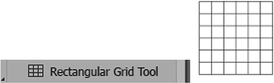
Rectangular Grid tool and a Rectangular Grid on the artboard
click on the Artboard with the tool and enter the Rectangular Grid Tool Options panel. You can set the default size for width and height and the reference point from where the rectangle is dragged. You can also set the number of horizontal dividers (0–999) with skew setting from bottom to top (-500,0, 500%), and vertical dividers (0–999) with the skew setting from left to right (-500,0,500%). Refer to Figure 2-133.
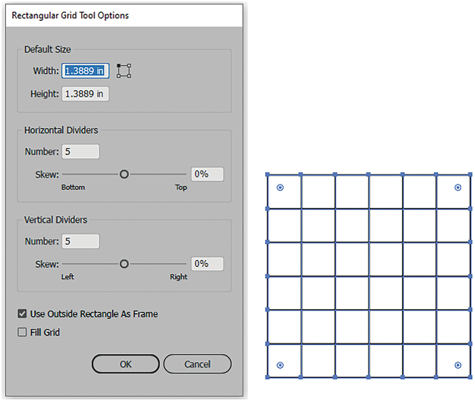
Rectangular Grid Tool Options dialog box next to a selected rectangular grid with live corner widgets
Enable Use Outside Rectangle As Frame when you want a border around the grid and Fill Grid if you want the current fill in the Toolbars panel inside, In this case it is disabled and the fill is set to none. Click OK to commit. Refer to Figure 2-133.
Control Panel Options

The rectangular grid is considered a group object
Parts of grids can be modified with the Selection tool, Direct Selection tool, and Group Selection tool
You will see an example of the Rectangle Grid tool being used in Chapter 13 to add perspective to a building to give the effect of windows on skyscrapers.
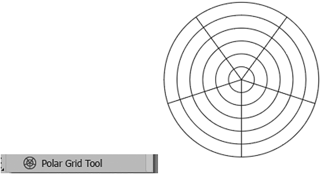
Polar Grid Tool
The last shape tool in Illustrator is the Polar Grid tool. It creates a series of lines and circles and arranges them in a grid-like spider-web pattern.
drag out the grid on the Artboard and release the mouse;
hold down the Shift key while dragging when you want the circle to be symmetrical and the lines evenly spaced;
press Alt/Option + Shift + Drag when you want to drag out the grid from the center. Refer to Figure 2-136; or
Polar Grid tool and a Polar Grid on the artboard
click on the Artboard with the tool and enter the Polar Grid tool options. You can set a default size for width and height, and the reference point from which the polar grid is to be dragged. Number of concentric dividers can be set (0–999), with the Skew setting from In to Out (-500,0,500%), as can the number of radial dividers (0–999), with the Skew setting from Bottom to Top (-500,0,500%). Refer to Figure 2-137.
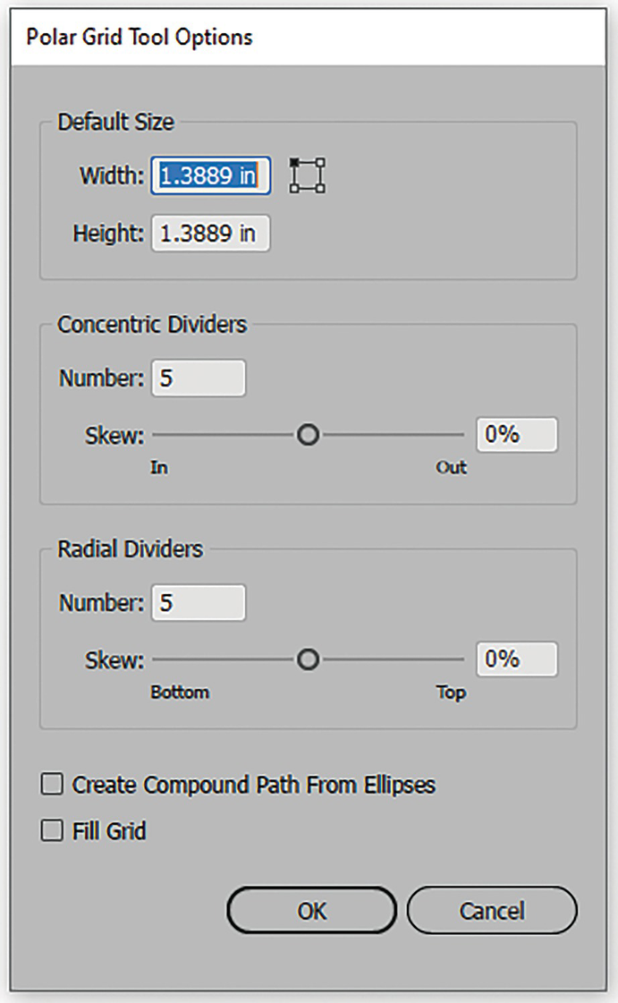
Polar Grid Tool Options dialog box
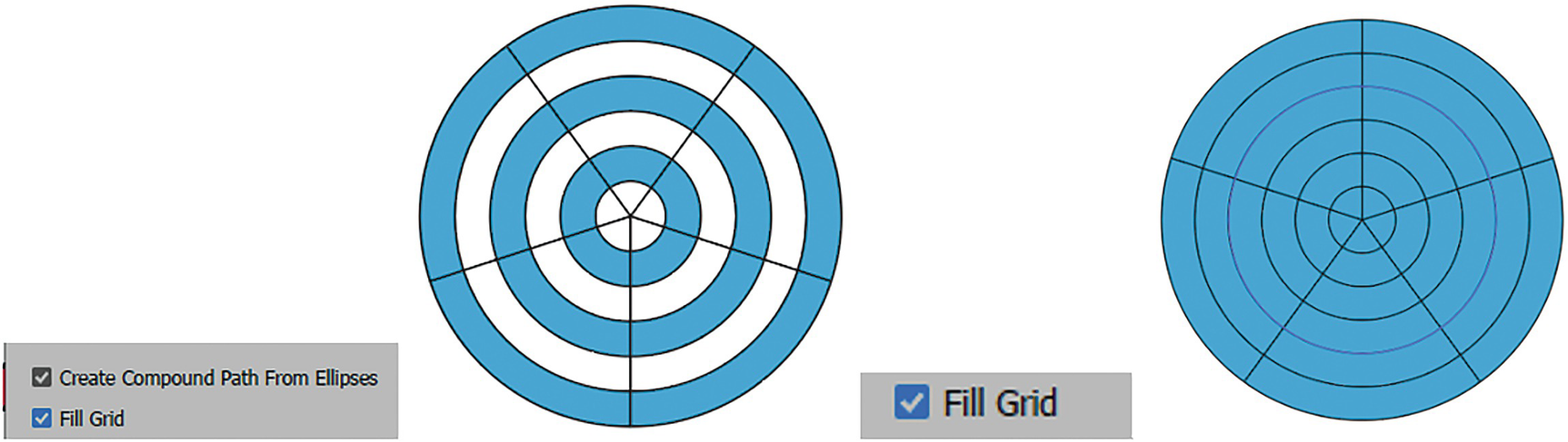
Polar Grid with a setting of Create Compound Path From Ellipses and Fill Grid, and the other with just the setting of Fill Grid
Control Panel Options
No additional shape properties are found in the Control, Properties, or Transform panels. Like the rectangular grid, this is considered a group shape, and you can refer to the Rectangular Grid tool for more details.
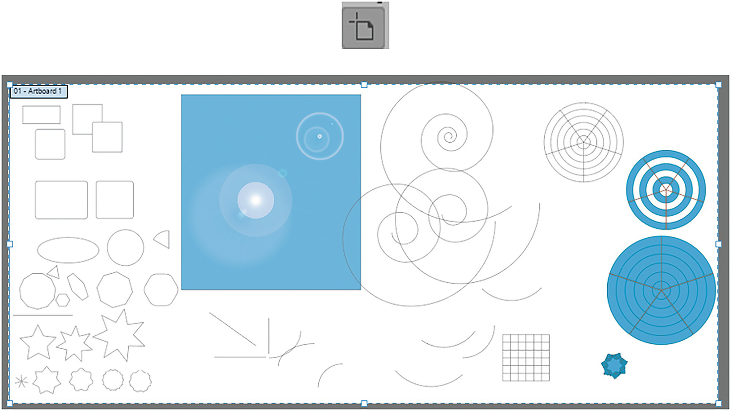
If you are dragging out a shape with one of the Shape tools, make sure to experiment by holding down the tilde key (~). Rather than Alt/Option-dragging to make copies, this creates multiple shapes all at once and rotates and scales copies at the same time. Refer to Figure 2-139.

Use the tilde key when dragging out a shape to create a unique pattern
Tips for Practicing with the Artboard and Layers Panel
The Artboard tool and selected Artboard
We will practice using this tool in the next project, and I will explain how to expand the Artboard.
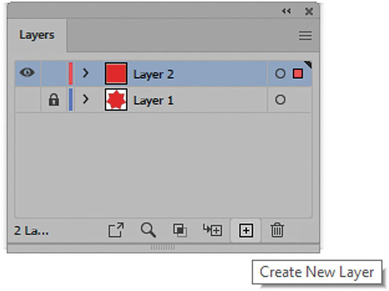
Layers panel with shapes on separate layers
We will be using layers in the next project to keep our shapes organized and neat.
Align Panel to Align Shapes
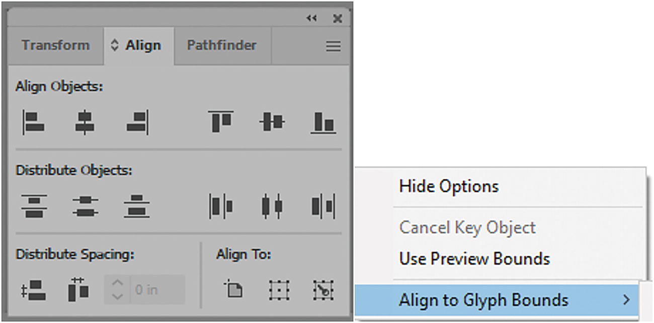
Align panel and its menu
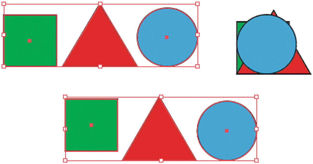
Shapes arranged using the Align panel
You can also adjust the distribute spacing vertically or horizontally by a set space amount with a key object and align to Artboard, selection, or key object. Refer to Figure 2-142.
Use the Pathfinder to Edit Shapes
In Chapter 3, in Photoshop, you used the Properties panel and Pathfinder options to edit shapes. In this chapter, you can use the Pathfinder panel as well.
Bring to Front: Shift + Ctrl/CMD + ]
Bring Forward: Ctrl/CMD + ]
Send Backward: Ctrl/CMD + [
Send to Back: Shift + Ctrl/CMD + [
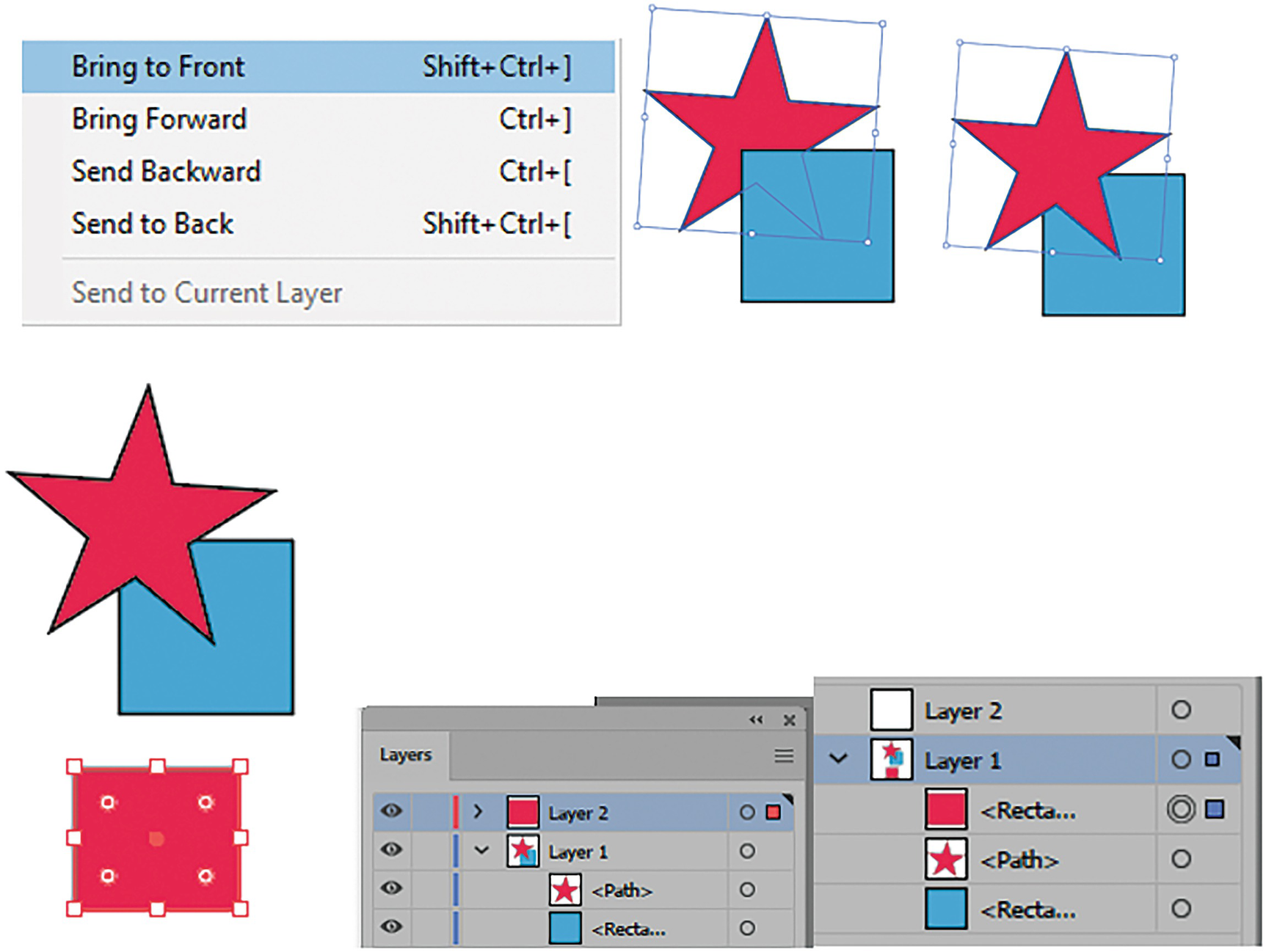
Use the Object menu to arrange shapes on a selected layer and its sub-layers. Use the Layers panel to move objects from one layer to another
Knowing these key combinations is very useful when you want to move selected shapes above or below each other on a layer, without having to use the Object menu each time. Note, however, that this only works within the layer and sub-layer. In situations where you must move an item above or below onto another layer, while the item is selected use the Layers panel to drag the selected item—represented by a colored square on the right—to a new layer.
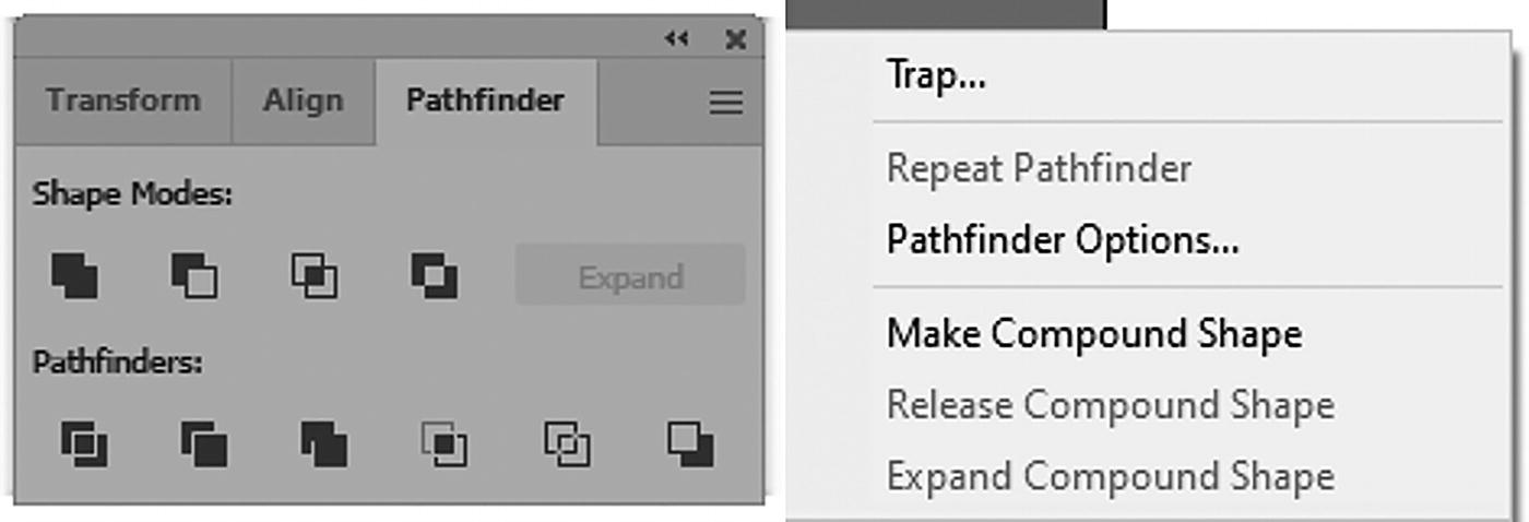
Pathfinder panel and its menu

Two shapes, and then they are Shift + Click selected with the Selection tool
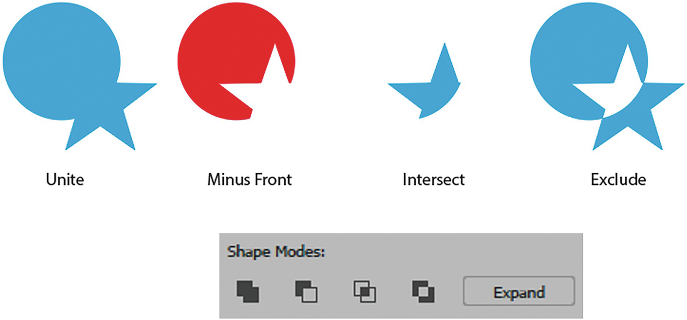
Example of the Pathfinder panel shape modes and the Expand button
And you only commit when you click the Expand button in the Pathfinder panel.
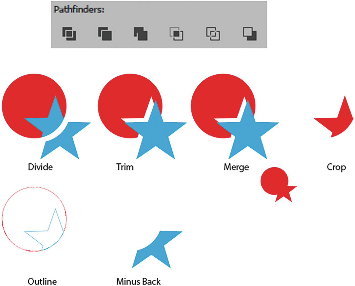
Examples of the Pathfinder panel options. Merge behaves differently when the colors are the same versus different
You can see these Pathfinder examples in more detail in the file two_blends.ai, and see Chapter 10 for an example when working with type.
To create live, editable shapes you can use the Effect ➤ Pathfinder menu. See Chapter 11 for more details on that topic. For certain Pathfinder settings, this is a better and less destructive option.
Make sure, at this point, to save any of your practice projects that you have created so far.
Project: Blowing in the Wind, Part 1
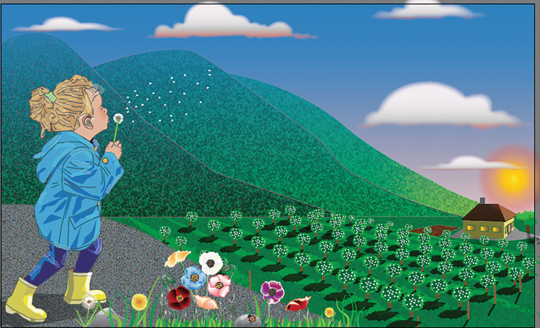
An illustration of a young girl at a farm blowing dandelion seeds over a field
To start, create a practice file by going to File ➤ New and creating a preset, as you did in Chapter 1.
Or, if you want to follow along, you can save a copy of my file Landscape1_start.ai.
Setting the Size of the Artboard
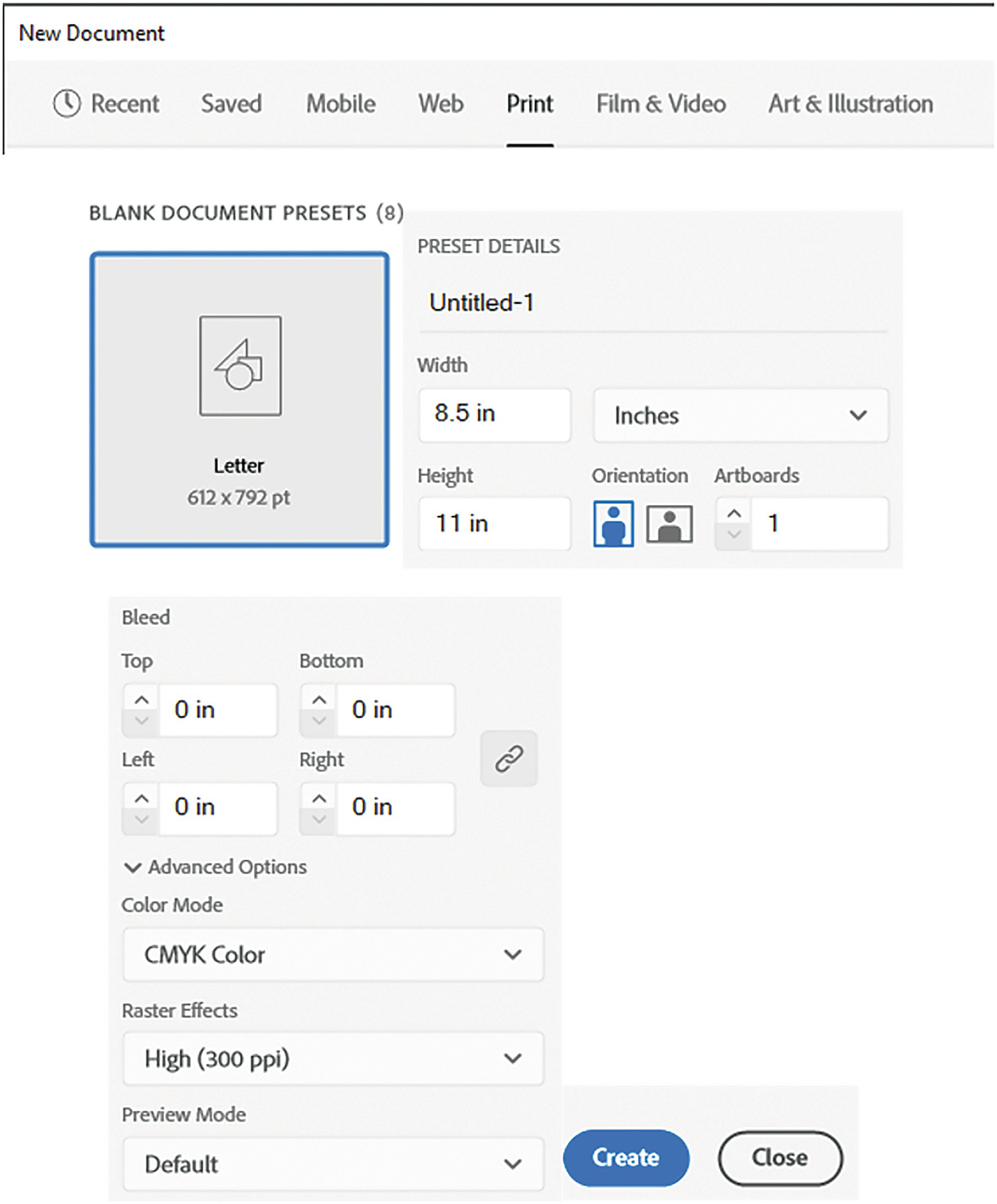
Preset settings in New Document dialog box

Blank document created from preset settings
At this point, you should make sure that you View ➤ Rulers ➤ Show Rulers (Ctrl/CMD+R). They should be set to the increments of inches if you set this earlier when you created your document. Also, make sure that your View ➤ Smart Guides (Ctrl/CMD+U) are enabled as well. This will assist us as we add guides and shapes. Refer to Figure 2-152.
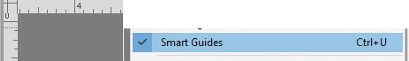
Rulers and Smart Guides should be enabled
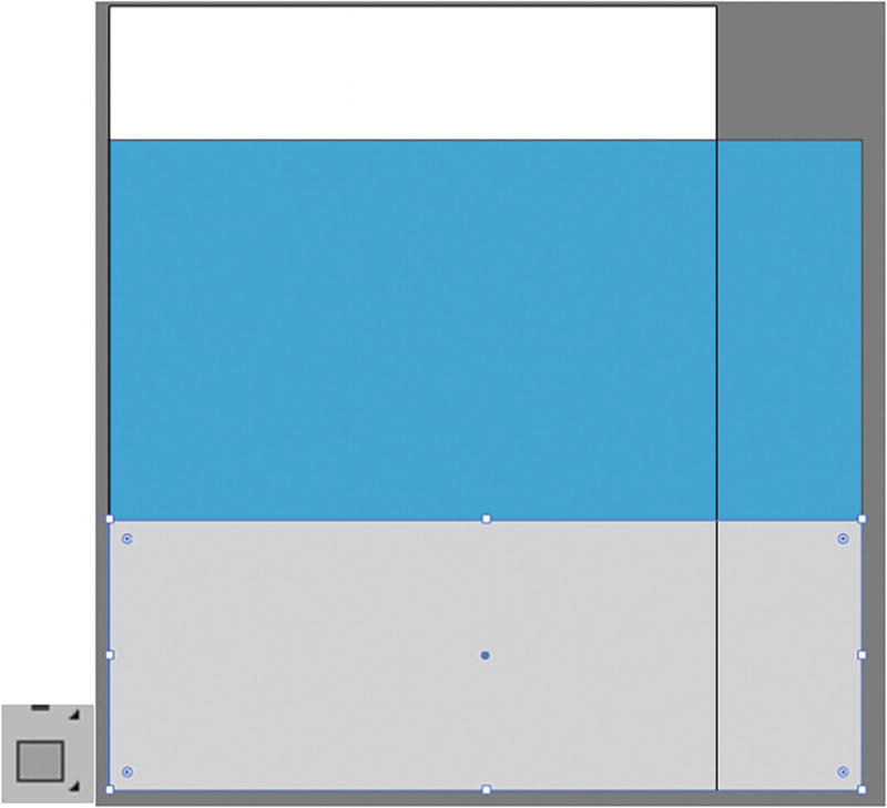
Using the Rectangle tool to draw the ground and sky and then realizing the Artboard is not wide enough
Toolbars panel Artboard tool
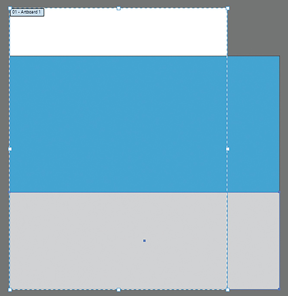
Artboard Editing mode
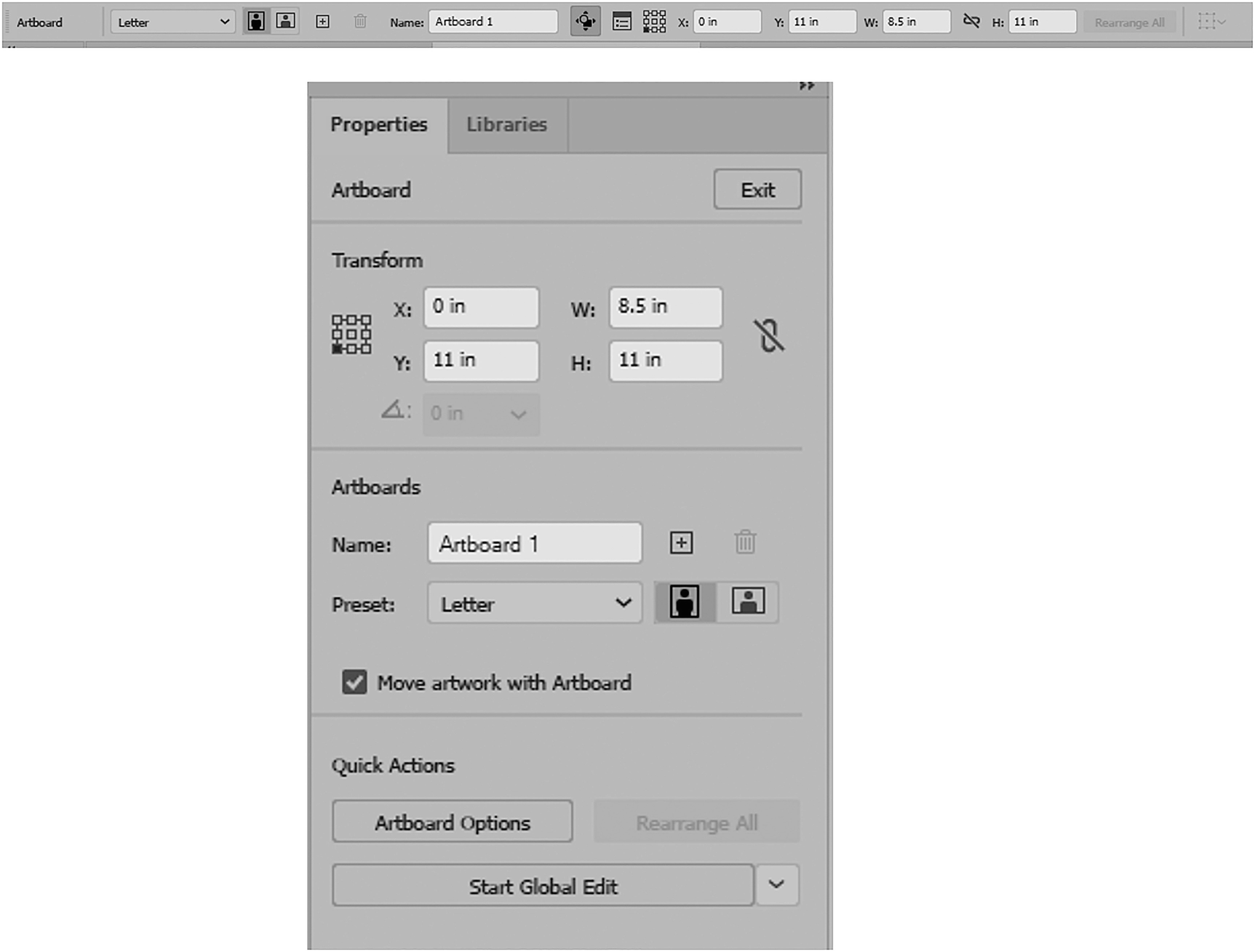
The Control and Properties panels while in Artboard Editing mode
In this case, I’ll use the Control panel to alter the size.
Control panel with Artboard settings

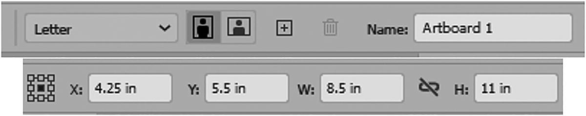
Setting the Artboard to Landscape but with an incorrect Artboard reference point
If you made this mistake at this point, you can Edit ➤ Undo (Ctrl/CMD+Z) and try again.
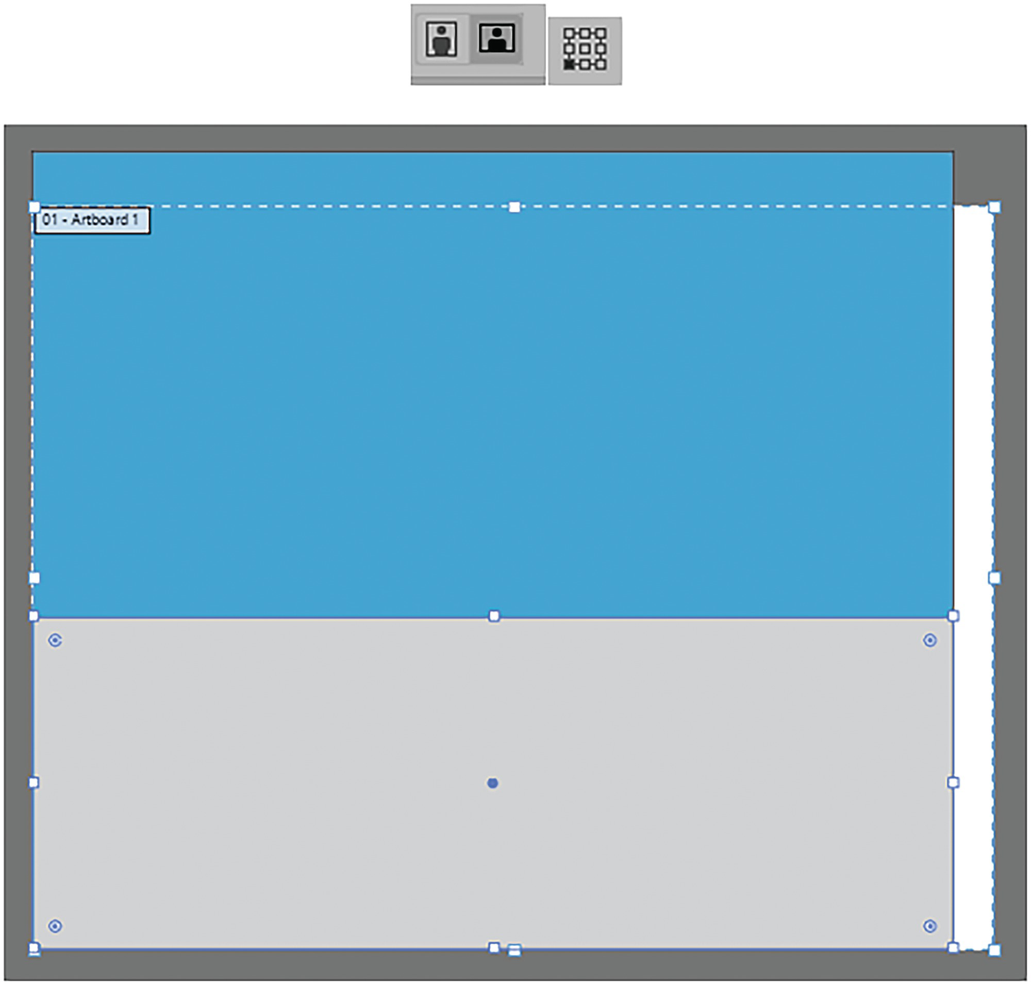
Setting the Artboard to Landscape but with a correct Artboard reference point in the lower left
However, if you want to have a wide landscape, you need to extend the Artboard a bit more on the right; the preset of Letter is not going to work.
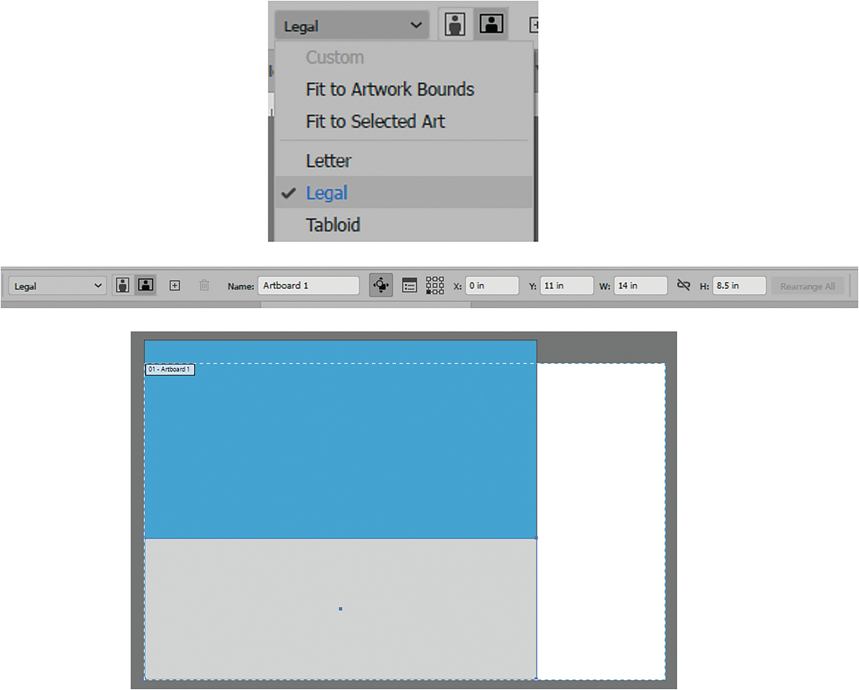
Setting the preset to Legal for the Artboard. Settings are W: 14 in and H: 8.5 in because it is landscape

Additional Artboard mode settings
If you are working with multiple Artboards, you can use other buttons in the Control panel that appear to add, delete, move, or copy Artboards, as well as additional Artboard options. You can also arrange all Artboards and align them.
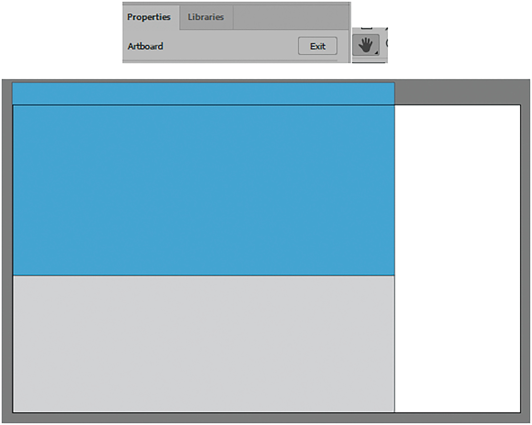
Exiting Artboard mode using the Properties panel or the Hand tool
I then save the document at this point as Landscape1_start.ai. In your case you can save the file with your initials on it. Or refer to my copy of the file if you want to follow along.
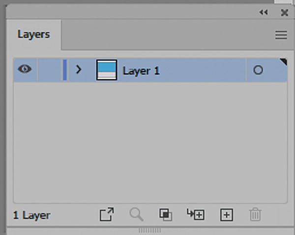
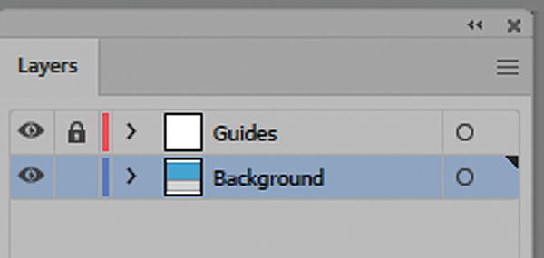
Layers panel with a single Layer 1
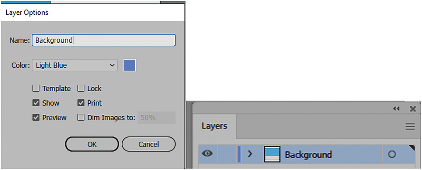
Use the Layer Options dialog box to rename the layer and view its options
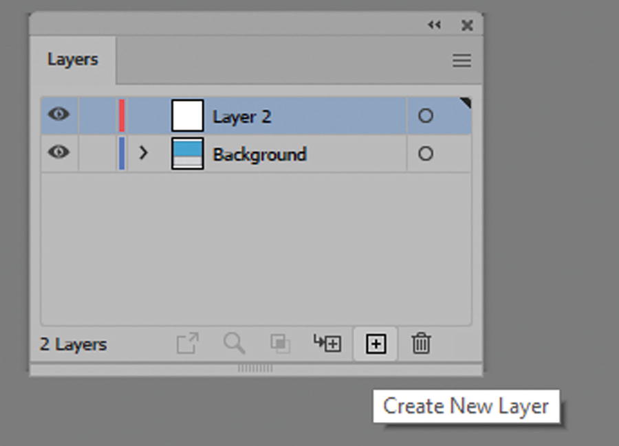
Create a new layer above the Background layer
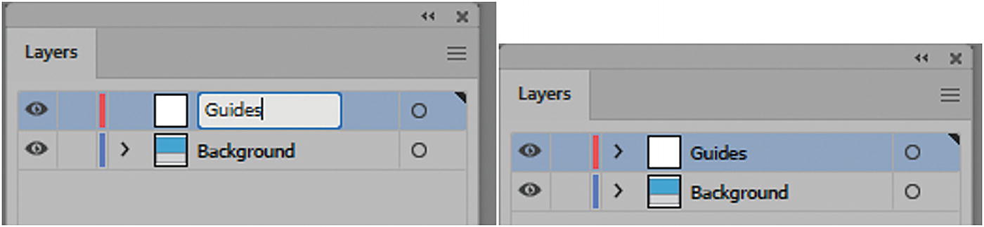
Rename the layer Guides and then click beside the name to confirm it
Then, click outside the text area to the right to confirm the name.
On this layer, because my rulers are active, I drag down two horizontal guides from the rulers using my Selection tool.
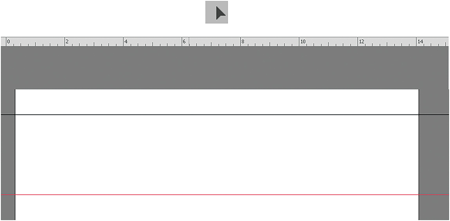
Use the ruler to drag down two horizontal guides
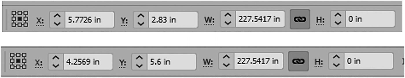
Use your Control panel while a guide is selected to adjust your settings
In this example your X value, width (W) value, and height (H) value may be different than mine, but they do not need to be the same, as only the Y value is needed.
Use the Layers panel to lock the Guides layer
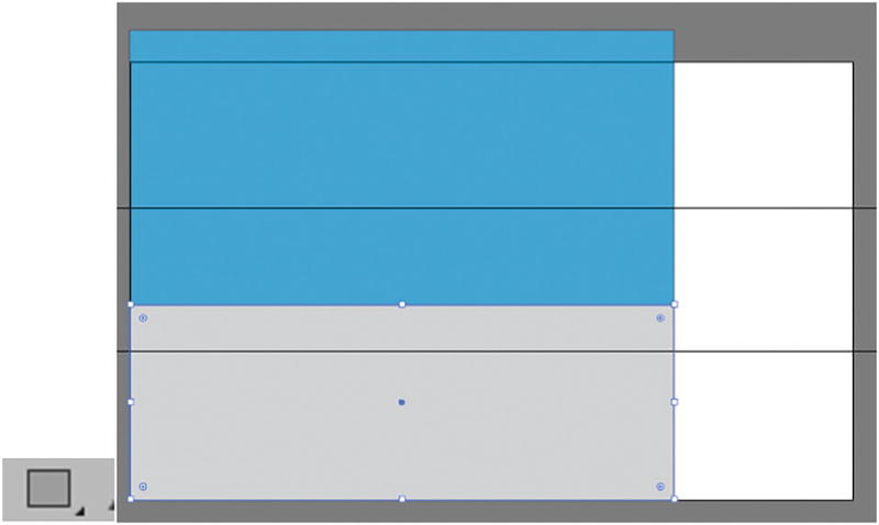
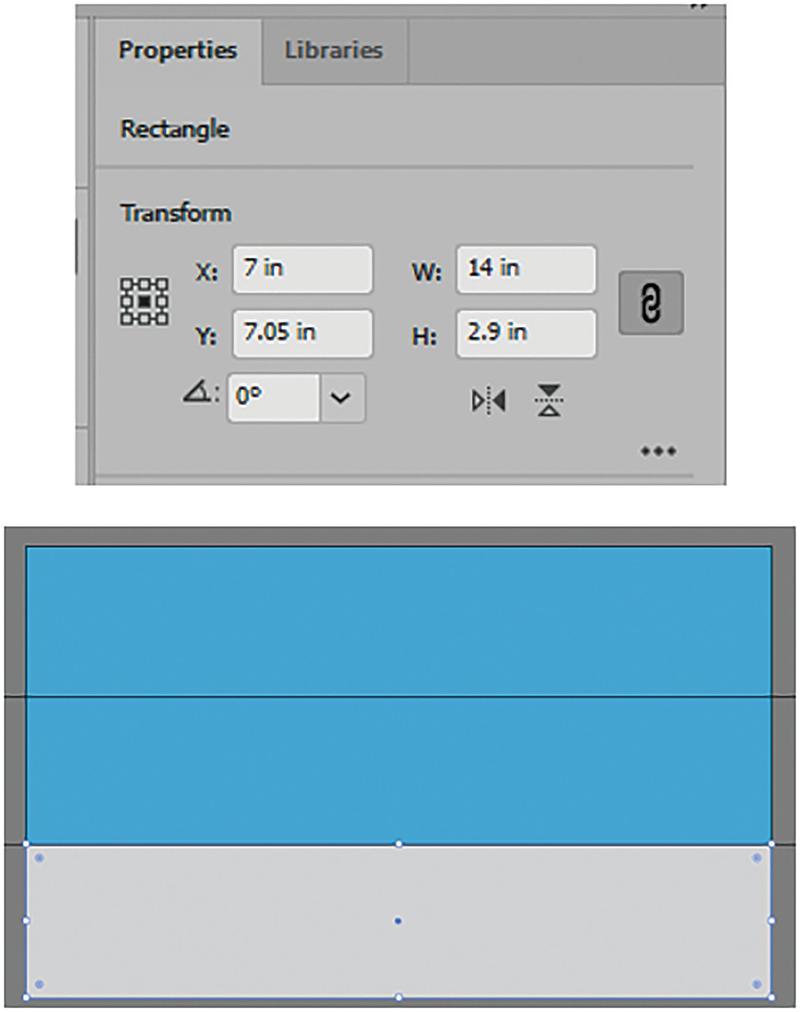
Use your Rectangle tool to drag out two rectangles for the ground and sky, if not done already
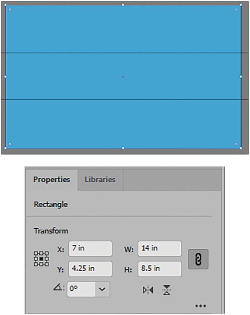
Use the Properties panel to set the X, Y, W, and H for your rectangle
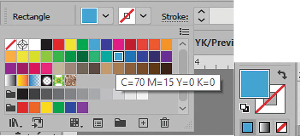
Use the Control panel to set the fill and stroke colors for the sky, as seen in the Toolbars panel
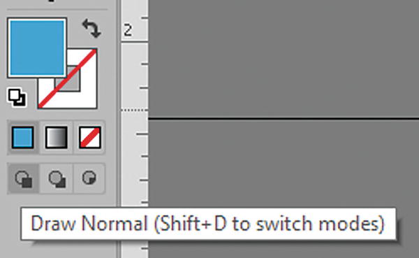
Make sure as you draw additional shapes that the Toolbars panel is set to Draw Normal
Make sure that your Toolbars panel is set to Draw Normal mode and not Draw Behind or Draw Inside.
Use the Rectangle tool to draw the ground if you have not already done so
If you have already drawn the ground and it is behind the blue sky, then just select the blue rectangle with your Selection tool and choose Object ➤ Arrange ➤ Send to Back.
Use the Properties panel to set the X, Y, W, and H for your rectangle for the ground
In your View menu, if your Smart Guides are on, the rectangle should snap to the guides.
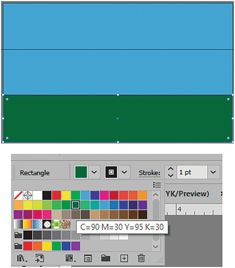
Use the Control panel to set the fill color for the ground
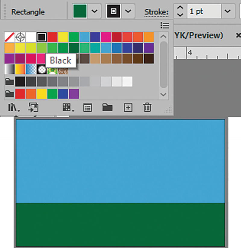
Use the Control panel to set the stroke color for the ground
The stroke gives us a light boundary line for the horizon.
At this point, while you are drawing the basic shapes, do not be concerned about realism in colors. Later, in Chapter 8, we will improve many of the colors using multiple gradients and transparencies. For now, working with solid colors is best.
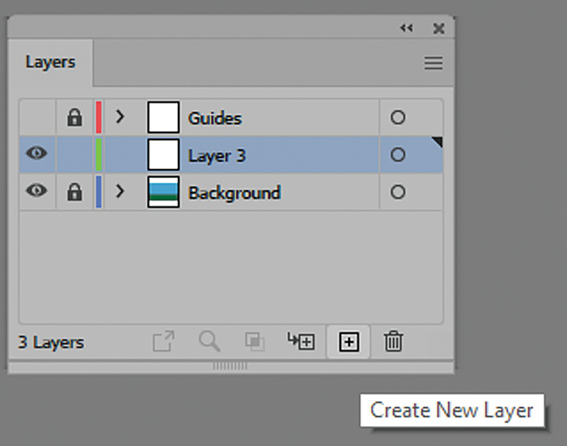
Lock the Background layer and create another layer above it
Working with Template Layers and Locked Layers
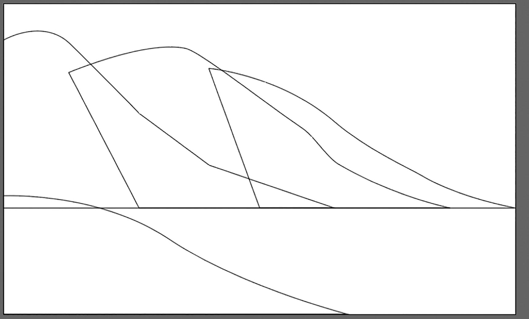
Now we need to add the mountains and foreground. You can draw them using the Pen tool, which can be practiced over a template layer or a locked layer, which I have created in the file mountains_foreground_trace.ai.
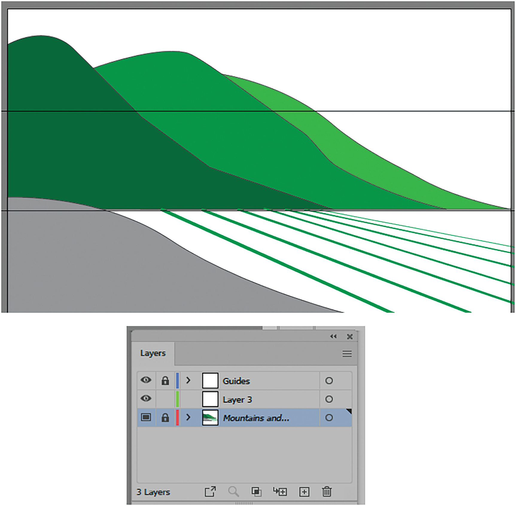
In the Layers panel, view the template layer
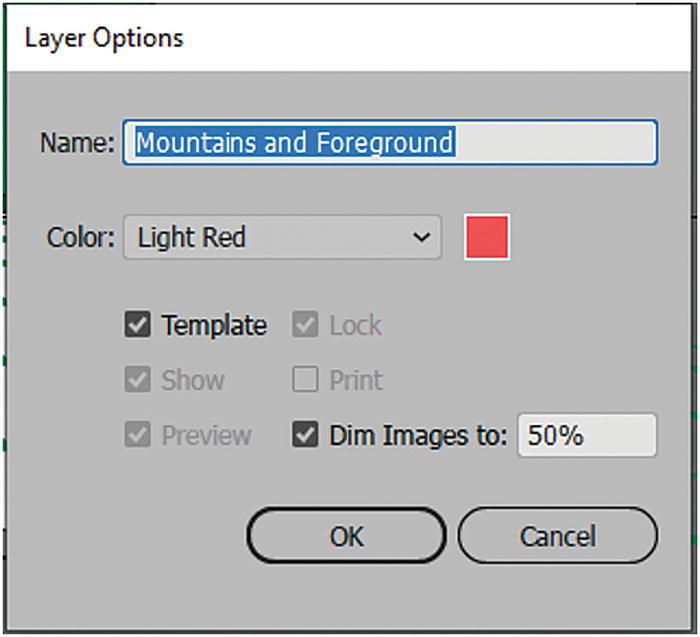
Layer Options dialog box with template settings
Pen tool
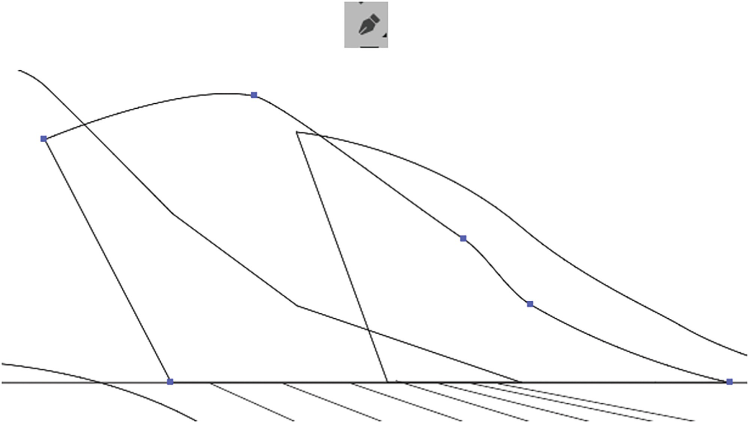
Use the Pen tool to trace over the nearest mountain to create a path with points
Change the stroke to an easy-to-see color before you use the Pen tool by clicking on a swatch color
Use the Direct Selection tool to modify paths; your Zoom tool to get a closer view; and your hand tool to move about without disrupting the path
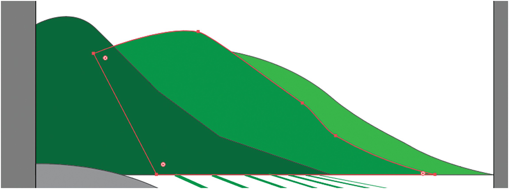
Knowing where to stop the path can be tricky when it goes behind another part of the image
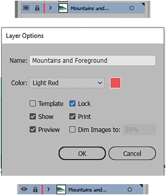
Reset your layer’s Layer Options so that you can easily view my paths to practice tracing
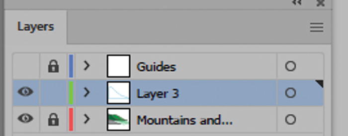
Return to Layer 3 to continue tracing
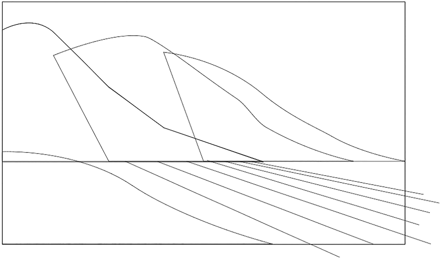
Using Outline Mode allows you to see all the paths you need to trace
Use your Pen tool to trace the middle mountain
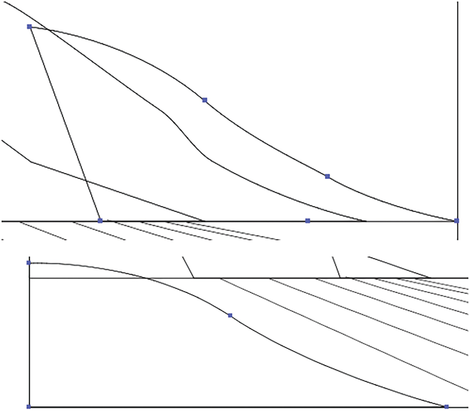
Use the Pen tool to trace the mountain on the right and the foreground area
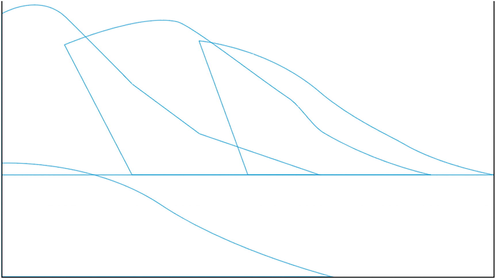
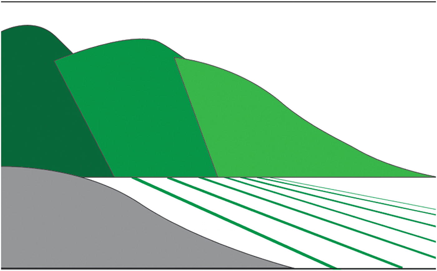
Here are how the traced areas should appear with the cyan stroke and fill of none
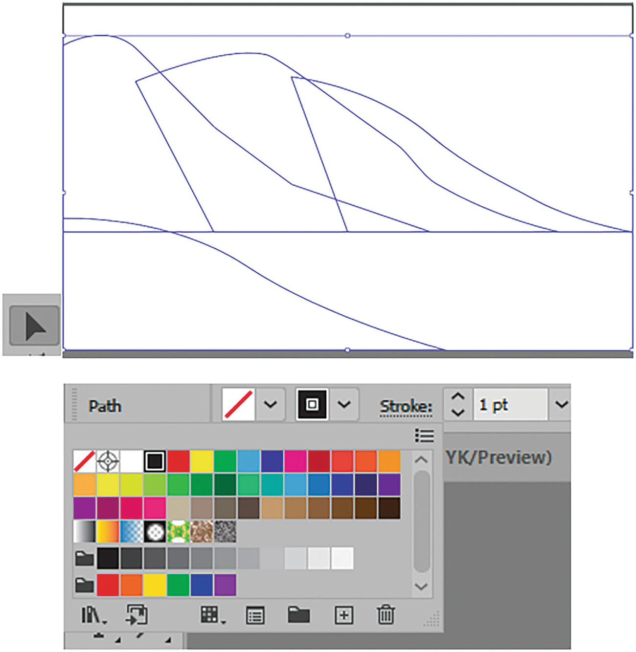
Shift + Click to select each path and then use the Control panel to set the stroke to black
How the paths appear as a black stroke
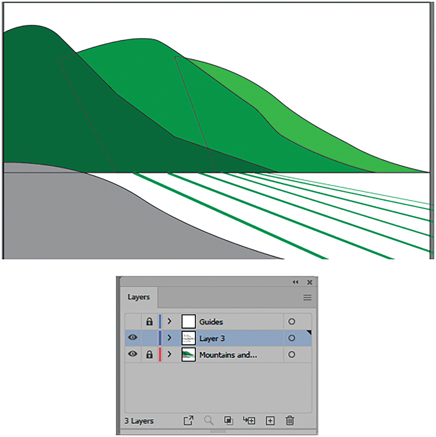
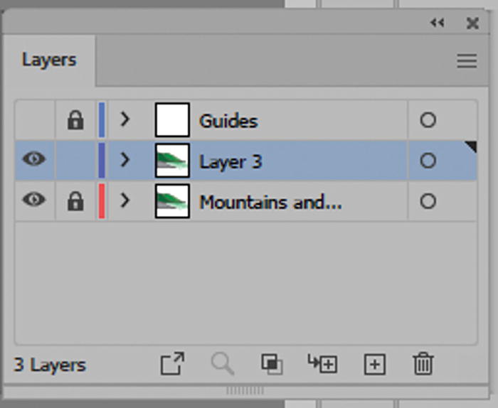
Make sure you have your Mountains and Foreground layer visible and Layer 3 selected in the Layers panel
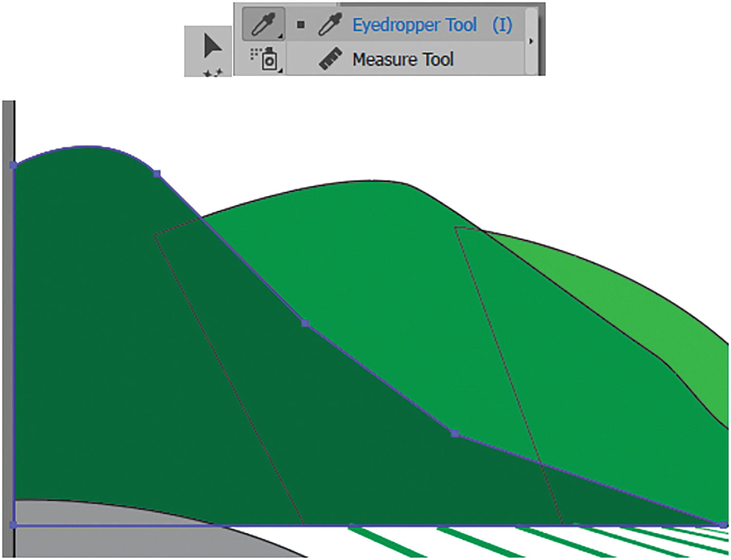
Use the Eyedropper tool to sample colors from the locked layer below
This tool should pick up the attributes from the underlying layer and color the path with those current fill and stroke colors.
Sample colors using the eyedropper tool for the middle mountain and mountain on the right when selected
Next, repeat those steps with the Selection tool on the mountain farthest away on the right with the light green and the foreground area in gray. Refer to Figure 2-198.
If you need to check what current attributes your Eyedropper picks up, you can double-click on it in the Toolbars panel, or when the tool is selected in the Properties panel click on the Tool Options button. Refer to Figure 2-197.
Use the Properties panel to check the Eyedropper tool options
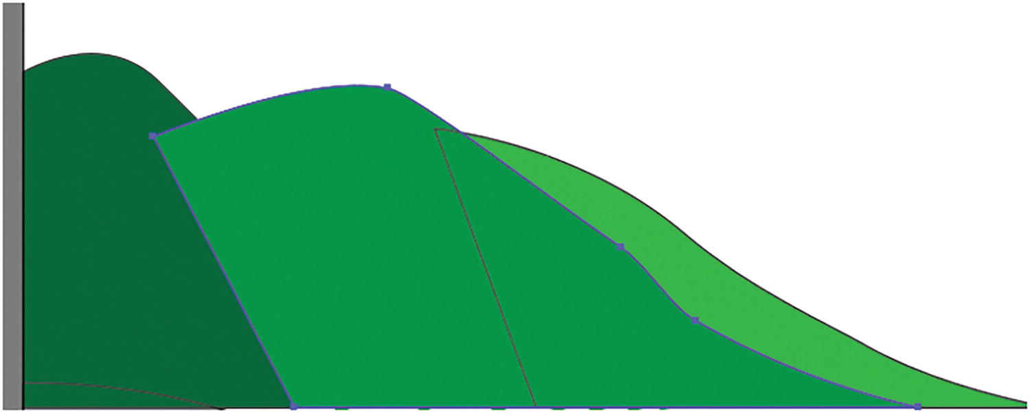
The mountains are currently in the order they were traced, but they need to be behind one another
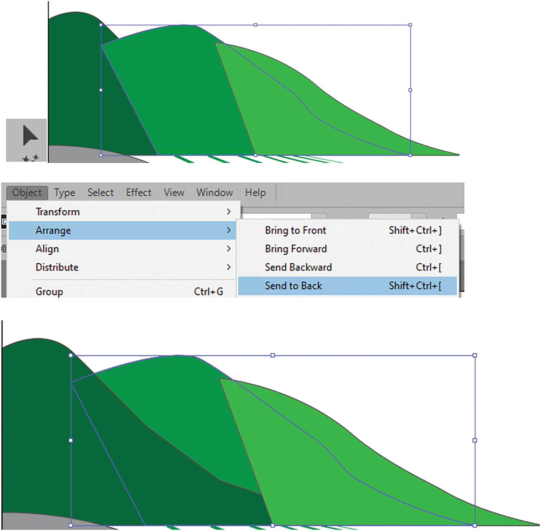
Correct the order for the selected middle mountain using the Object ➤ Arrange menu
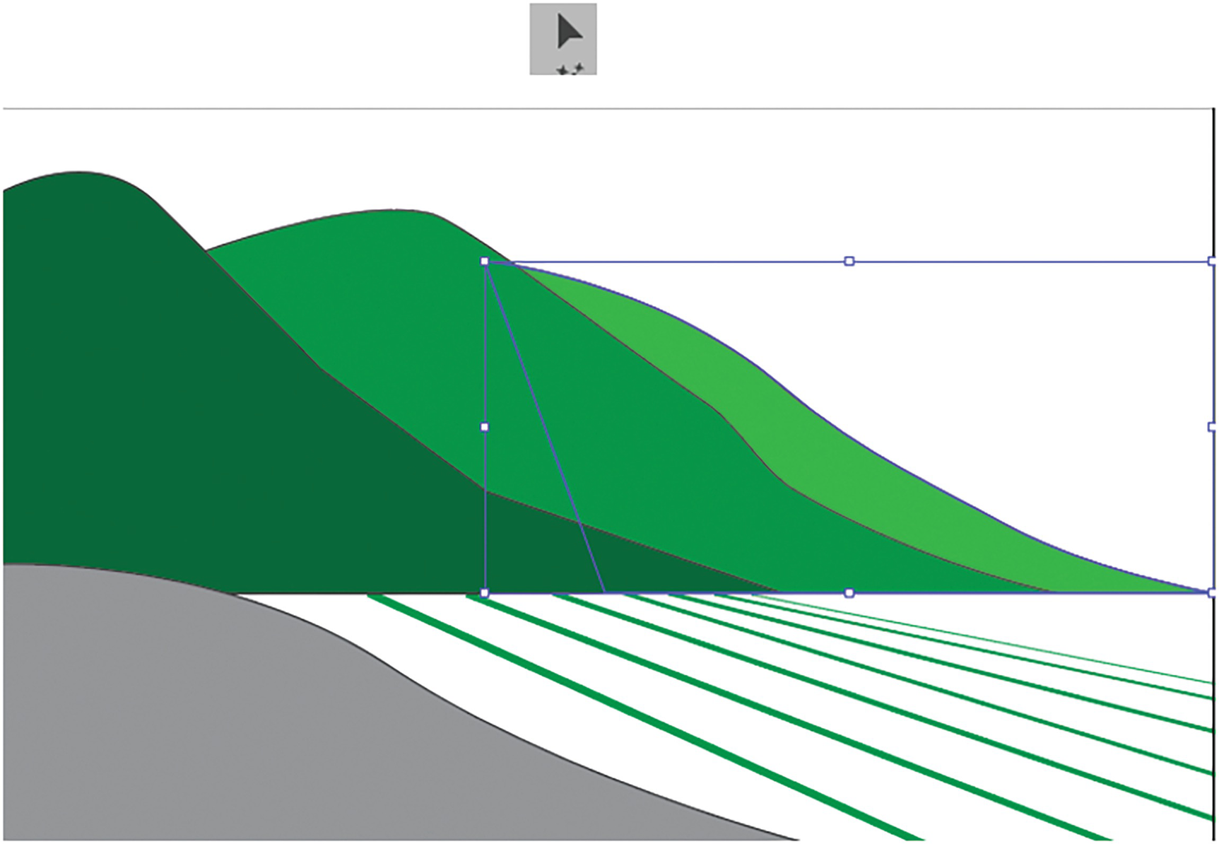
Correct the order for the selected mountain on the right using the Object ➤ Arrange menu
The gray foreground in this case is fine where it is, but if it were below a layer then you could use Object ➤ Arrange ➤ Bring to Front to make sure it was the topmost shape, as we will do a few times later in the project.
Click outside the Artboard if you need to deselect your paths and Ctrl/CMD+- or Ctrl/CMD+0 if you need to zoom out to see the picture.
Using the Line Segment Tool
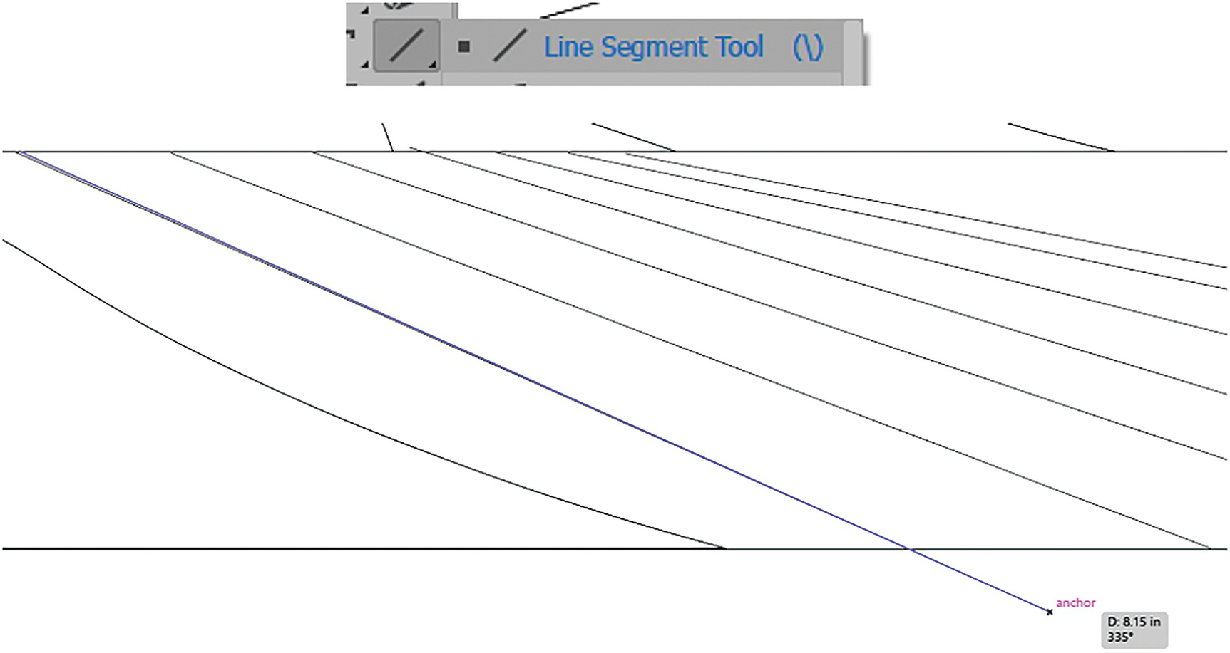
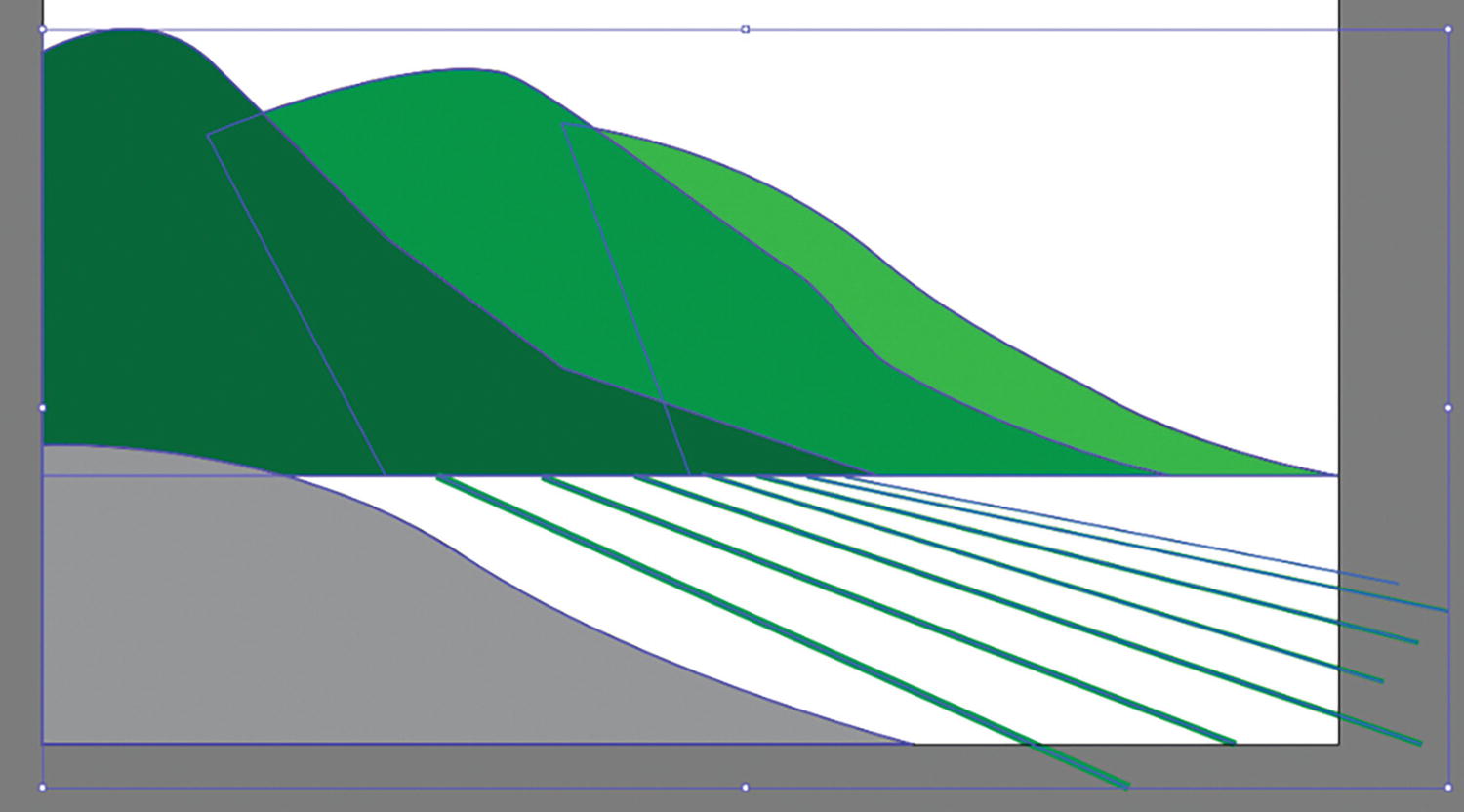
Use the Line Segment tool to create the lines in the field
With your Smart Guides active, you should easily be able to trace over the lines.
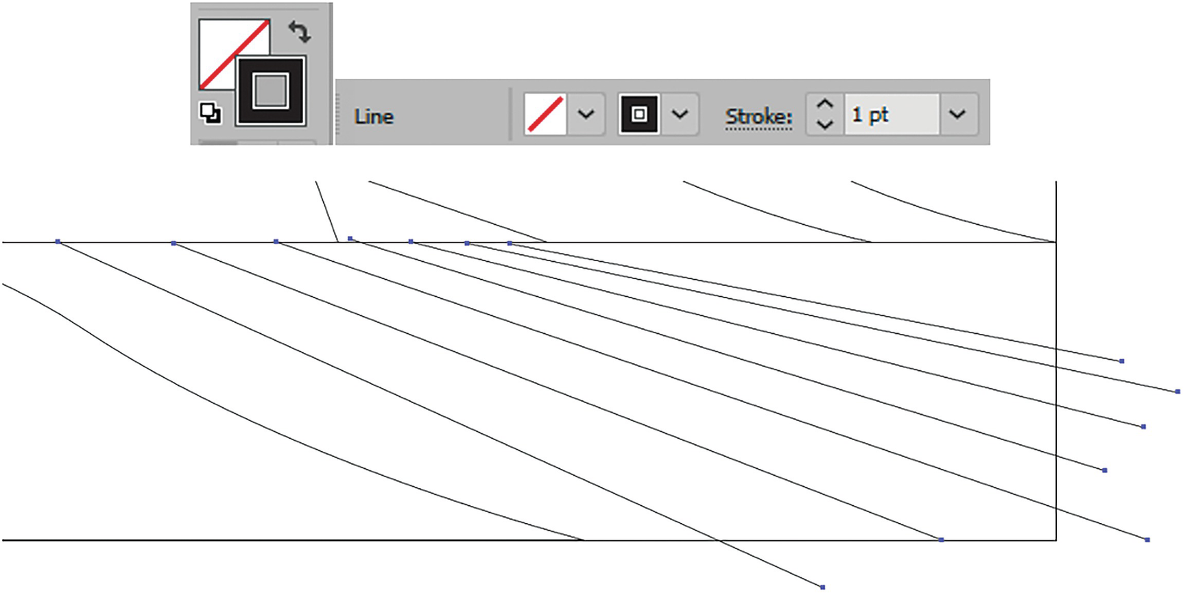
Shift + Click the lines and use the Control panel to set them to black and a stroke weight of 1 pt
Now, return to View ➤ Preview (Ctrl/CMD+Y).
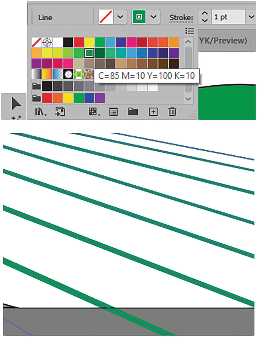
Shift+ Click the lines and use the Control panel to set them to a new color
Click off the Artboard to deselect the lines.

Select each line and set to a new Stroke Weight
Line 2 to 5 pt
Line 3 to 4 pt
Line 4 to 3 pt
Line 5 to 3 pt
Line 6 to 2 pt
Line 7 leave at 1 pt
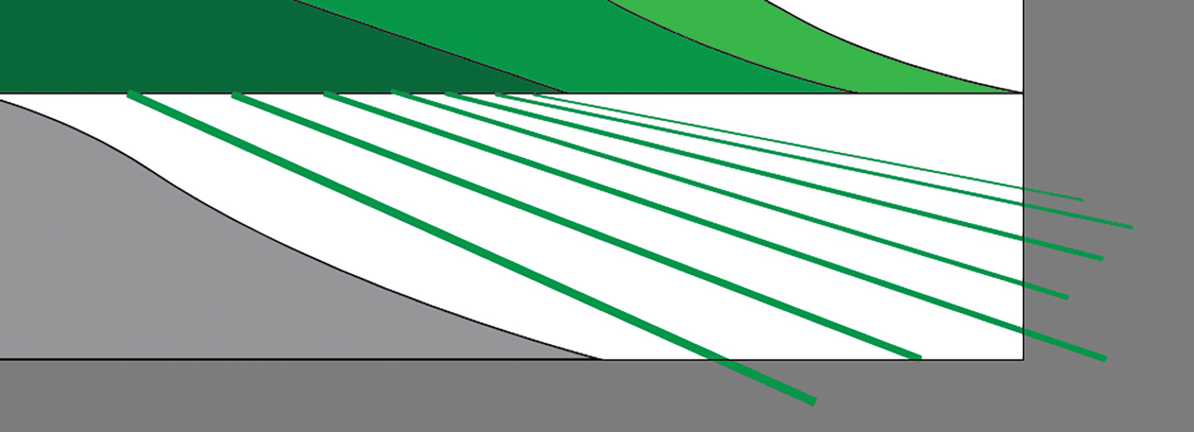
The seven lines with their new stroke weights
This makes the lines look finer as they move into the distance.
Save your work at this point.
Copying and Pasting Between Documents
Layers panel with Layer 3 selected
Select all the paths
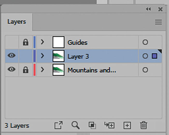
Layers panel with all the paths selected
Now, in the Main menu, go to Edit ➤ Copy (Ctrl/CMD+C) and return to your copy of the Landscape1_start.ai document.
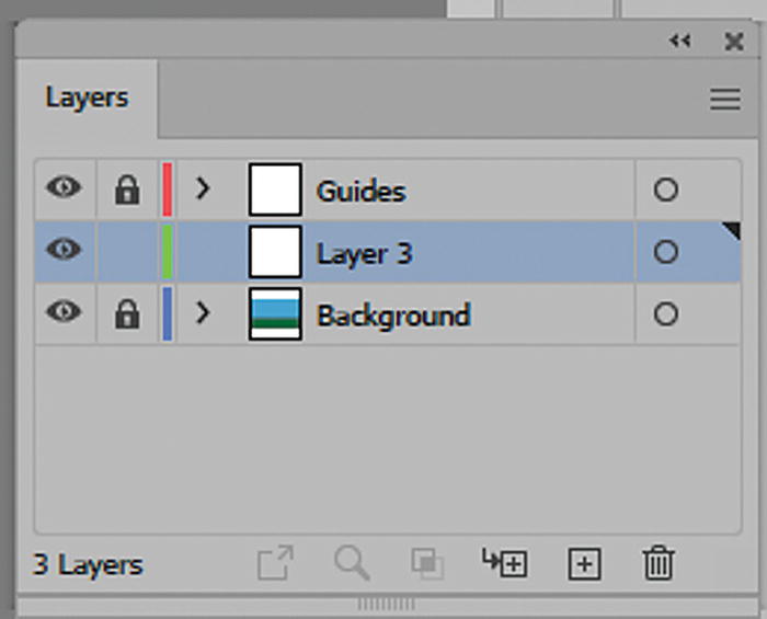
Back in the Landscape1_start document with Layer 3 selected
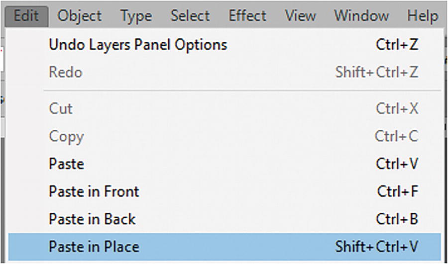
Use the Edit menu to paste the paths in place

The paths pasted into Layer 3
Rename Layer 3 in the Layers panel

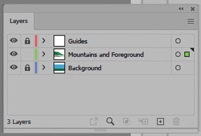
Lock the Mountains and Foreground layer, create a new Layer 4, and use the Ellipse tool dialog box
Using Ellipse Tool to Create a Sun
Now create a new layer in the Layers panel, Layer 4, above the Mountains and Foreground layer and select the Ellipse tool. Click on the Artboard to enter the Ellipse dialog box. Set the width to 2.2738 in and height to 1.8876 in. Click OK. Refer to Figure 2-213.
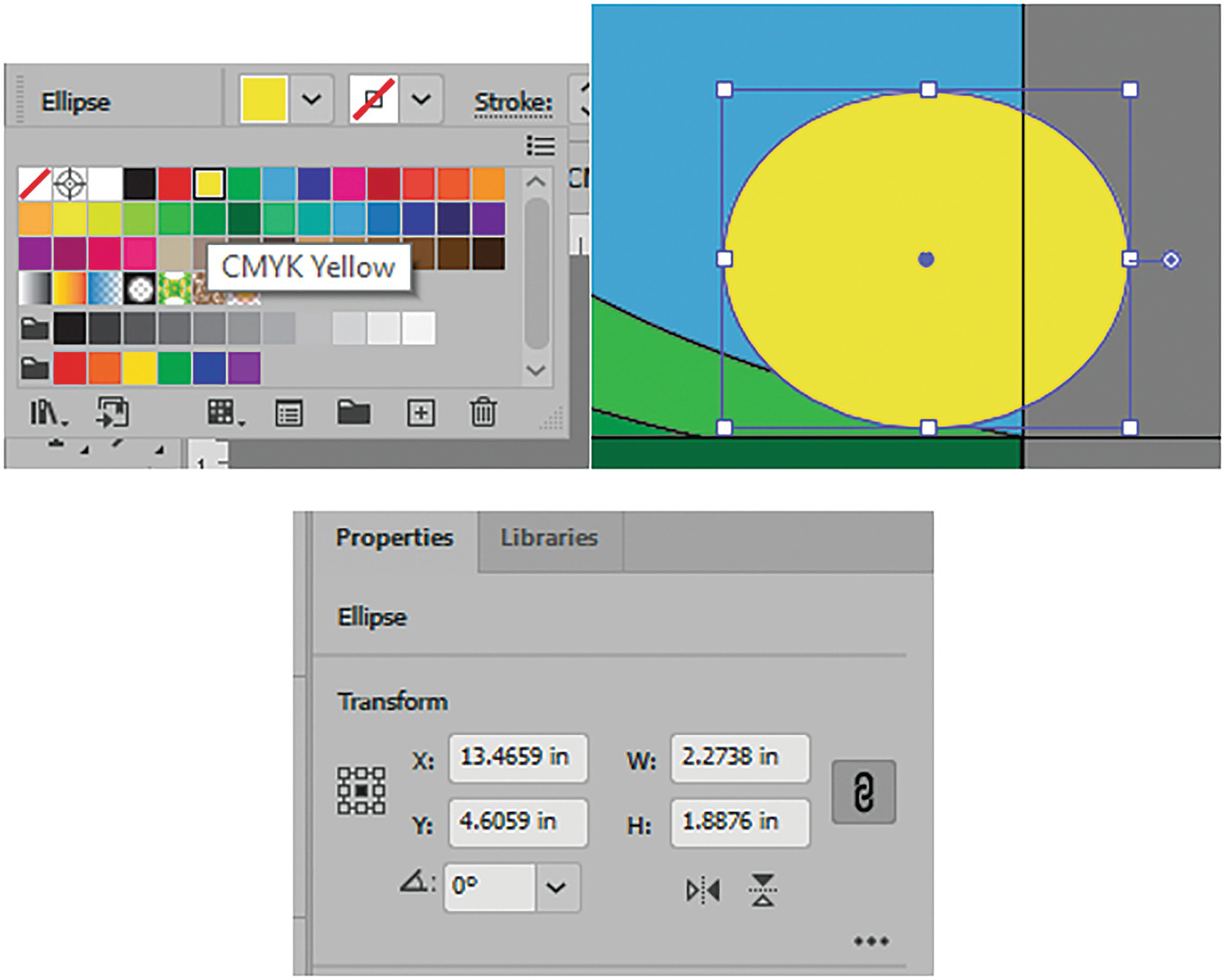
Use the Control panel to set the color of the ellipse and the Properties panel to move it into place
This is not a perfectly round sun as it is low on the horizon and would be more elliptical due to atmospheric distortion. Later in Chapter 8 we will add a gradient so that it appears more sun-like.
Another tool that you can use to create a sun would be the star tool with multiple points. Refer to Figure 2-215.

Toolbars Star tool
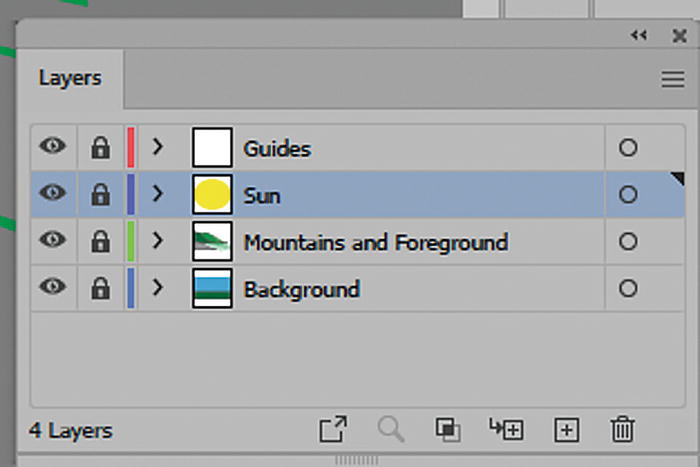
Rename Layer 4 to “Sun” and lock the layer
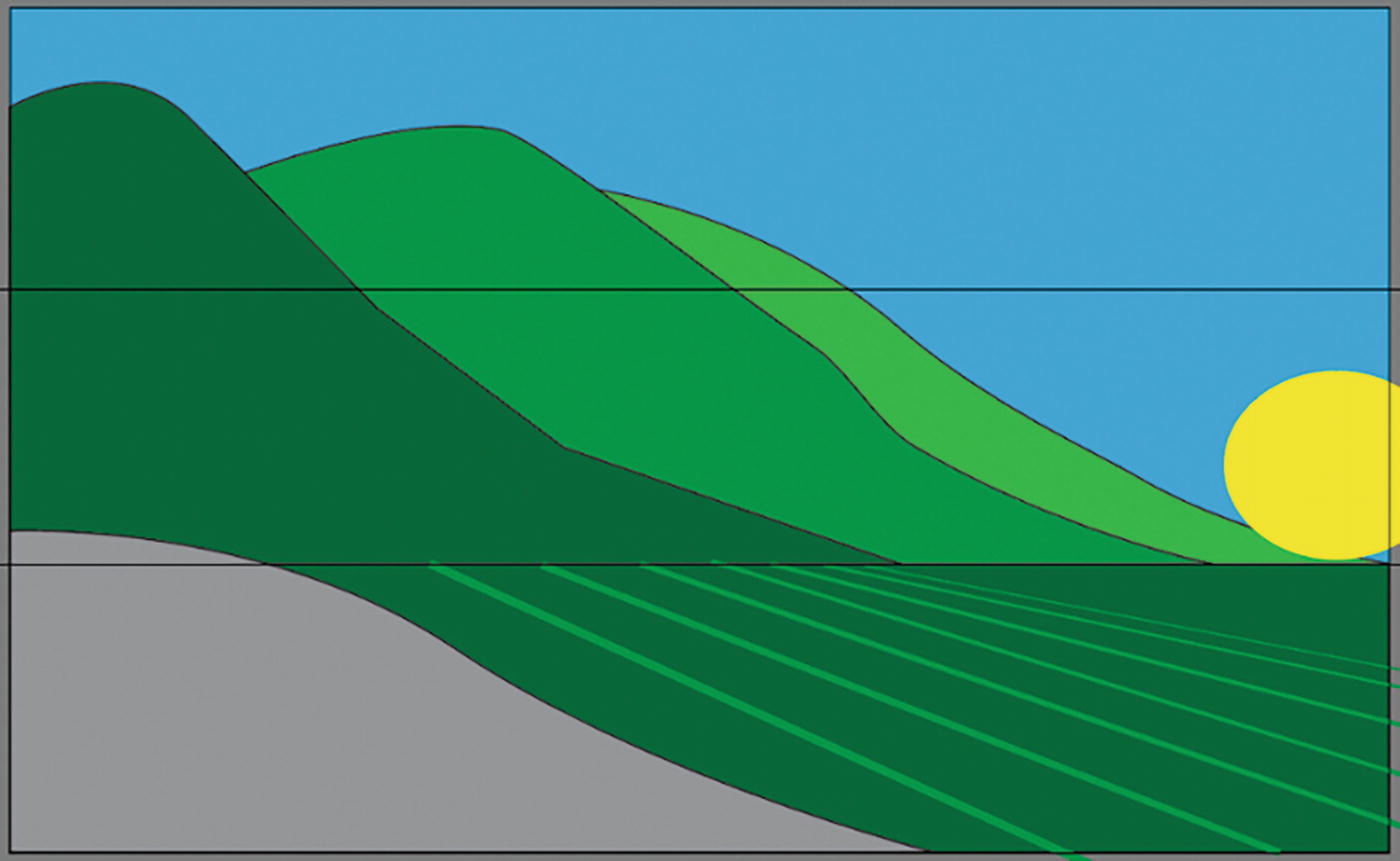
How the landscape currently appears
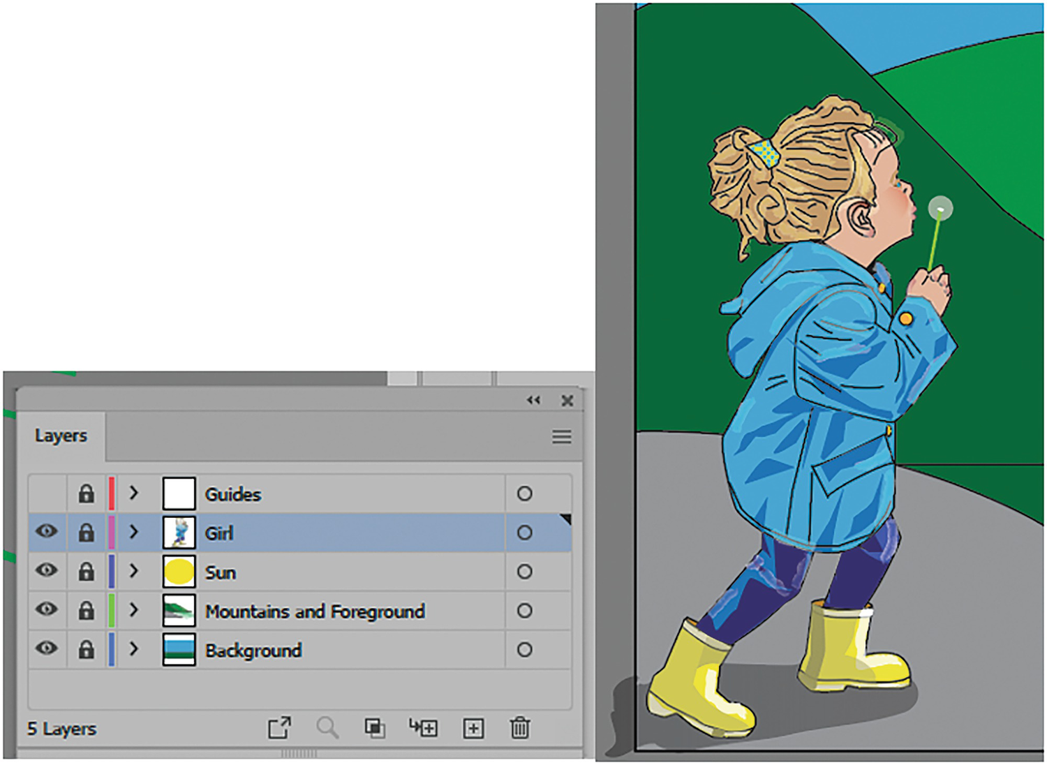
Copying, Pasting, and Placing Grouped Paths
Now, I will copy some group paths of the girl that I created earlier and place that on its own layer to finish this part of the chapter.
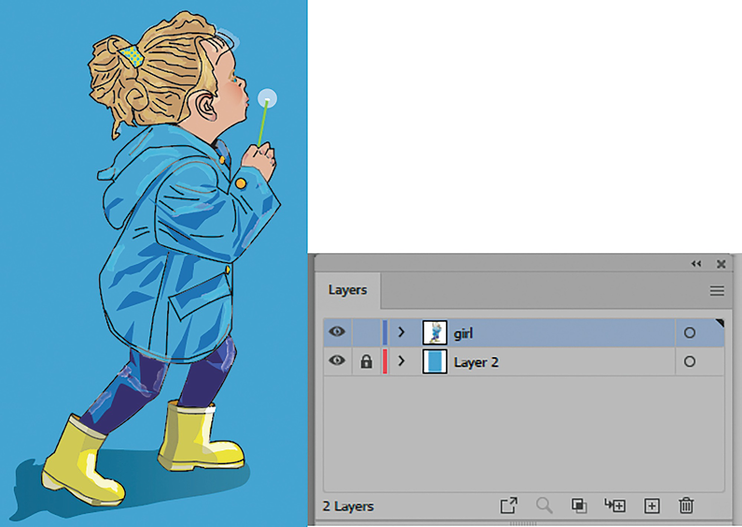
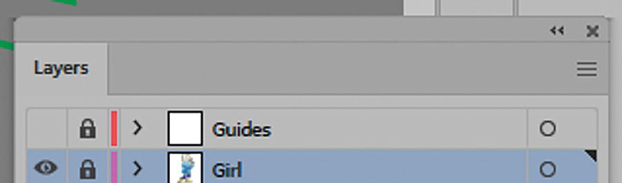
The girl and her placement in the document in the Layers panel
As we progress through the book, I will go into more detail as to how shading, paths, and gradients were used to create this girl. But essentially, she started off as several photos that I placed on a locked layer. I traced over them in Illustrator with the Pen, Ellipse, and Line Segment tools and then used the Selection and Direct Selection tools to modify the points on the path while looking at the underlying photo. This was very similar to what we did with the mountains while using a template layer or a locked layer.
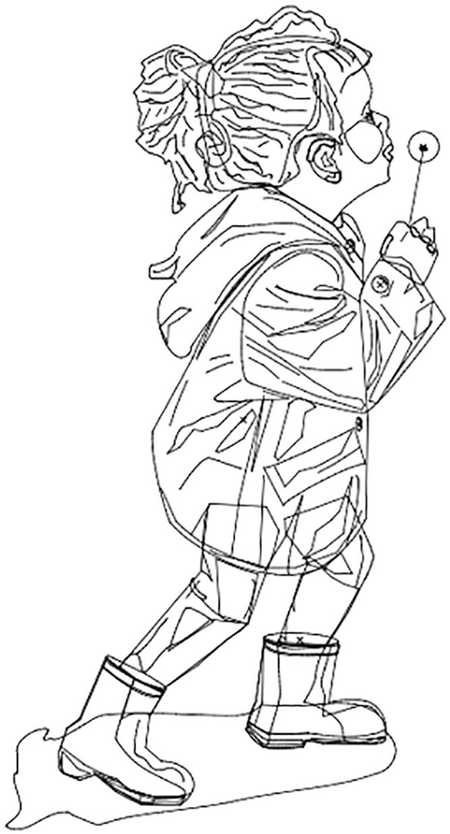
The girl in Outline mode
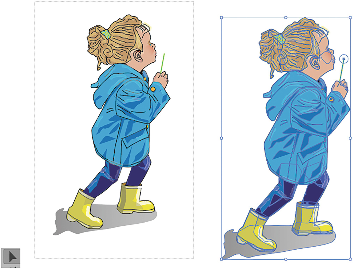
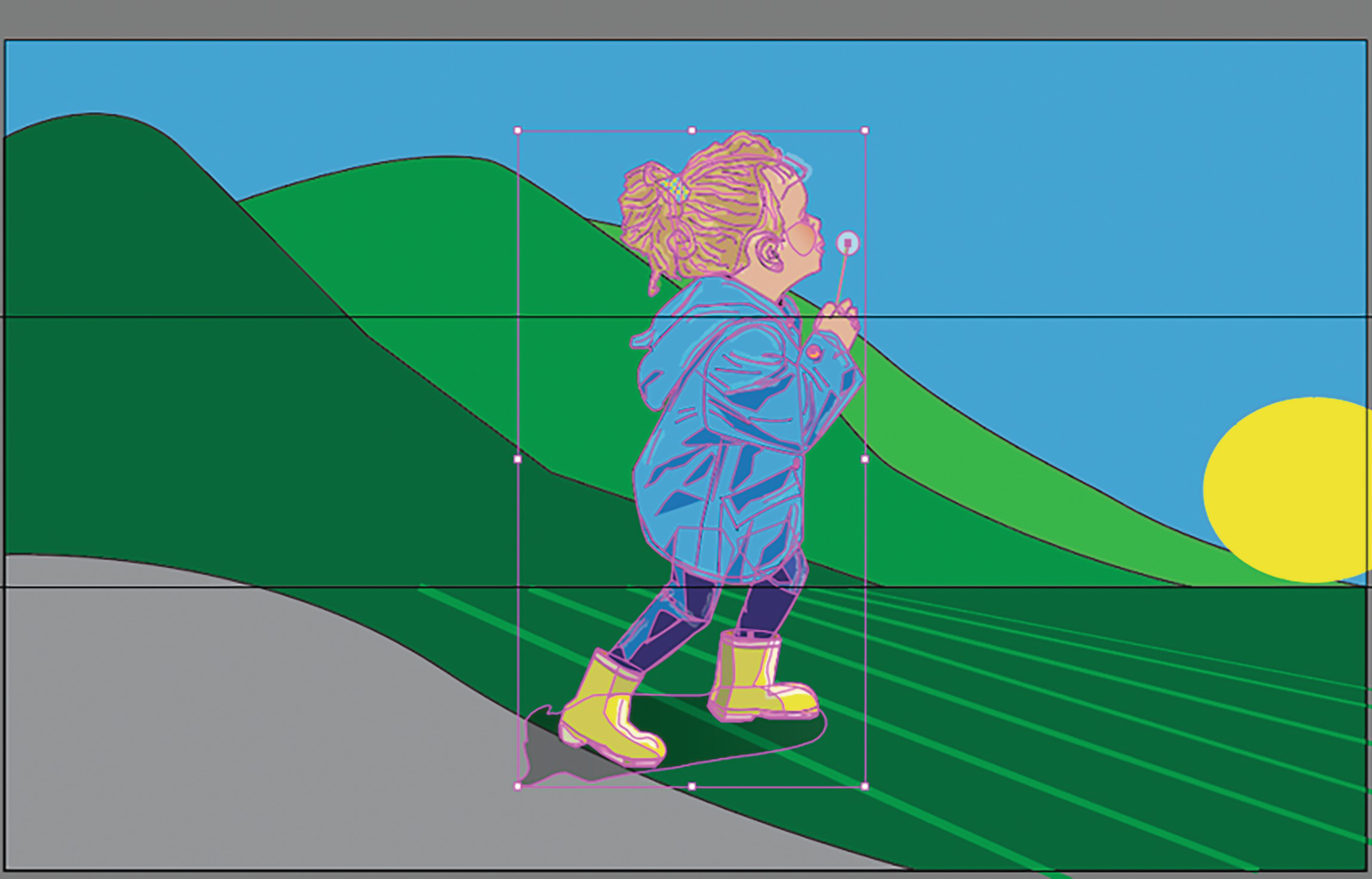
Select the girl with the Selection tool and group the paths
Then, from the menu I choose Object ➤ Group (Ctrl/CMD+G).
This keeps all the paths together so that I can move them as one unit. Refer to Figure 2-220.
While selected, you can go to Edit ➤ Copy (Ctrl/CMD+C).
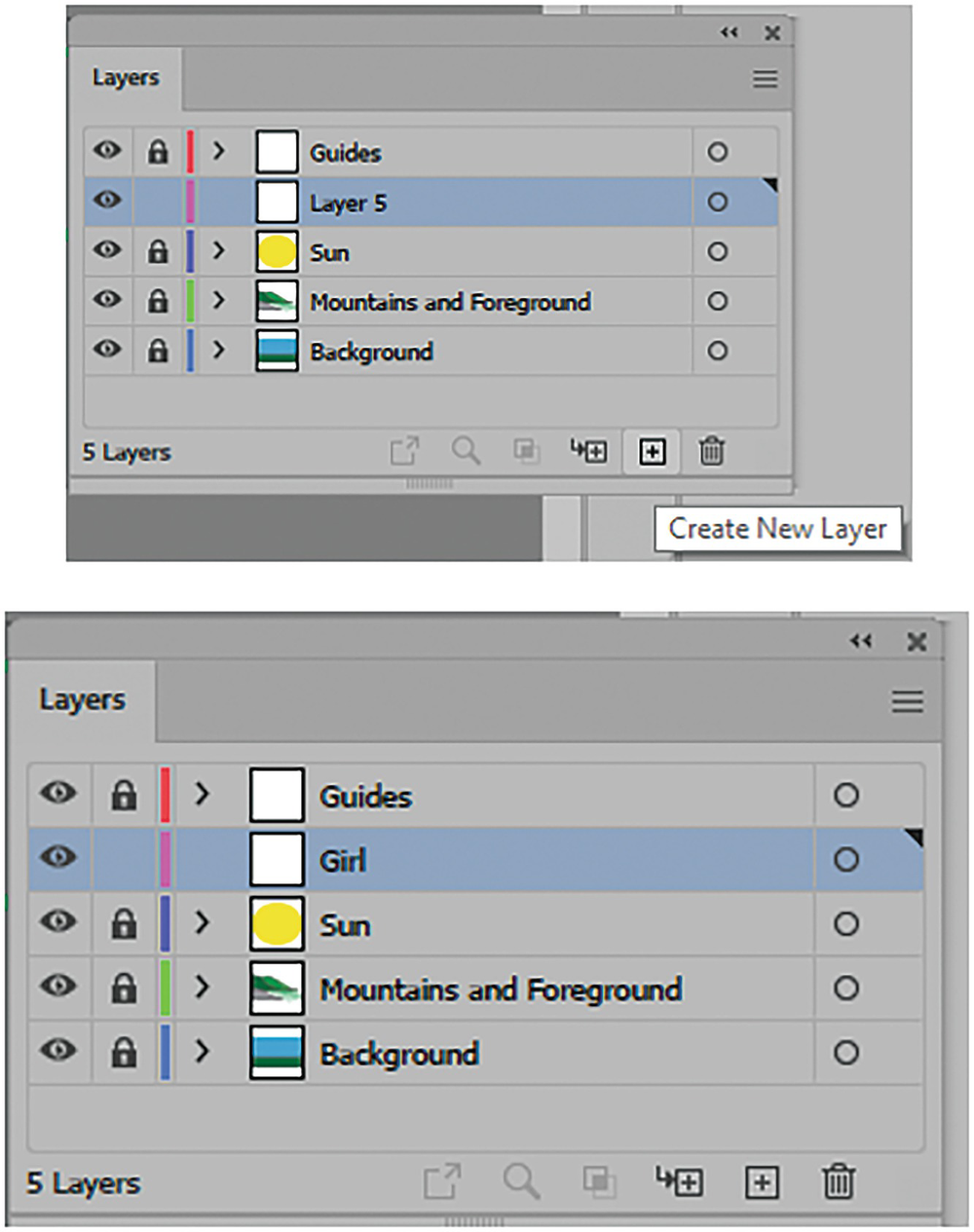
Create a new Layer 5 and rename the layer “Girl” in the Landscape1_start document
Paste the girl into the document
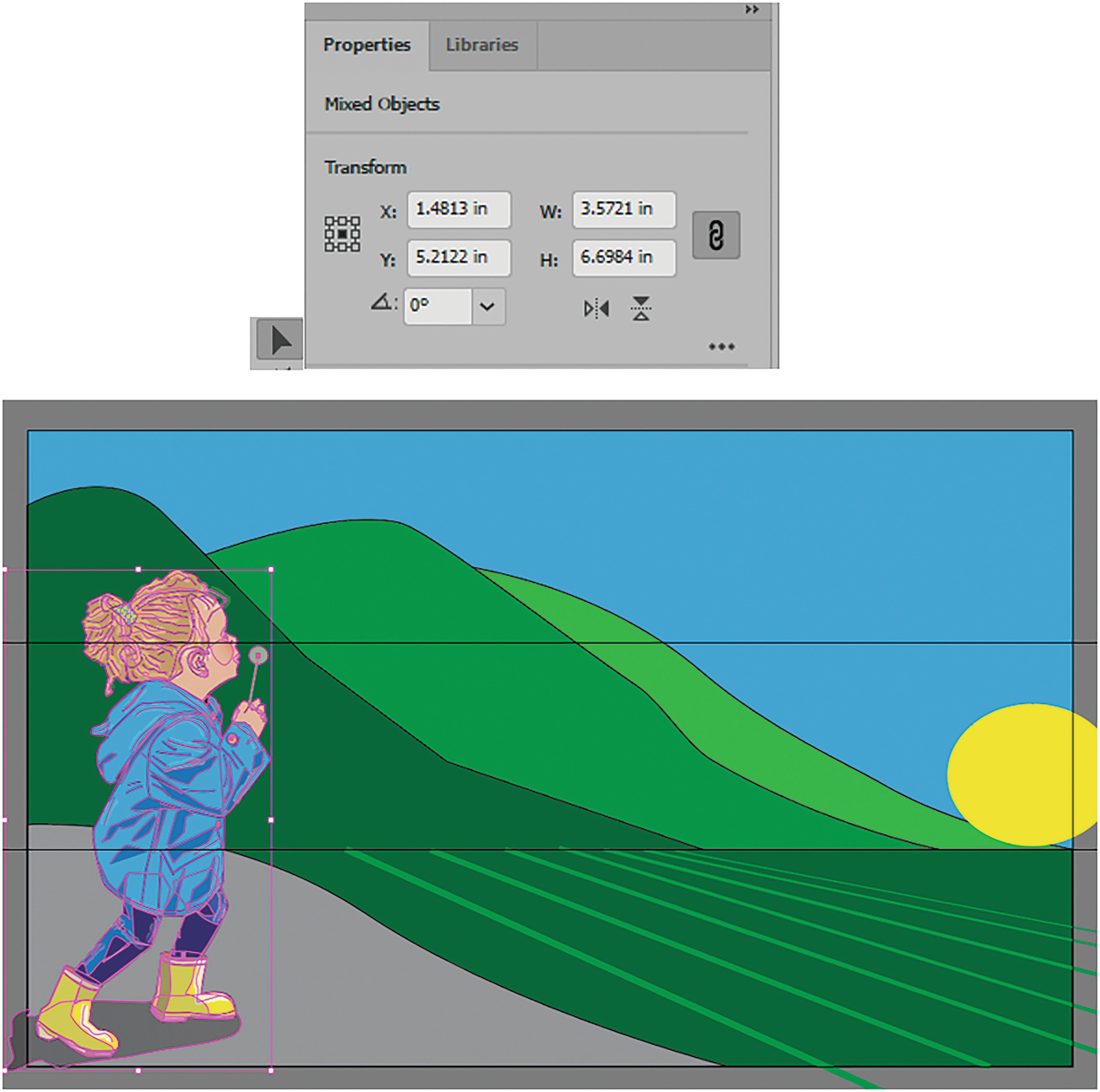
Use the Selection tool and the Properties panel to set the girl at the correct X and Y coordinates
Add Another Line to the Field
Lastly, I return to the Mountains and Foreground layer, unlock it, and drag out one more line with the Line Segment tool. I scale it in the Properties panel to X: 5.1594 Y:6.6971, W: 3.639 in, H: 2.1942 in and set the angle to 328.38°.
In the Control panel the stroke color is set to C=85, M=10, Y=100, K=10, and the stroke weight to 8 pt.
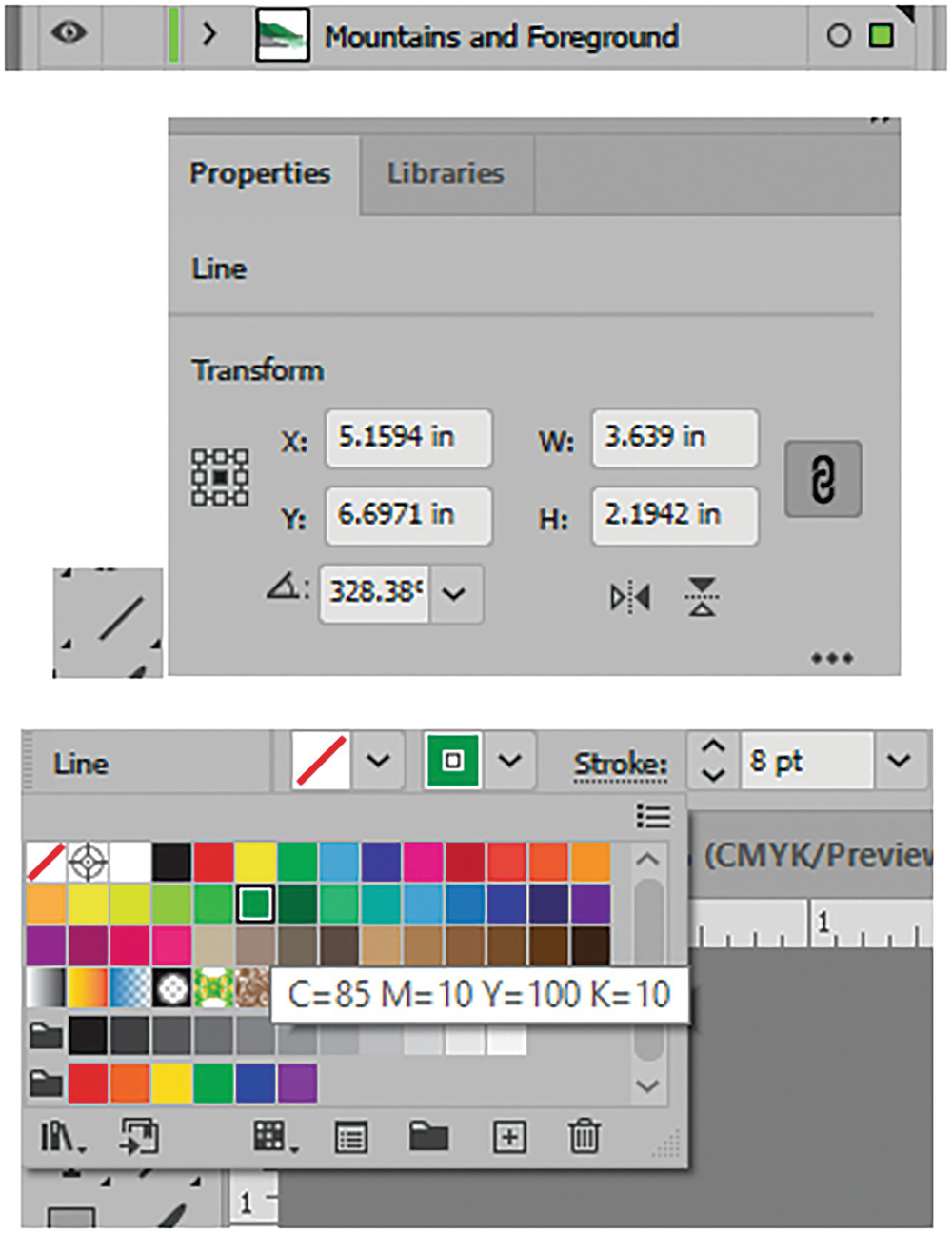
Unlock the layer and draw with the Line Segment tool, set the stroke color, and use the Properties panel to set the X, Y, W, H, and angle rotation of the line
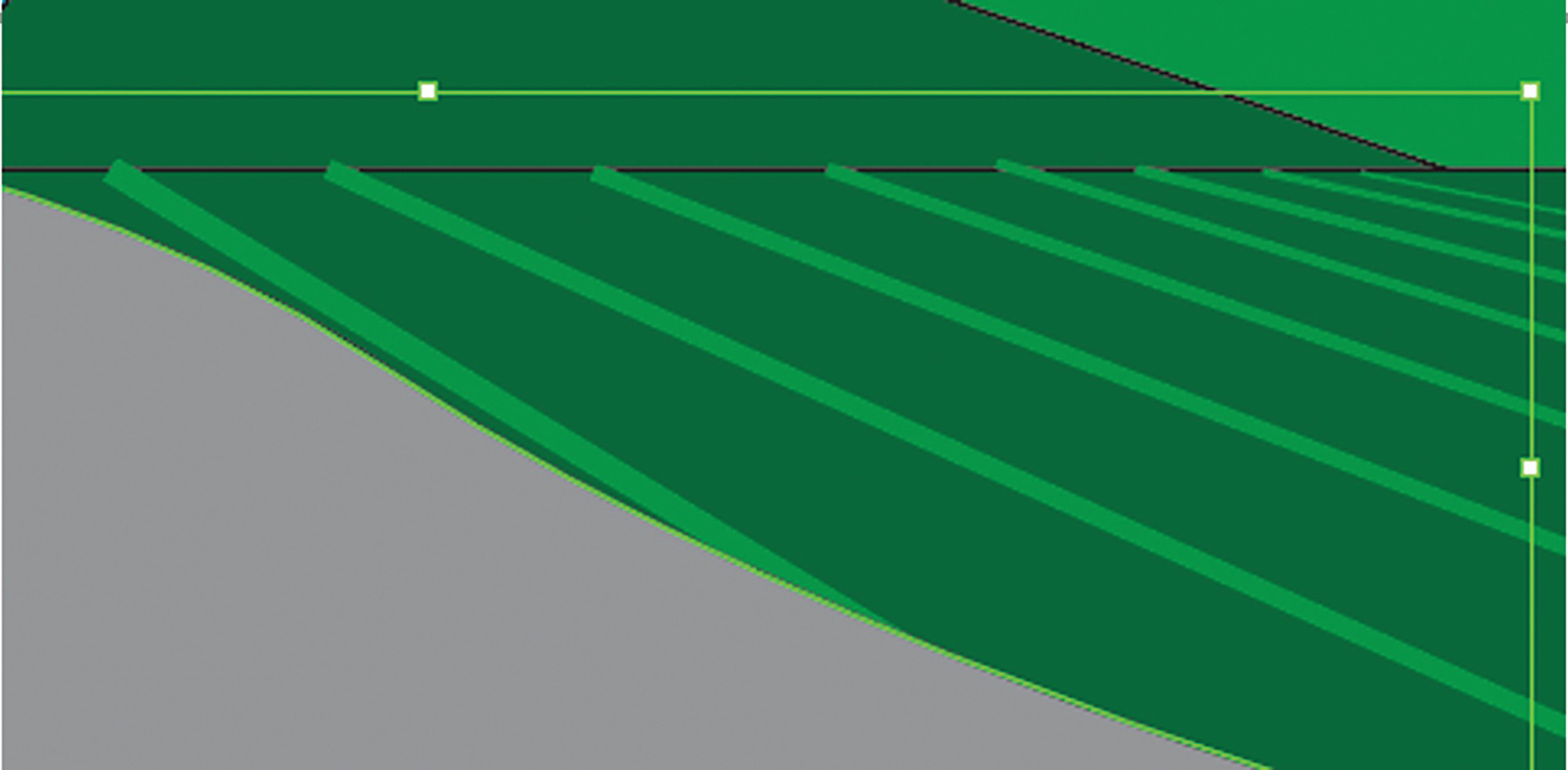
Select the gray foreground and use the Object ➤ Arrange menu to move it above the new stroke
Lock all the layers in your Layers panel
Save your copy of the Landscape1_start.ai file with your initials and close any other open files at this point. You can see my final file Landscape1_1.ai to compare.
Summary
After working with these Pen and Shape tools we can see how basic distorts can be made to each shape or path using the Selection, Direct Selection, and Group Selection tools. You can also scale, rotate, and edit shapes or paths using the Control, Properties, Transform, Align, and Pathfinder panels. Then we saw how paths and shapes can be used to create the start of a landscape image. In the next chapter, we will work with a few more tools to modify distortions as we would with Free Transform tools in Photoshop.