
Solutions in this chapter:
From this chapter on, we will explore several example projects that could be the inspiration for many others of your own creation. As we already explained, the spirit of the book is not to provide you with step-by-step instructions, but rather to give you a foundation of information and let your imagination and creativity do the rest. For this reason, you will find some images of each model, some text that describes their distinguishing characteristics, and tricks that could be useful for other projects. Of course, we don’t expect each detail to be visible in the pictures. It isn’t important that your models look exactly like ours!
Another point we want to bring to your attention is that there is no reason to read Chapters 14-ch25 in order. Feel free to jump to the project that attracts you most, because they aren’t ordered according to their level of difficulty.
In this chapter, we’ll show you some projects that could be considered “classic,” because almost everybody with an NXT kit tries them sooner or later. Though you might not find them exciting, working with them is a good way to build up some solid experience and learn tricks that will prove useful in more complex projects. If this is among your first forays into robotics, we strongly suggest you dedicate some time to them.
All the robots appearing in this chapter have been built primarily from the NXT kit. When describing some of the robots, a few extra parts may be necessary that do not exist in the NXT kit. However, most of these are pretty common and you can find them if you have other TECHNIC sets.
Well, actually exploring your room is too strong a term for what we are proposing here; it’s more like surviving your room—your robot and your furniture could take some hits! The task here is to build a robot with the basic capability to move around, detect obstacles, and change its route accordingly.
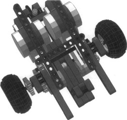
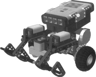
For simplicity of design, and for the robot’s capability to turn in place, we suggest you make this robot from differential drive architecture, such as the one shown in Figure 14.1.
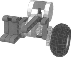
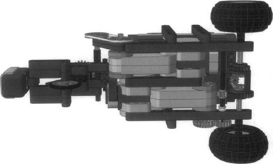
We deliberately chose a gear ratio that makes the robot rather slow: 1:9, obtained from two 1:3 stages (Figure 14.2). This ensures that if you make some error in the code and the robot fails to properly detect the obstacle, it won’t collide with it at too high a speed. Never expect everything to go well on the first try—because it won’t!
When you feel satisfied with your software and your robot runs safely around your room, you can always try a faster ratio. Substituting the second 1:3 gearing with two 16t gears will give you an overall 1:3 ratio, making your robot about three times faster.
The robot is rather large, keeping the main wheels far from the body of the robot. There’s a reason for this too: In a differential drive, the distance between the drive wheels affects the turning speed of the robot, because the wheels have to cover a longer distance during turns. The farther the wheels are from the midpoint, the slower the turns. You could control turns through timing, which would make slow turns a desirable property that would provide finer movement control. However, with the NXT’s built-in rotation sensors, navigation via rotations provides more consistent control of the turns.
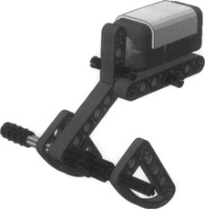
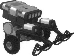
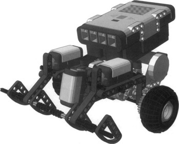
The caster wheel is the same kind we showed in Chapter 9. Now add the NXT and a couple of bumpers that are normally closed (see Figure 14.3), and you’re ready to go—well, ready to program the robot, anyway. Check out Figure 14.4 to see what the completed robot looks like.
The program itself is very simple: Go straight until one of the touch sensors opens. When that happens, reverse for a few fractions of a second (or rotations), then turn in place, right or left depending on which bumper found the obstacle. Finally, resume straight motion.
Experiment with different timing/rotations for turns, until you are happy with the result. You might also use some random values for turns to make the behavior of your robot a bit less predictable and thus more interesting. If you feel at ease with the programming, you can add more intelligence to your creature—for example, to make it capable of realizing when it’s stuck in a cul-de-sac. You can achieve this by monitoring the number of collisions in a given time, or the average time elapsed between the last n collisions, and then adopting a more radical behavior (such as turning 180 degrees).
If your room has a flight of stairs going down, simply equipping the robot with an ultrasonic sensor facing the floor to sense the edge can avoid a bad fall. However, if you want to use your ultrasonic sensor for some other purpose, you could use a touch sensor instead, connecting the touch sensor to a feeler flush with the ground. When the feeler in front of the robot drops, you have detected an edge.
Unless you have a third touch sensor, you are forced to use the light sensor. It’s time to look back at some of the tricks explained in Chapter 4 and see whether you find something useful. A light sensor can actually emulate a touch sensor: You have to place movable parts of different colors in front of it so that when contact is made, the parts move, and the color of the brick in front of the light sensor changes.
However, as your kit contains the ultrasonic sensor, use it, because this sensor is ideal for this purpose. We kept the ultrasonic sensor behind the bumpers so that in most cases it doesn’t interfere in obstacle detection (Figure 14.5).
Unfortunately, this system doesn’t cover all possible scenarios, because your robot could approach the edge at an angle that allows a wheel over the edge before detection occurs. You can improve upon the design and avoid this by providing the robot with two left- and right-edge sensors, but you’ll probably have to give up the double bumper and go with a single sensor bumper.
Using a different approach, you could write the software to make the robot very cautious, turning slightly left and right from time to time to see whether there’s a dangerous precipice around.
By using the NXT motor’s built-in rotation sensor, you can experiment with indirect obstacle detection. Program the robot to monitor the rotation count while in motion. If both motors are on forward, but the count doesn’t increase, the robot knows an obstacle has blocked it. As a positive side effect, the rotation count allows you to use the same platform for experimenting with navigation, applying some of the concepts about dead reckoning explained in Chapter 13.
You can also implement indirect obstacle detection using a “drag sensor.” The idea requires that your robot keep a mobile part in touch with the ground, and that the friction this part exerts against the floor surface when the robot moves activates a touch sensor. For example, you can use the friction of a rubber tire to oppose the force of a rubber band that keeps a touch sensor closed. When the robot moves, the friction of the tire on the floor overcomes the force of the rubber band and opens the touch sensor; as soon as the robot stops—or has been blocked by an obstacle—the friction disappears and the touch sensor closes.
The line-following theme is often mentioned in this book, as we think it is a very useful indicator of how different techniques can improve the behavior of a robot. The time has come to give it an official place, and face the topic in its entirety.
Let’s review what we have already said about line following:
You must actually follow the edge between the tape and the floor, reading an average value between dark and bright, so that when you read too dark or too bright you know which direction to turn to find the route back.
If you want to keep your software and robot as general as possible, you should use some kind of self-calibration process before the actual following begins. Calibration consists of taking readings of light and dark areas on the pad before actually starting line following. This lets your robot adjust its parameters to the actual lighting conditions at the time it runs; these conditions are almost certainly different from those for which your robot was designed.
Some platforms can benefit from the introduction of a small quantity of hysteresis to reduce the number of corrections and get a higher efficiency. We explained in Chapter 12 that hysteresis “widens” the gray area between light and dark, which keeps the robot from spending too much time on course correction instead of moving forward!
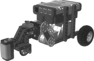
To turn theory into practice and experiment with line following, you can use the same differential drive as in the previous project in this chapter. Remove the bumpers and mount a light sensor facing down, as shown in Figure 14.6.
You can easily swap the ultrasonic sensor for a light sensor, which is attached to the structure with a long pin. Observing the result, the light sensor is now fairly far from the floor. The distance of the sensor from the pad is very important. Therefore, you should lower the attach point for the light sensor so that the sensor is much closer. Our experience teaches us that for the best results, this distance should fall in the range of 5 mm to 10 mm.
Now that you’ve finished, you’re ready to program and test your robot for line following. If you want to, you can use the RobotC sample code from Chapter 7, or you can use some of the references in Appendix A. It shouldn’t be difficult to adapt it to the language of your choice.
Suppose you have succeeded in the task of programming for line following, and you feel quite happy with the result. You have good reason to, but you should also wonder, as always, whether you can do anything else to make it better. What could “better” mean in this case? Probably “faster,” along with little to no errors. This is what standard line-following competitions are about: going from one end of a line to the other in the shortest time, and at the highest speed.
Observe carefully your differential drive in action. When it turns in place to adjust the course, it makes no progress along the line. This approach gives your robot the capability to follow a winding line closely with very tight turns, but it isn’t very efficient. A first step could involve changing the course adjustment algorithm to a better one—for example, making the robot turn with one wheel stopped and the other in motion, instead of turning with one going forward and the other reversed. Try this technique, and you’ll see that your robot progresses much faster.
We haven’t yet mentioned the most obvious improvement—increasing the speed of your robot! Try different gearings until you find the fastest setup that still allows your software to keep the course.
Nothing more you can think of? Imagine yourself standing over a line, straddling it with one leg on the left side and the other on the right. Now, gazing at the line, you advance one foot or the other, trying to keep your eyes centered above the line. Do you feel a bit stupid? We would. This isn’t actually what you would do to follow a line in a real situation. You’re not a differential drive. You would rather walk as usual, putting one foot in front of the other, simply changing your direction without changing your speed.
That’s the key: You need something that changes its direction without affecting the speed. Looking back at Chapter 9 with a different eye, you will discover that the steering drive and the synchro drive actually share this property of allowing changes in direction without changing the speed of their driven wheels. The synchro is probably too complex in gearing to be really efficient, so use the traditional steering drive. If you exclude turns with a very short radius from your path, proceed with the steering drive architecture that is simpler to implement.
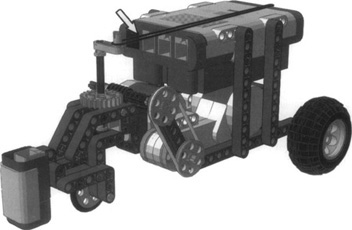
It’s not imperative that a steering drive have four wheels, so ours will actually be a tri-cycle, because this makes the platform easier to build. Figure 14.7 shows our version of a steering line follower.
Let’s dissect it to understand some of the choices we made, starting with the drive gearing; you might think this is a bit more complex than necessary (Figure 14.8).
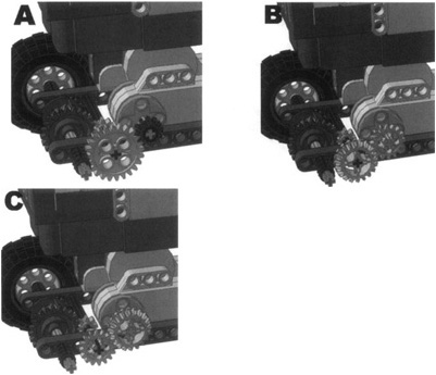
Although it is possible to drive the differential from the motor without so many additional gears, we were looking for an easy way to change the gear ratio without having to take the robot apart. While you build the robot, you don’t know yet at what maximum speed it will be able to keep following the line. Our solution brings a pair of gears on the outside of the model at a distance that allows at least three combinations, so it will be easy to experiment with different speeds (Figure 14.9, versions A, B, and C):
24t 12t (2:1)
20t 16t (5:4)
16t 20t (l:2)
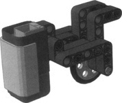
Now turn your attention to the front assembly. It’s very simple, and there are just a few things worth mentioning. There is a TECHNIC pin (3L double) with an axle hole that makes the fork drivable by the steering assembly, and several liftarms that hold the light sensor at some distance in front of the wheel (Figure 14.10).
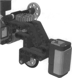
The front fork is driven by a steering assembly based on a worm gear, a 24t and two pulleys. As you learned in Chapter 2, the pulley-belt systems prevent any stall situation if the robot doesn’t control the steering wheel properly when the software is not yet fully tested and debugged (Figure 14.11).
Now it’s time to program and test the robot. If you wrote the line-following program for the differential drive, it will work for this robot with a few minor modifications. During the run, the drive motor will always stay on, while the robot will adjust its course using only the steering motor, in either forward or reverse direction.
As for the calibration procedure, we suggest that with the robot still and placed on the borderline, you make it rotate the front wheel slightly left and right to read the minimum and maximum light values, then compute the average and position the light sensor onto that. This architecture needs very small hysteresis, or none at all.
Start at slow speed, mounting a 12t gear onto the motor shaft, and when your robot is able to follow the line properly, try to change the ratio and increase the speed.
The minimum radius that the robot can follow depends on a combination of the forward speed of the robot, how quickly the turn drive motor can move the steering wheel, and how far in front of the robot the light sensor is. We encourage you to experiment with these variables and see how the robot behaves when following lines with turns of different radii.
You should be happy with this line follower. It runs very smoothly compared to the differential drive configuration. Nevertheless, you might wonder whether you can do anything to make it run at an even higher speed.
Changing the gear ratio is not enough. There is a large margin for an increase in speed—it’s not difficult to set up a LEGO NXT robot to run at about 2 m/s (6.5 ft/s). The problem is keeping the robot on the line.
When you are targeting excellence, the finer details are vital. There is a big difference between building a robot that “works” and a robot that is optimized for a given task. You already switched from a differential drive to a steering drive, and this change of architecture has proven to be a significant improvement, but now you have to dig into the particulars if you want to gain some additional speed. In working with line following, one of the key factors is to make the steering fast and accurate. To achieve this, you can reduce the backlash between the 24t and the worm gear, for example, keeping the steering gently pulled back from one side with a rubber band. Use a long and soft rubber band, because you don’t want to introduce too much friction; you want to simply keep the teeth of the 24t in contact with the worm gear, and always from the same side (Figure 14.12).
At this point, speed limitations are probably due to the rotation speed of the steering assembly. This pulley, belt, and worm gear system is safe and accurate, but a bit slow. We leave you the task of developing a faster steering assembly. It’s not very difficult: Try to connect different pulley sizes to the steering mechanism...
Now you will meet the last barrier: the reaction time of the software. If you used the standard firmware, either with NXT-G, RobotC, or other tools, the time it needs to interpret the instructions becomes relevant to the performance of your robot. Another very critical factor is the sampling frequency of the sensors, which is much higher in most replacement firmware than in the original LEGO one.
You may not have any interest in the topics covered in this chapter—you may think “What a bore. I’d like my robots to do more than just follow a black line or run around my room bouncing against obstacles...”
You’re right; there are more interesting activities you can program your robots for, but these classic tasks help lay the foundation for more complex projects in the future. They reveal that even apparently trivial projects conceal unexpected difficulties, and we’re sure the time you spend experimenting with line following and simple navigation will indeed pay off in the end. In this chapter, you also had the opportunity to review many of the tricks learned in this book and see them at work. We applied the concepts of Chapter 6 to make solid structures and build two of the most important types of mobile configurations described in Chapter 9: the differential drive and the steering drive. Naturally, to build these configurations we used the principles of the first two chapters concerning the geometric relationships of LEGO parts and the proper use of gears. We recalled the techniques of Chapter 4 about making good bumpers, about using light sensors for line following, and even about emulating a touch sensor with a light sensor, and we introduced an important application of the ultrasonic sensor. From Chapter 7, we took the idea that good code should be as general as possible, and for this reason we suggested using a self-calibration routine to make your line follower suitable under any light conditions. Even the math of Chapter 12 had its applications here: We recalled the idea that hysteresis can improve the efficiency of your robot in tasks such as line following.
Like a thread sewing together most of the topics that we covered in this book so far, the simple robots of this chapter demonstrated what we’ve stated on more than one occasion: Robotics involves many disciplines, and a good design cannot neglect any of them!
Another theme that pervades the chapter concerns the care you should put into the particulars: Building a robot that works roughly as expected, compared to looking for optimal performance, are two very different approaches. Obviously, the concept behind the design of a robot is an important element in regard to its functioning. But even after finding a satisfactory architecture, there is still much work to be done to optimize the subsystems of the robot. The details, as often happens, make the difference. You will see this prove true in Chapter 20 and 21, where we will explore the world of robotic contests. Contests are a great incentive to pursue optimization, the kind of motivation that makes you spend all night rebuilding a working robot from scratch in search of that little improvement that will make all the difference!