
For this exercise, we will need:
- 4-pin push button
- Male-to-male jumper wires
- Half-size breadboard
- LED
- 470Ω resistor
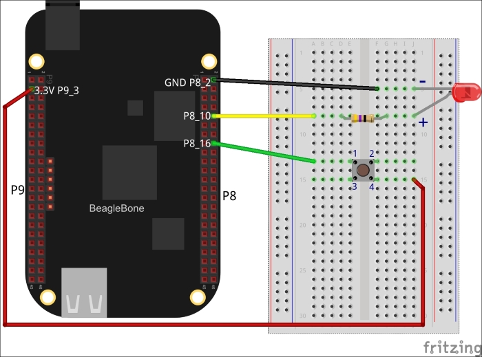
Power off the board and attach components to BeagleBone as shown in the preceding diagram.
This circuit is a combination of a push button circuit and the blinking LED circuit we studied earlier. P9_3, push-button and P8_16 create a push button input circuit. P8_10, LED and P8_1 create LED output circuit. Both circuits are independent. Our program listens to input circuit and responds on the output circuit.
..................Content has been hidden....................
You can't read the all page of ebook, please click here login for view all page.