
For this exercise, we will need:
- 4-pin push button: A push button is an electronic component that is attached to two points in a circuit. It is also called a tact switch. When it is pressed, it joins these two points and the circuit is completed. The circuit is disconnected when the button is not pressed.
- Male-to-male jumper wires: We need jumper wires to connect BeagleBone and components through a breadboard.
- Half-size breadboard: A breadboard is needed to create a solderless circuit.
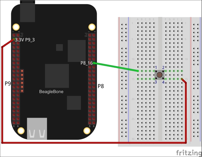
Power off the board and attach the components to BeagleBone as shown in the preceding diagram.
Let's see the analysis step by step:
- The 4-pin push button is divided into two sides. Within the first side, pole
1and pole2are already connected. Another side has pole3and pole4connected. But these both sides are not connected to each other. When the button is pressed, the pole1and pole2side gets connected to the pole 3 and pole4side. - Pin
P9_3andP9_4are not regularGPIOpins but provide continuous 3.3 voltage. They are useful to provide voltage to electronics components. Here, we apply3.3Vto pole4and the current is stuck there until the button is pressed. Once the button is pressed, pole4is connected to pole1. We have joined pole1toP8_16, which is in input mode. The circuit get completed and current starts flowing fromP9_3toP8_16. If we read pinP8_16now, we will get the valueHIGH. - When we release the button, pole
1and pole4are disconnected and the circuit gets broken. Now, if we read pinP8_16from our program, we will get the valueLOW. In our program, we will print whatever value we find.
..................Content has been hidden....................
You can't read the all page of ebook, please click here login for view all page.