
Universal Asynchronous Receiver Transmitter (UART) is a simple and popular way of serial communication. UART is used to convert data bytes on a parallel bus to serial bit stream which can be sent on a communication line. If this bit stream is given to another UART, it can convert back to the original data bytes. UART uses asynchronous communication, which means it follows all the asynchronous bus rules we learned in the previous section. It also uses optional error checking methods. It was actually a serial chip inside a PC motherboard or serial devices inside a modem, serial mouse, and so on. This IC implements a basic serial communications protocol that transmits and receives up to eight data bits at a time. Over time, UART logic has become widely adopted by embedded systems to give a user system log and console access. Even BeagleBone has serial pins near the P9 header to get system log and console access. Many microprocessors/microcontrollers and electronic devices have UART logic integrated for serial communication. UART is a simple and popular way of serial communication. There are well known Wi-Fi, Bluetooth, RFID modules and GSM modems that support UART communication.
UART standard is all about how data is transferred from one place to another. It does not specify physical parameters like logic level, signal timing, transmission medium, and mechanical connectors. There are different physical standards that can be used with UART like RS-232 and RS-485. They often require a logic level convertor chip. These standards guarantee transfer speed based on distance. Using a standard for physical implementation is convention not compulsion. It is possible to do serial communication between two UART devices at the processor's default logic level (3.3V for BeagleBone) without using any level convertor. This is a simple physical implementation of UART without a standard. There is no throughput guarantee. But this communication works fine if the cable is not very long. Many embedded systems including BeagleBone and devices with a UART bus follow this approach.
In UART, data format and transmission speed are configurable. That is why it has the word "universal" in its title. In data format, the user can configure 5–8 bits of data. The optional single bit of parity can be even or odd. The stop bit can be 1 or 2. By default the data format remains 8N1 which means 8 bit data, no parity bit and 1 stop bit. Transmission speed is configured in the unit baud rate. The baud rate is the number of signal state changes per second. Based on the modulation technique, one baud may represent one or more bits. UART is usually configured with the standard baud rate numbers 9600, 19200, 38400, 57600, 115200. Data format and baud rate configuration must match for both transmitter and receiver in order to have successful communication. There are many variants of UART connection. The simplest UART port just uses TX (transmit) and RX (receive) pins. Two-way full duplex communication is possible by connecting the RX pin of the transmitting system/device to the TX pin of the receiving system/device.
UART is one-to-one communication. It also means if you want to connect many UART devices to BeagleBone, you will need the same number of UART ports on BeagleBone. The BeagleBone processor has a maximum of six UART connections possible. The UART0 port is dedicated to give kernel log and console access to the BeagleBone user. There are six male pins located near the P9 header. UART3 has a TX pin but no RX pin. So, it can be used only to send information from BeagleBone to the connected device. UART4 and UART5 share the same pin that HDMI is using. So, if you want to use UART4 or UART5 then you will have to disable HDMI. This is covered in the Appendix C, Pinmux and Device Tree.
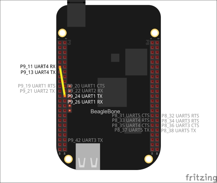
After learning theory about UART, we are ready to write our UART read/write program. Check the above diagram to learn about the UART pins on BeagleBone as well as how to do the connection for our next program. Pins with faded grey text are not enabled by default. Please refer to the Appendix C, Pinmux and Device Tree for information on how to enable them. Usually, UART1 and UART4 are enabled by default. There are some RTS (Request To Send) and CTS (Clear To Send) pins. These pins are helper pins and are optional. As a programmer, there is no need to know much of protocol implementation. Once connected, whatever is written on one UART port is available to read on the UART of the other end. If we connect the TX pin of the UART1 port to the RX pin of UART4 then whatever is written on UART1 is available to read on UART4. We will test write code on the UART1 port and read code on UART4. This is not a two-way full duplex connection. But it is sufficient to cover reading and writing on the UART device we want to test. If we connect P9_13 pin to P9_26 pin, there will be a two-way connection between UART1 and UART4.