
Inter Integrated Circuit (IIC or I²C or I2C) is a serial bus invented by Philips (now NXP). It is popular in the embedded world to interface low speed sensors/devices. It is implemented in more than 1,000 different ICs manufactured by more than 50 different companies. Popular I2C devices include Real Time Clock (RTC), EEPROM ICs, LCD/LED screen display, DAC, ADC, I/O expanders. There are many sensors that support I2C connection like temperature, pressure, humidity, accelerometer, digital compass, and so on. Many I2C bus variants are widely used in consumer electronics, for example System Management Bus (SMBus) is used on computer motherboards for communication with the power source and temperature/voltage/fan sensors. Display Data Channel (DDC) allows the monitor or display to inform the host about its identity and capabilities. I2C specifications are available at this link: http://www.nxp.com/documents/user_manual/UM10204.pdf
I2C bus protocol allows exchange of data through a single data line and clock line. A clock line is called SCL (Serial Clock) and a data line is called SDA (Serial Data). As a clock signal is shared over a clock line, communication is synchronous. Data transfer is bi-directional on single data line. I2C has various modes that work at different speeds from 100 kbits/s to 3.4 Mbits/s. Multiple devices can be connected to single bus. Still, physical interconnection complexity is not there because of only two lines connection. The master device on the bus provides a clock on SCL. It initiates transfer by generating a start and stop condition. It allows a specific slave to talk. It also determines data transfer direction. Every I2C slave device has a 7-bit or 10-bit identification/address. It is usually preconfigured by the manufacturer and listed in the datasheet. Several slaves can be there in the bus. But they should have different IDs. The master uses these IDs to select specific slave device for communication. A I2C bus can have multiple masters. When the stop condition is detected all compete to arbitrate the bus. Whoever succeeds controls data transfer until the next stop condition.
I2C has a major advantage over other buses in that two lines are enough to connect many sensors/devices (there is a need for Vcc and GND connection as well for a device to operate). This reduces the size of the chip, interconnection on PCB and the overall cost of the system. Prototyping is very easy for I2C connection. It has modes that can transfer data faster than UART standard speed numbers. There are some disadvantages as well. Only one device at a time can talk with the master on the bus. It can lead to the starvation of other devices. I2C data transfer is half duplex which is slow when data is getting transferred two ways at the same time. The I2C bus works fine over small distances only. An increase in cable length starts creating a problem. You cannot connect high-speed devices to I2C. I2C is suitable to connect low speed sensors/devices only. Each sensor/device needs to store I2C ID/address. Devices can have address conflicts. Some device manufacturers allow the selection of an address from a small range to overcome this problem.
BeagleBone has three I2C bus channels (I2C0, I2C1, I2C2), of which I2C0 is not populated and used internally to communicate with HDMI, EEPROM, power mgmt chip. I2C1 is disabled by default. Only I2C2 is available for communication by default. I2C hubs can increase the number of free I2C ports. When sensors/devices are connected to I2C pins on BeagleBone, it works as the master. In our next exercise, we are going to connect the ADXL345 accelerometer module via the I2C bus. ADXL345 is a small, low power, high resolution (13 bit) triple-axis accelerometer. It measures gravity acceleration useful in tilt-sensing applications. It is a micro electro-mechanical device that measures change in capacitance of the plates with polysilicon springs. More information can be found at: http://www.analog.com/en/products/mems/mems-accelerometers/adxl345.html.
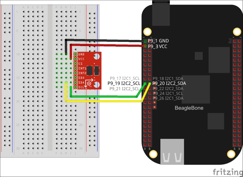
Refer to the following diagram to get information about the I2C pins available on BeagleBone as well as how to connect ADXL345.
Note
Please note that this is a ADXL345 module with pull up resistors that exist on PCB. If it is a simple breakout board without a pull-up resistor, then you will have to add a 5K–10K resistor between the power pin and the SCL and SDL pins. It is recommended that you buy a module rather than breakout board.