PWM can be implemented via program. One can write a program with digitalWrite() and setInterval() to create the desired frequency and desired duty cycle. But context switching and interrupts will make it inaccurate. Also, it will keep the CPU busy. The correct solution is to support this functionality at hardware level inside the CPU. The BeagleBone CPU has a Pulse Width Modulation
Subsystem (PWMSS), which allows the accurate creation of a PWM pattern without keeping the CPU busy. The CPU will be free to do other work while the PWM subsystem takes care of the PWM wave generation. This subsystem has control over only a few GPIO pins. It can switch output very fast on these pins and can control on/off timing. So, not all GPIO pins are capable of generating PWM.
PWMSS has a set of Time Base Counter (TBCNT) register and Output Compare Register (OCR) to generate the desired PWM pattern. OCRs are used to set the duty cycle. You can get detailed information about PWMSS in BeagleBone inside AM335X Technical Reference Manual (TRM). BeagleBone has a total of eight PWM channels. These channels are driven by two types of PWM:
- Enhanced High Resolution PWM (eHRPWM): There are three modules with two channels each. It has three PWM timer registers controlling six PWM channels. Two channels share the same timer. So, the duty cycle can be different but they both should be at the same frequency. It has a dedicated 16-bit time-base counter with period/frequency controls.
- Enhanced Capture (eCAP)—Though it is designed to capture modules, it can give auxiliary PWM output. It has a 32 bit timer base counter. This PWM type has two modules with one channel each.
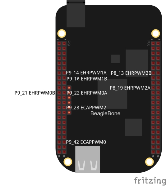
Here is a diagram that shows the available PWM pins on BeagleBone Black.