Though we have studied LEDs as digital devices, they are not actually digital devices. They emit light as per voltage put across them. If the voltage is high, they emit more light. If we provide an LED with a digital value, it will be ON or OFF. It will either light up with full brightness or not at all. If we provide intermediate values, it will still glow. But not with its full intensity. As we can apply any voltage between 0V to 3.3V using PWM on an LED now, we can change the brightness of the LED from lowest to highest and from highest to lowest. This will look like the LED is fading in and out.
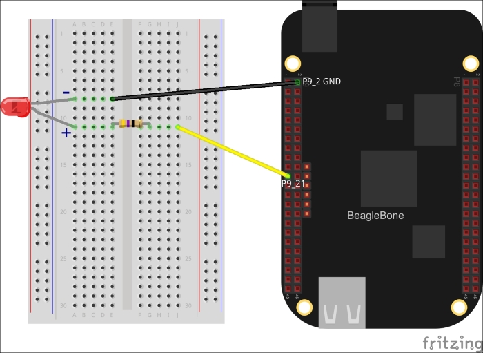
The circuit setup is similar to what we did in Chapter 3, Blinking External LEDs to blink external LEDs. At that time, we used P8_10 as the GPIO pin. Now we are connecting the LED to pin P9_21, which supports the PWM. You will need an LED, 470Ω resistor and a breadboard to set up this circuit. Power off the board and attach components to BeagleBone as shown in the diagram.