
BeagleBone has two expansion headers at both edges with 46 pins each. If you look carefully, you can see that headers are marked as P8, P9 and pins 1, 2, 45, and 46 are marked on the board. Not all extension pins are GPIOs. Some pins are reserved to deal with analog components. Some pins are power and ground pins. BeagleBone SRM and Schematic diagram give details of which extension pin is connected to which of the processor pin. Many sensors/components require an external power supply to operate. Power supply can be given to these sensors via power and ground pins. BeagleBone provides both 3.3 volts and 5 volts pins to power up sensors with that voltage level.
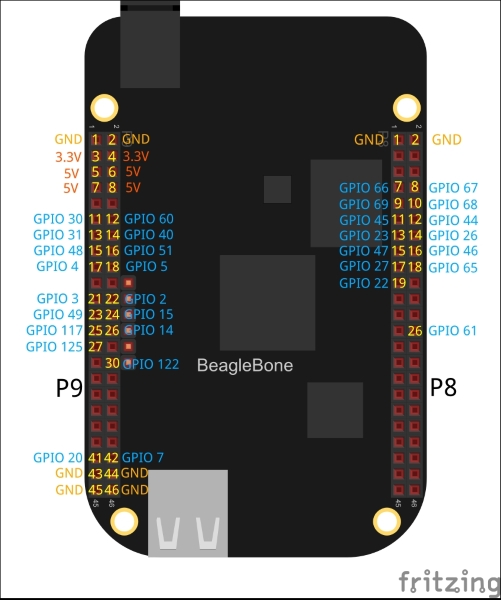
The AM335X processor has four banks of 32 GPIO pins each. Not all 128 pins are accessible. Some are used for a specific purpose like USER LEDs. Please refer to the image below to see the list of GPIOs available on extension headers of BeagleBone Black. A total of 32 GPIO pins are available to users on BeagleBone Black. BeagleBone White and BeagleBone Green have the same pins with some extra pins available for GPIO. The bone101 webpage seen in the Chapter 1, Cloud9 IDE gives a correct listing of GPIO pins for respective BeagleBone versions:
BeagleBone Black came with additional features of HDMI and emmc storage compared with old BeagleBone White. They needed some pins to communicate with the BeagleBone processor. Pins 3–6 and 20–25 and pins 27–46 on P8 headers were given to HDMI and emmc to communicate with the processor. Though it is not visible outside, these pins on P8 headers are shared with HDMI/emmc internally. That is why BeagleBone Black has a smaller number of GPIOs available than BeagleBone White and BeagleBone Green. Using pins that are internally connected to HDMI will cause the HDMI output to be disrupted. If you need to use more than 32 GPIOs, you can disable HDMI/emmc using a device tree and use freed pins. This is covered in the Appendix C, Pinmux and the Device Tree.
GPIO pins are an interface between the BeagleBone processor and the external world. Consider a USB-based fan attached to a desktop computer. In that case, communication is done from the processor to the USB controller and from the USB controller to the USB fan. Over-voltage and over-current damages the USB controller only. But when an LED is connected to a BeagleBone GPIO pin, communication happens directly in between the BeagleBone processor and LED. Over-voltage and over-current to these pins can damage the processor directly. Let's put the warning again.