
To set up a light dependent resistor (LDR) circuit, we'll need:
- LDR
An LDR is also called a photocell or photoresistor. It is special type of resistor. Its resistance decreases as it is exposed to light. The higher the light exposure, the lower the resistance. In a dark room, it has highest resistance. This property comes from physical characteristics of semiconductors used inside. LDR does not belong to a specific company. There is no official datasheet either. You can refer to this webpage for more information about LDR: https://learn.adafruit.com/photocells
- Male-to-male jumper wires
We need jumper wires to connect BeagleBone and components through a breadboard
- Half-size breadboard
A breadboard is needed to create solderless circuit
- 10KΩ resistor
A resistor is needed to create a voltage divider circuit
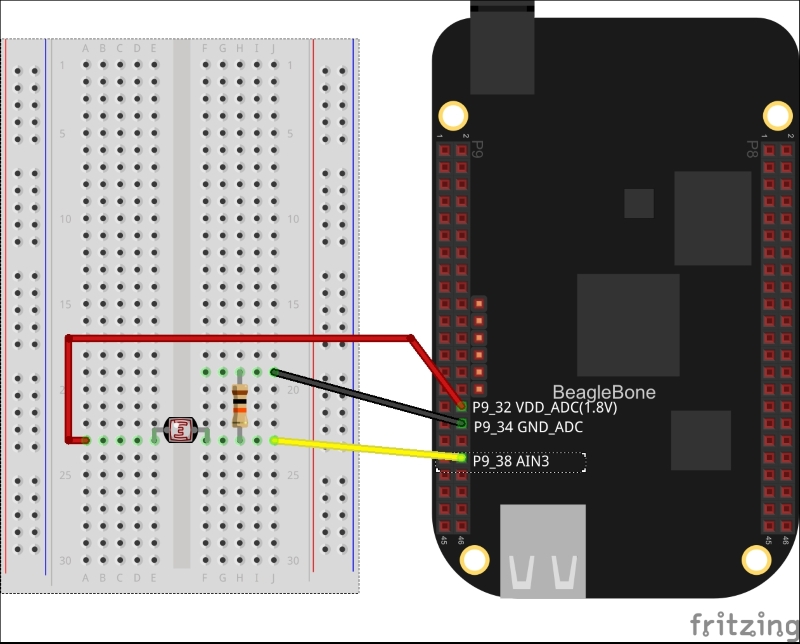
Power off the board and attach components to BeagleBone as shown in the following diagram:
The resultant circuit schematic looks like this:
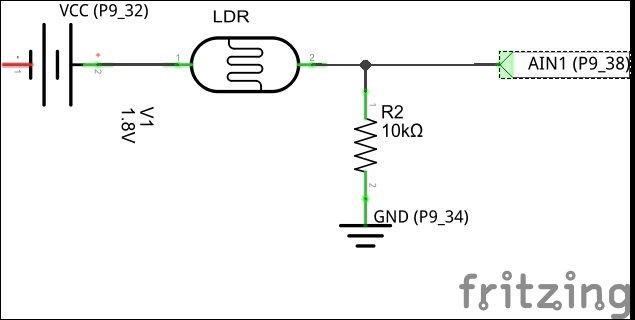
This circuit is a typical example of a voltage divider circuit. The input voltage is getting distributed among two routes reaching to ground/drain. Measuring light intensity through the LDR is easy. If the input voltage is applied on one end of the LDR, the other end will have measurable output voltage directly proportional to light intensity. When a 1.8V input is applied, the LDR scales the output voltage to the nearby input voltage value (close to 1.8V). There is a very small difference in output voltage generated by strong light and output voltage generated by low light. So, it becomes difficult to differentiate between high and low light intensity. Consider the preceding circuit without a R2 resistor and no GND pin P9_34. Then the voltage at P9_38 will be close to 1.8V even at low light and it will be difficult to detect a low light condition. This excessive output voltage has to be scaled down to be able to differentiate between light intensities. To reduce the magnitude of the output voltage, we added a R2 resistor connected to ground. This is called voltage dividing. Now, the circuit starts at one end but finishes at two different ends. The LDR output voltage is divided among two routes. Excess voltage passes through the R2 resistor. This reduced the voltage scales long range to distinguish low light and strong light situations. In our circuit, we have connected a 1.8V input voltage source at one end of the LDR. When the LDR is put in the dark, its resistance will increase and the output voltage at the other end will decrease. When the LDR is put near a bright light source, the resultant voltage at the other end will increase. BeagleBone reads that voltage on the P9_38 analog input pin. BeagleBone ADC converts that analog value to the nearest digital value. We will read this in our program using the analogRead() function. Let's write a program to do so.