
Let's write a program to dance LEDs in both directions like we did in the previous chapter. For this exercise, you will need:
- Seven LEDs: We are using seven LEDs to create a dancing pattern
- Male-to-male jumper wires: We need jumper wires to connect BeagleBone and components through a breadboard
- Seven resistor 400Ω–1kΩ: A resistor is needed to limit current flowing through an LED to protect it.
- Half size breadboard: A breadboard is needed to create a solderless circuit.
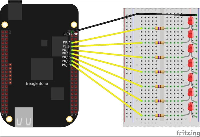
Power off the board and disconnect the power and USB cable. Then attach components to BeagleBone as shown in the previous diagram.
This circuit is the same as the last circuit repeated seven times. We used seven GPIO pins to connect seven LEDs through resistors. These pins are P8_7, P8_9, P8_11, P8_13, P8_15, P8_17 and P8_19. The negative end of all LEDs is connected to a single column. This column is connected to ground via P8_1 pin on BeagleBone. So, seven different positive ends are connected to common ground. When P8_7 pin is HIGH, the first LED will turn on. Then if P8_9 is turned HIGH and P8_7 LOW, it will look like the LED glow has shifted from the first LED to the second and so on.