
In the previous chapter, we read information from analog sensors. It is time to write information on analog devices like motors. Writing analog information is not that straightforward. The BeagleBone processor has a Pulse Width Modulation (PWM) subsystem that can write analog information on some specific GPIO pins. In this chapter, we will learn how PWM works and how it can be used to interface analog output devices. Then we will write a program to fade an LED and drive a servo motor using PWM. In this chapter, will cover the following topics:
- What is PWM?
- BeagleBone's PWM
- Writing on analog components
- Fading LED circuit setup
- Program to fade in and fade out an LED
- Micro servo motor circuit setup
- Program to control micro servo motor
Typically variable voltage is generated by analog circuits. Digital circuits generate only HIGH (3.3V) or LOW (0V) voltage. Digital microprocessors/microcontrollers cannot produce analog voltages themselves. They need a Digital to
Analog Convertor (DAC). We have seen in the previous chapter that BeagleBone has a built-in ADC that converts captured analog voltage to a value. This raises our hope that BeagleBone might have a DAC to generate analog output voltage. But this is not true. Instead of providing a DAC, it uses a mechanism called PWM, which achieves similar results. Some of the GPIO digital pins are driven by BeagleBone's PWM subsystem. It can generate any voltage inside the 0V to 3.3V range on these pins.
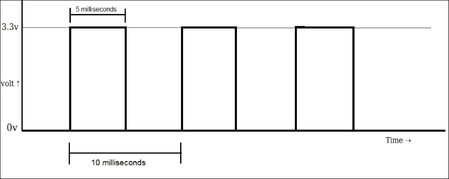
Suppose that we have connected an analog output device DC motor to one of the GPIO pins on BeagleBone (with capacitor filter). The speed of a DC motor changes proportionally to the voltage applied. The more voltage applied, the higher the motor speed. The connected GPIO digital pin can produce only 0V or 3.3V. Now, if we turn that GPIO pin ON and OFF very fast for an equal amount of time, the analog device will output as if it received half of the regular GPIO pin voltage, for example, if we turn the GPIO pin ON (3.3V) for 5 millisecond and OFF (0V) for the next 5 milliseconds and keep this pattern ongoing, the connected motor will rotate at a speed equivalent to the speed it rotates at 1.65V (half of 3.3V). At the same time, if you check the voltage between the pin and ground, you will see 1.65 reading on the multimeter. That means we got an average 1.65V output even if the GPIO pin is capable of producing only 0V and 3.3V.
If we plot a graph of Time versus Volt in the previous example, it looks like the following diagram. In this diagram, there are multiple square wave cycles generated periodically. One total wave cycle time is called a Period. Here, the period is 10 milliseconds. In one second, there will be 100 such periods or wave cycles. So, the frequency is 100Hz here. The time for which the GPIO pin was kept ON is 5 milliseconds. This is half of the total wave cycle time or period. The percentage ratio of the time pin was kept ON to a period is called the Duty Cycle. In this case, the duty cycle is 50%. It can be calculated by the following equation:
Duty Cycle Percentage = (Time pin is ON / Period) * 100
If we keep the period the same as 10 milliseconds and increase the time duration the pin was ON, then the duty cycle percentage will increase. The motor will have a 3.3 voltage supply for longer time than before. So, the average voltage will increase as well. The attached motor will spin faster than it was spinning before. Suppose we have increased the duty cycle up to 75%. The period is still 10 milliseconds. The frequency is still 100Hz. The time pin remaining ON is 7.5 milliseconds. In that case, we will get an output equivalent to 2.475V output on the analog circuit. If we increase the duty cycle further, we will get a more average voltage. But it will definitely be less than 3.3V. When the duty cycle is 100%, there will be no OFF time at all. We will get 3.3V voltage at the pin. This situation is the same as making that pin HIGH via digitalWrite(). If we decrease the duty cycle to less than 50% keeping the period fixed, we will get an average voltage between 0V and 1.65V. The 0% duty cycle will be the same as making that pin LOW via digitalWrite(). The average voltage can be calculated by the following equation:
Vavg = Vcc * Duty cycle
where Vcc = GPIO voltage level.
Thus by changing the duty cycle and keeping the period fix, we can simulate the output voltage inside the range 0V to 3.3V. This method of generating analog values on digital pins is called Pulse Width Modulation (PWM). The name fits because these waves look like pulses and we are changing/modulating width. We also conclude that the average voltage is directly proportional to the duty cycle. Most of the time, we specify the duty cycle rather than the average output voltage.
PWM is more efficient than DAC. No digital to analog conversion is done in a PWM generation circuit. So, it reduces the need for extra analog components. Digital pins are reused here. There is no need for extra pins for analog output. PWM uses less power and generates less heat than DAC. This eliminates the need for heat sink. Also, PWM implementation is cheaper than DAC. PWM can be used to control DC motors, position servo motors, and control the luminance of LEDs. It is used in remote control devices. PWM is used in telecommunications to encode-decode data. It can be used almost all the time when an analog output is needed. It can even be used to generate audio signals.