We are going to control a micro servo motor. Servo motors are special types of DC motors tightly coupled with a feed-backing control circuit that positions a shaft in a precise angle. They are used where fast, accurate, and limited angle movement is needed, for example, robot arm movement and CNC machine. The position of the motor shaft can be controlled through PWM. There is no need for extra motor driver chip.
A micro servo motor can rotate 180 degrees. The frequency/period is specific as per the servo motor. A typical servo motor expects approximately a 20 millisecond period to drive the motor. A servo motor changes shaft angle as per pulse width. If the specified pulse width is 1 millisecond or less, it remains at angle zero. That translates to approximately 3% duty cycle. If the pulse width is 1.5 milliseconds, then the servo shaft will change to a 90 degree angle. If a 2 millisecond pulse is given, the servo shaft will be at a maximum 180 degrees. It translates to a 14.5% duty cycle approximately. So, if we want to drive the servo motor, we have to specify a duty cycle value between 3% and 14.5%.
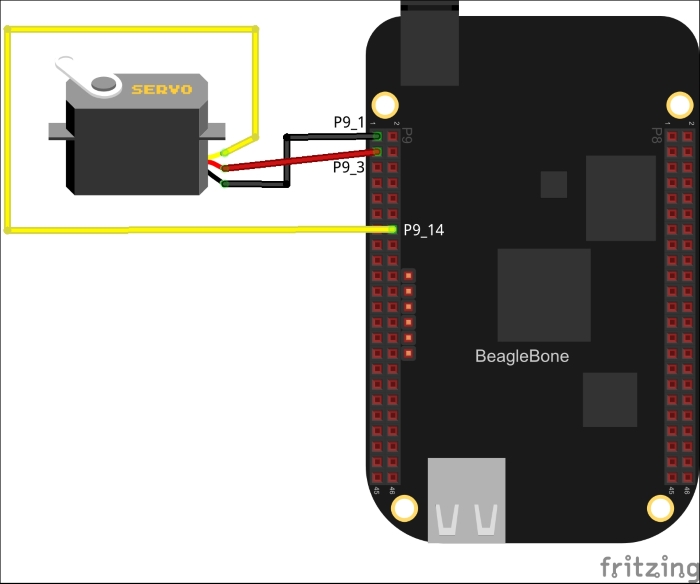
For this exercise, we need a micro servo motor. Power off the board and attach the components to BeagleBone as shown in the diagram: