
Chapter 5: Texturing Your Models inside Quixel Mixer
In Chapter 4, UV Maps and Texture Baking, you learned how to UV map and bake texture maps for three-dimensional (3D) assets, and you were also introduced to the concept of textures and materials.
In this chapter, we will explore the procedural-texturing process in detail.
First, you will go through a step-by-step tutorial to learn how you can utilize procedural-texturing methods to create texture maps for the Robot Drone model.
Then, afterward, you will be able to experiment by texturing the Alien Plant asset using your newfound procedural-texturing knowledge. Having this freedom to play with the various settings, instead of blindly following instructions to enter arbitrary numbers and using certain materials, helps you to really understand the software from a whole different perspective. Self-experimentation is one of the best ways to learn 3D.
But there may be those who feel more comfortable following step-by-step instructions, to understand how I got to the final result of my Alien Plant's textures.
If you fall into that category, you can download my tutorial titled Additional Content Volume 4 - Step-by-Step Texturing of the Alien Plant.pdf. You will find a link to this tutorial in the Further reading section of this chapter.
We will start this chapter by introducing you to the free procedural-texturing software called Quixel Mixer (also known as Mixer).
After your introduction to Mixer, we will start by texturing the Robot Drone and then texture the Alien Plant.
In this chapter, we're going to cover the following main topics:
- Introducing the basics of Quixel Mixer
- Texturing the Robot Drone in Mixer
- Texturing the Alien Plant in Mixer
- Exporting your materials for use in Unreal Engine 5 (UE5)
To complete the texturing tutorials for the Robot Drone and the Alien Plant, you need to use the provided 3D models and texture maps (instead of using your own).
Download the Robot Drone model and the Alien Plant model along with their texture maps from the online repository here: https://github.com/PacktPublishing/Unreal-Engine-5-Character-Creation-Animation-and-Cinematics/tree/main/Chapter05.
After you've completed the procedural-texturing tutorials in this chapter, you should revisit this chapter... but on your second visit, use your own textures, models, materials, and settings of your own choosing. The important part of this chapter is to learn the procedural-texturing techniques to enable you to texture all your own 3D assets in the future.
At the end of this chapter, you will have practical knowledge of how to procedurally texture your own 3D models. You will also be able to create your own material variations by using different textures, materials, masks, and variations of the settings I have used.
Let's first start with an introduction to Mixer, where you will learn the basics of the user interface (UI) and the most important shortcuts that we will use.
Technical requirements
You will need the following technical skills and software to complete this chapter:
- A computer that can run basic 3D animation software.
- A basic understanding of how to navigate and manipulate meshes in Blender. This was covered in Chapter 1, An Introduction to Blender's 3D Modeling and Sculpture Tools.
- You need to have installed Blender from https://blender.org/. The Blender version in this chapter is version 2.93.5. Even if your version of Blender is newer, the examples should still work without any problems.
- You need to have Quixel Mixer installed from https://quixel.com/mixer.
The files related to this chapter are placed at https://github.com/PacktPublishing/Unreal-Engine-5-Character-Creation-Animation-and-Cinematics/tree/main/Chapter05
Introducing the basics of Quixel Mixer
Quixel Mixer is a free procedural-texturing software. You can use it to create physically accurate materials for use in UE.
The materials that Mixer exports are set up to use a physically based rendering (PBR) workflow. This method of rendering materials emulates how light interacts with different kinds of surfaces. We can use PBR materials in real-time renderers such as UE or in offline renderers.
You can also create non-photorealistic textures in Mixer, where physical accuracy does not matter.
Now that you have an understanding of what Mixer is, install it on your computer. During your installation process, select the option to install all the six smart material packs.
In the next section, we will set up Mixer for your first project.
Configuring your project and Mixer file
When you launch Mixer for the first time, a Mixes menu window will open. In the following screenshot, I have highlighted important areas you need to focus on:
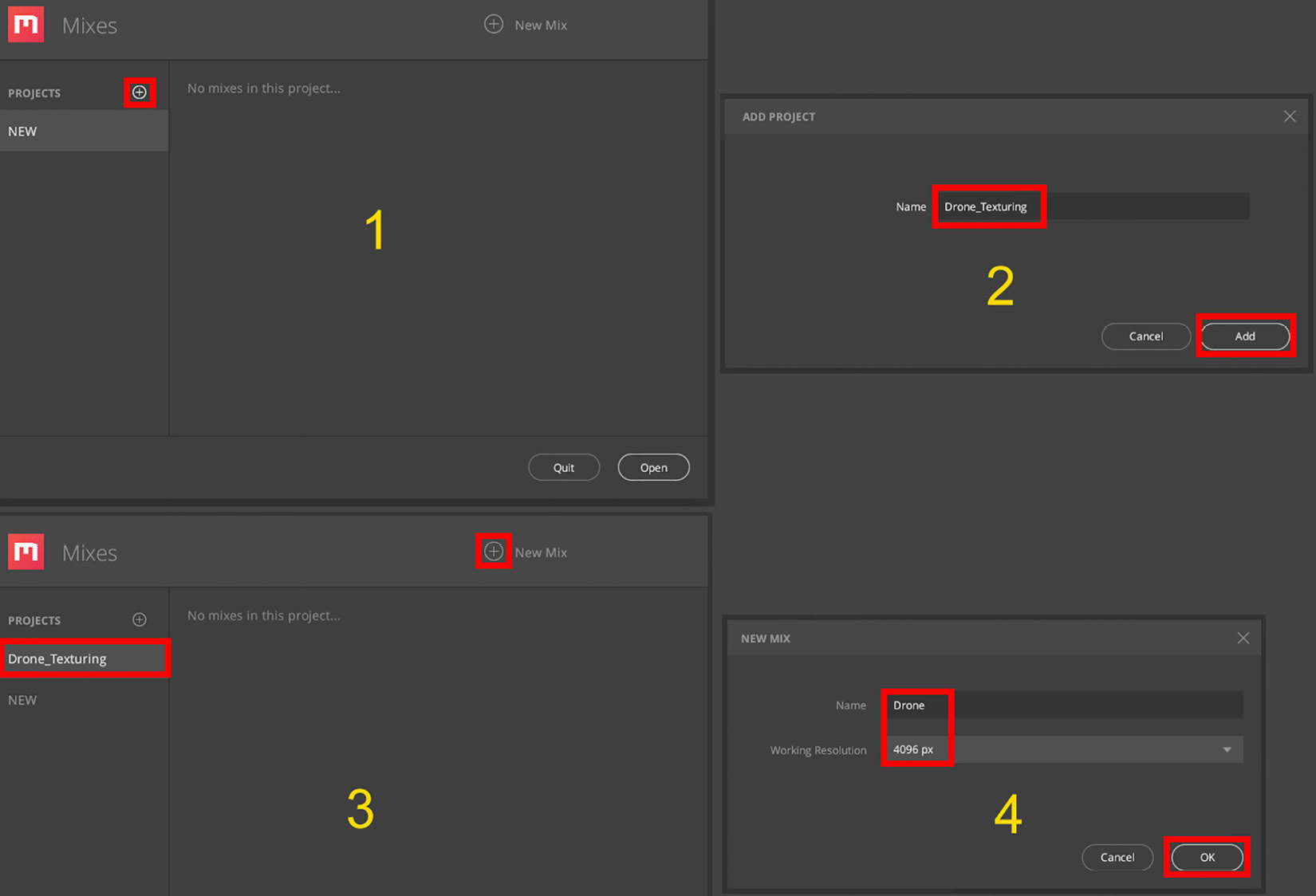
Figure 5.1 – Configuring your project and Mixer file
Execute the following steps to configure your project and Mixer file:
- You will see PROJECTS, with a + icon highlighted in red, on the left side of the window. Click on this + icon.
- An ADD PROJECT window will open up. Name the project Drone_Texturing. Now, click on Add to add this project.
- You will see that a Drone_Texturing title has been added underneath PROJECTS. Click on the + icon next to NEW MIX (a mix is a Quixel Mixer file).
- A NEW MIX window will open up. Name your mix Drone and set the Working Resolution value to 4096 px. Click on the OK button to open your new Mixer file.
You have successfully configured your project and Mixer file. In the next section, we will take a brief look at the UI layout of Quixel Mixer.
Quixel Mixer's UI and shortcuts
Quixel Mixer will now open, and you will see a screen like the one shown next, but without the white wording, yellow numbers, and red highlights (these were added to explain the UI).
By default, a 3D-plane model is loaded when you launch Mixer for the first time:
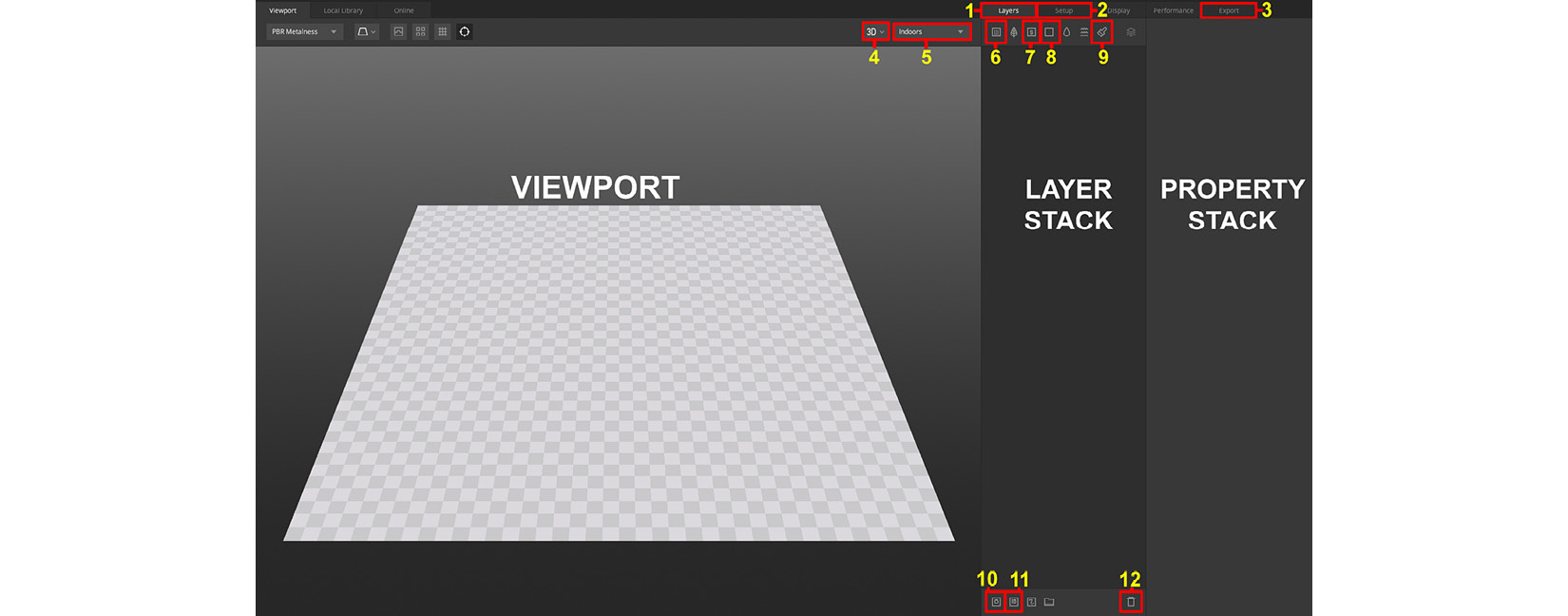
Figure 5.2 – The UI of Quixel Mixer with the 3D plane inside the Viewport
In Figure 5.2, you can see the UI of Mixer. I have highlighted and numbered all the items that we will use in this chapter. Let's have a look at these areas in more detail:
- Viewport: This is where you will view the 3D assets you are working on.
- Layer stack: This area will display layers of surface and smart materials.
- Property stack: Adjustable properties will be shown here. Also, you can add Mask components and Mask modifiers here and edit them.
The numbered icons in Figure 5.2 correspond to the following:
- Layers tab
- Setup tab
- Export tab
- 3D View Mode and 2D View Mode drop-down menus
- Image-based lighting drop-down menu
- Add Surface Layer
- Add Smart Material
- Add Solid Layer
- Add Paint Layer
- Add Mask stack on this Layer
- Add Material ID on this Layer
- Delete Layer/Mask
To get started, here are the shortcuts that we will use for our tutorial:
- Mixer's Viewport navigation shortcuts are listed here:
- Rotate the view: Alt + left mouse button
- Pan the view: Alt + middle mouse button
- Zoom in/out: Alt + right mouse button (or use the mouse wheel)
- Other shortcuts are listed here:
In this section, you've learned about basic UI regions and now know the locations of icons we will use, as well as shortcuts we will use.
In the next section, we will load the Robot Drone model and start to texture it.
Texturing the Robot Drone in Mixer
Before you start on the texturing tutorial, you need to familiarize yourself with the way that lighting works in Mixer.
Try out the following shortcut in Quixel Mixer's Viewport: Shift + right mouse button to rotate the image-based lighting.
Also, try out different image-based lighting options in the drop-down menu (see numbers 4 and 5 in Figure 5.2). This step is essential since you will need to see the results of your textures/materials under different lighting angles and conditions.
Let's now get started with the practical part of our tutorial, by loading your model into Mixer.
Loading the Robot Drone model into Quixel Mixer
The first thing you want to do in Quixel Mixer is to replace the 3D-plane model shown in Figure 5.2 with your own custom model. In the following screenshot, I have added images of the Setup tab's menu:
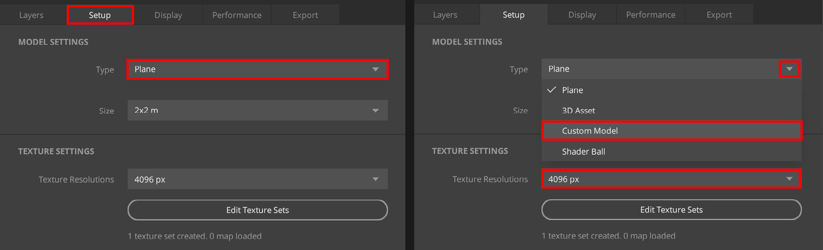
Figure 5.3 – Loading a custom model into Quixel Mixer
We will now go through all the steps to load your own custom model file, as follows:
- Click on the Setup tab, as shown in Figure 5.3.
- In Figure 5.3, you will see that Plane is listed as the default type of model that is loaded into Mixer.
- Click on the Type drop-down menu, and select Custom Model.
- Click on Custom Model. A Select model file window will open up. In this window, select the model file as RobotDrone.fbx, which you will find in the online repository here: https://github.com/PacktPublishing/Unreal-Engine-5-Character-Creation-Animation-and-Cinematics/tree/main/Chapter05.
The 3D-plane model will now be replaced by the Robot Drone model.
You've just learned how to add your own custom model to Mixer. In the next section, we will see how you can add your texture maps to Mixer.
Adding texture maps
Now that you've loaded the Robot Drone model into Quixel Mixer, we can go to the next step of the preparation process, which is to add the texture maps that you've baked in xNormal into the software.
As explained before in the Understanding texture baking section of Chapter 4, UV Maps and Texture Baking, Quixel Mixer refers to these texture maps as base maps.
Important Note
Although I've shown you how you can bake your own texture maps in Chapter 4, UV Maps and Texture Baking, for this chapter's texturing tutorials, you will need to use the texture maps I have provided.
Download the following texture map files: RobotDrone_Normals.tga, RobotDrone_AO.tga, RobotDrone_Curvature.tga, RobotDrone_Material_ID.png, and RobotDrone_Lines.png from the online repository here: https://github.com/PacktPublishing/Unreal-Engine-5-Character-Creation-Animation-and-Cinematics/tree/main/Chapter05.
The reason you need to use the provided texture maps is because you are using my material ID maps for these tutorials, and in the tutorial's steps, I refer to specific colors that you need to pick. This is not possible if you are using your own material ID maps.
The way we will add base maps to Quixel Mixer is by using its Texture Sets Editor feature. In the following screenshot, I have highlighted the areas of Texture Sets Editor that are important for this section:
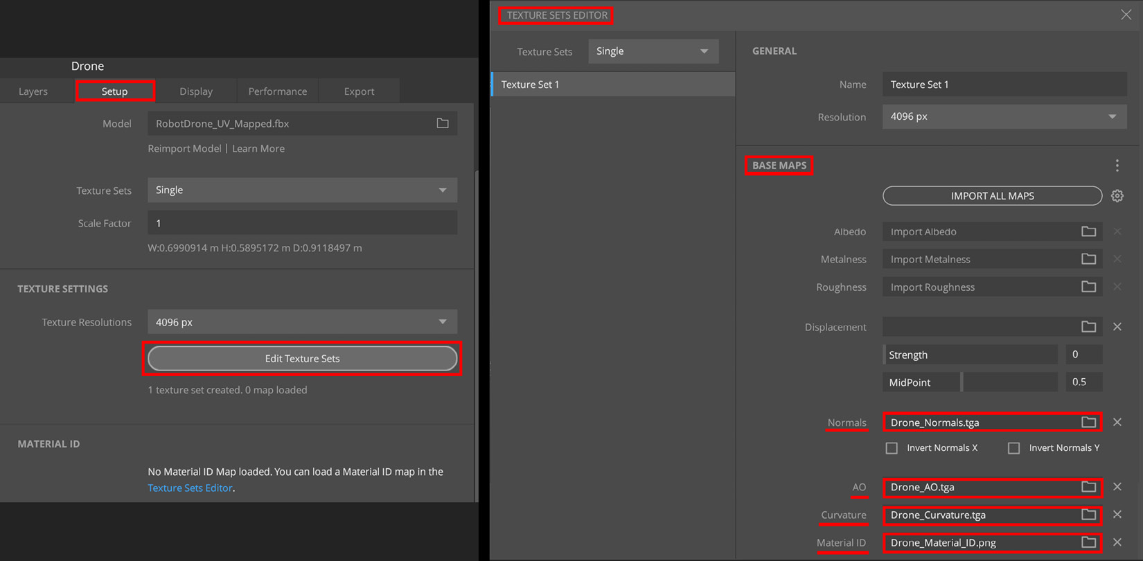
Figure 5.4 – Adding base maps to your model: (A) the Setup tab; (B) Texture Sets Editor
We will now go through the steps to set up your base maps, as follows:
- Click on the Setup tab. I have highlighted this tab in Figure 5.4.
- Click on the Edit Texture Sets button. A TEXTURE SETS EDITOR window will open up, as shown on the right side of Figure 5.4.
- We need to load all of the base maps into their respective slots in the TEXTURE SETS EDITOR window. Under the BASE MAPS heading, assign the corresponding texture maps for the Normals, AO, Curvature, and Material ID slots by clicking on the file icon and choosing a file from your hard drive.
- You've now set up all of your base maps. Close the TEXTURE SETS EDITOR window by clicking on X. in the top-right corner.
By default, any newly loaded model in Quixel Mixer will not have any textures or materials assigned to it, so you will notice that a checker pattern texture is currently displayed on the model's surface, as can be seen in the following screenshot:
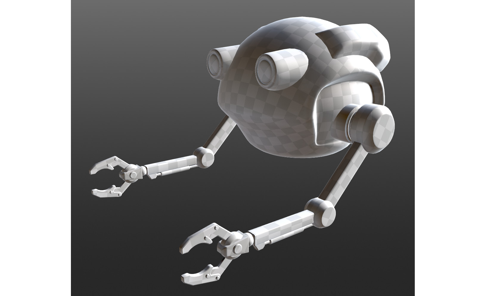
Figure 5.5 – The Robot Drone displayed with a checker pattern texture
That's it! The base maps and the project are all set up, and you are now ready to start your texturing tutorial.
Adding paneling details
Let's add some paneling details to the model. Paneling refers to the edges of mechanical parts, where they join up. Follow these next steps:
- We will use Drone_Lines.png. (the texture that you already downloaded in the previous section). This is a texture that I have painted with black lines. Mixer will use this texture to create paneling details.
- Click on the Layers tab.
- Next, click on the Add Solid Layer icon. I have highlighted this icon in Figure 5.6. You will see that the model's surface will change to a light gray color.
- In the Property stack, click on DISPLACEMENT to open a drop-down menu, then click on Load and select the Drone_Lines.png file. The process is illustrated in the following screenshot:
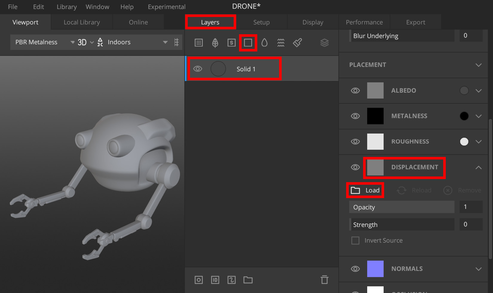
Figure 5.6 – Adding a solid layer and a displacement map
- Still inside the Property stack, click on NORMALS (as can be seen in the bottom-right corner of Figure 5.6) to open a drop-down menu.
- Check the Generate from Displacement checkbox to allow Mixer to use the displacement map (the texture with black lines) as a normal map, as seen in the following screenshot:

Figure 5.7 – Turning on the Generate from Displacement option
Normal mapping is a technique that is used to fake the lighting of bumps and dents inside a texture map. You will notice that as soon as you have completed this step, indented lines will appear all over the model's surface.
- In the Property stack, click on Placement to open a drop-down menu.
- In the PLACEMENT menu, click on Box Projection, then in the drop-down menu, select Tiling, as shown in the following screenshot. This will project the normal map lines to match the original hand-painted black lines texture, as seen in Figure 5.9, Part A:

Figure 5.8 – Setting the placement to Tiling
Rotate the lighting and the model in the Viewport to observe how the indented panel lines look. The panel lines are adding visual interest to the Robot Drone (to make it look more sci-fi-like).
Your model should now resemble the model shown in Part B of the following screenshot:
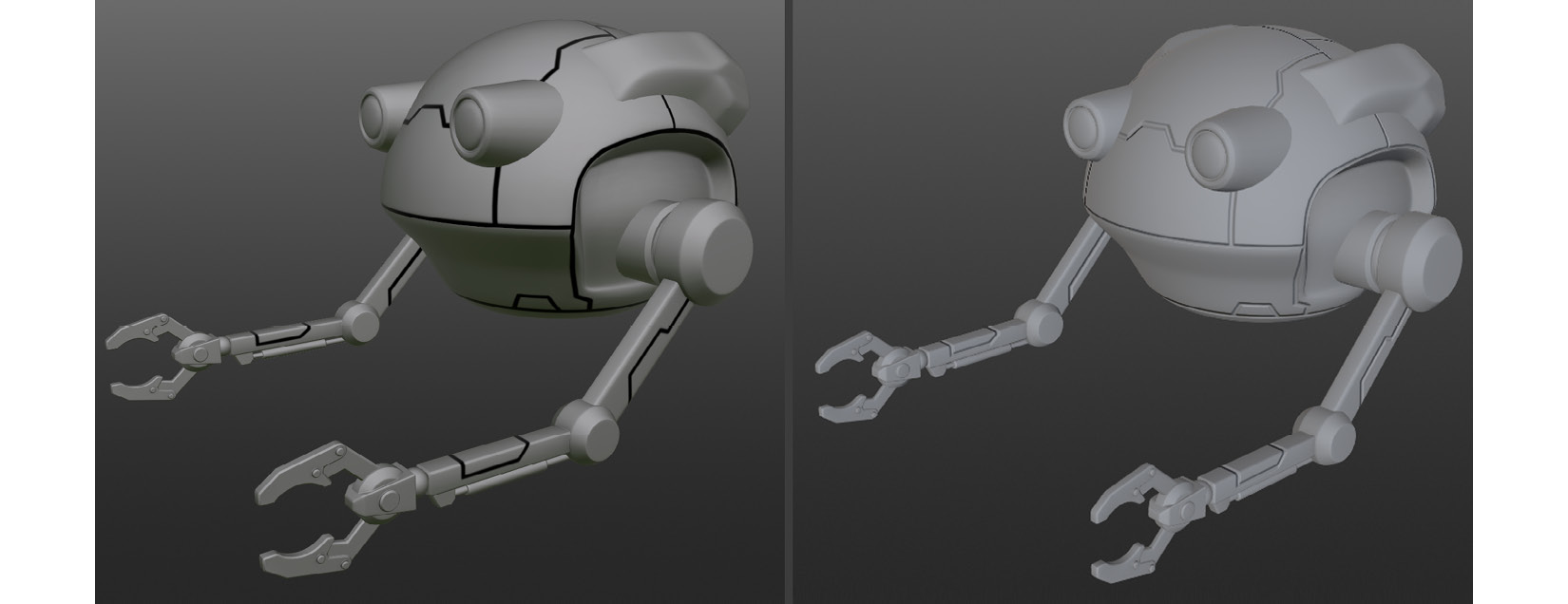
Figure 5.9 – (A) With black lines texture; (B) Black lines as a normal map for paneling
Note
Learn how to create your own paneling details by learning to paint line textures in Blender. To learn this skill, read the following document that I have created: Additional Content Volume 3 - Painting Lines in Blender.pdf (a link is provided in the Further reading section of this chapter).
Now that the normal map panel lines are set up, we can continue to work on the different layers of textures and materials.
Texturing the Robot Drone
The Robot Drone model is now ready for the procedural-texturing stage.
We will create the Procedural Textures by adding various Layers of Textures, Smart Materials, Paint Layers, Surface Layers, and Masks to the model inside of Quixel Mixer. All these various layers work together to create a final material that we will export into UE later.
Let's add the first surface layer, as follows:
- Click on the Add Surface Layer icon. This will open up the Local Library tab that displays a variety of surface materials (I have highlighted the Local Library tab in Figure 5.10, Part A). Let's look at some terms in more detail:
- Local library: This is a library that shows you assets that are currently available on your own (local) hard disk drive.
- Online library: This is a library that shows you assets that are currently available to download from Quixel Mixer's server (on the internet).
- Surface: This is a type of material in Quixel Mixer and it contains multiple textures.
You can see an overview of the Local Library and Online tabs in the following screenshot:
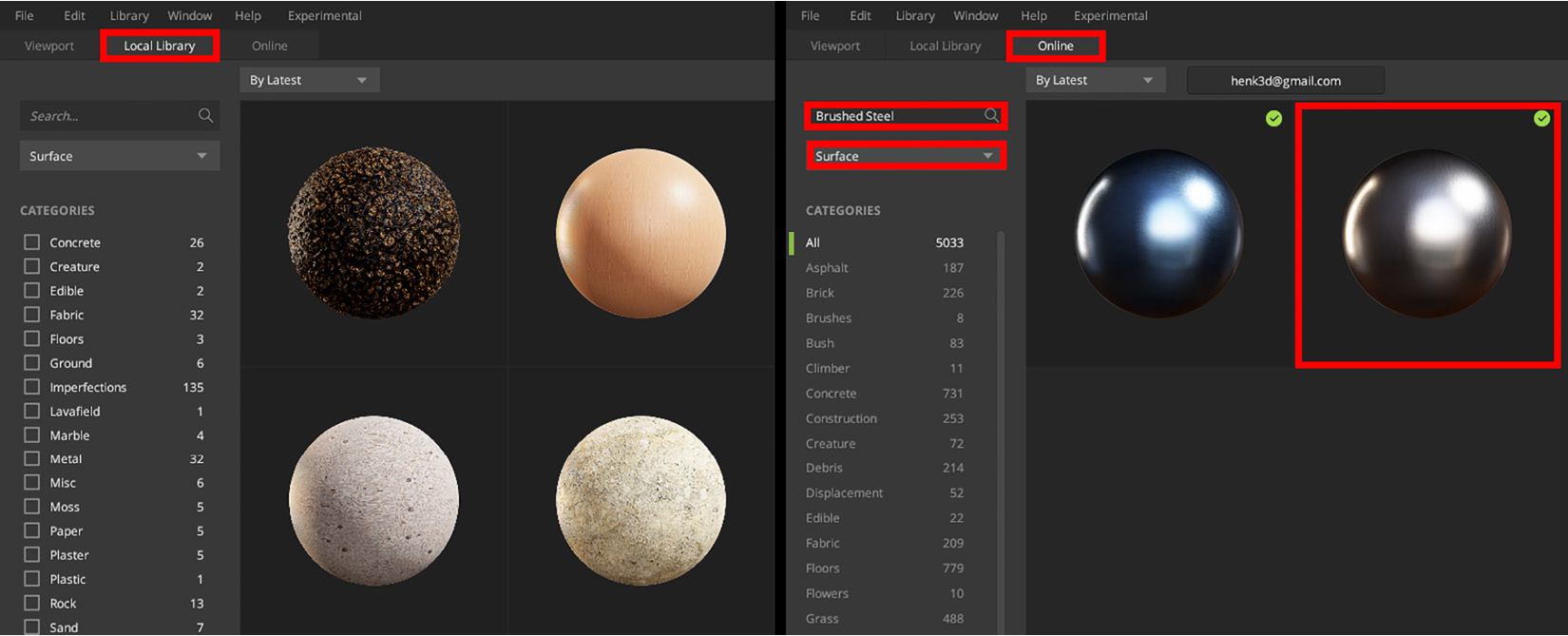
Figure 5.10 – (A) Local Library tab; (B) Online tab
- The surface you need to use can be found in the Online library. Let's take a look at how to use this Online library. In Figure 5.10, Part B, you will see that I've highlighted the Online tab. This tab shows you a library of available assets (surfaces, smart materials, and so on) that are on Quixel Mixer's server.
- In Figure 5.10, Part A, you will see a search box. In this search box, type in Brushed Steel. Below this search box is a drop-down menu. Set this to Surface, as can be seen in Figure 5.10, Part B.
- After you've typed in your search, press Enter. Two surfaces (icons of metallic spheres) will appear on the right side. Select the Brushed Steel surface that's highlighted in Figure 5.10, Part B.
Note
The name of the surface will appear when you hover your mouse pointer over the surface icon.
- Click on the surface icon. Another window will pop up with a button to download the surface material. Download the Brushed Steel surface to your local library now.
- You've just applied your first surface material (the Brushed Steel surface) in a layer. In the Property stack, click on PLACEMENT, as shown in Figure 5.11.
- In the PLACEMENT part of the Property stack, set the Scale value to 2.5 to make the brushed effect more visible to the eye, as shown in the following screenshot:
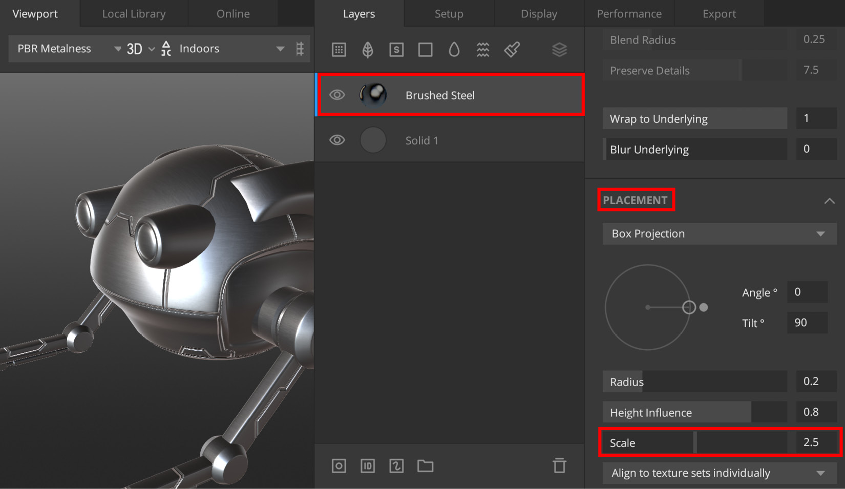
Figure 5.11 – Adjusting the scale of the Brushed Steel surface's grain
- Still inside the Property stack, scroll down until you see a section that lists different material components (ALBEDO, METALNESS, ROUGHNESS, and so on) of the surface material. These components are shown in Figure 5.12, Part A. The first component is ALBEDO. You will see a small circle icon displayed next to each of the material components (highlighted in Figure 5.12, Part A). Click on the circle icon next to ALBEDO.
- A SELECT ALBEDO COLOR menu will open up. Set the value for Red to 87, Green to 87, and Blue to 87, as shown in Part B of the following screenshot:
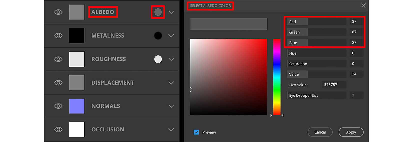
Figure 5.12 – (A) List of material components, with ALBEDO and the circle icon highlighted; (B) SELECT ALBEDO COLOR menu
- Now that you know how to select colors (or black and white tones), do the same for ROUGHNESS. Set the value for Red to 98, Green to 98, and Blue to 98.
- Let's now create a third layer for our procedural-texture material. Click on the Add Solid Layer icon. Set ALBEDO as follows: Red to 94, Green to 93, and Blue to 92. This layer will represent the paint that covers the metal surface on parts of the drone. At this moment, the paint covers the entire drone.
- We will now add some edge wear around the sharp edges of the drone's surface. To do this, we will use a mask. Click on the Add Mask Stack on this Layer icon,or you can use the K shortcut key. You have just added an empty mask to your layer, as shown in the following screenshot:
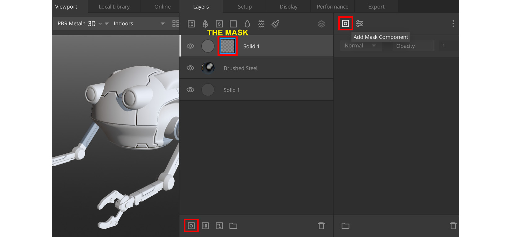
Figure 5.13 – Adding a mask stack to the solid layer, then clicking the highlighted icon to add a mask component to the Property stack
- Click on the mask in the solid layer, then in the Property stack, click on the Add Mask Component icon (the highlighted icon at the top right in Figure 5.13).
- As soon as you've clicked on the Add Mask Component icon, a drop-down menu will appear, and in there, select Curvature. This will add Curvature settings to the Property stack.
How Do Curvature Maps Work?
Quixel Mixer uses curvature maps to calculate the convexity/concavity of a mesh. A curvature map is a texture map that assigns a grayscale value to sharp edges and cavities on your mesh. This information is used for procedural texturing. A mesh with a convex surface usually has sharper edges (peaks), while concave surfaces have cavities or indentations.
Mixer uses an algorithm that determines that sharper edges on the surface will automatically get more wear and tear (and, usually, more chipped paint) while blunt edges on the surface will get less wear and tear. A curvature map is also used to determine if there are cavities or indentations that need to be filled with dirt, oil, and so on.
- In the Property stack under the Curvature menu, click on Default Curvature, and in the drop-down menu, change it to Edges & Cavities, as shown in the following screenshot:
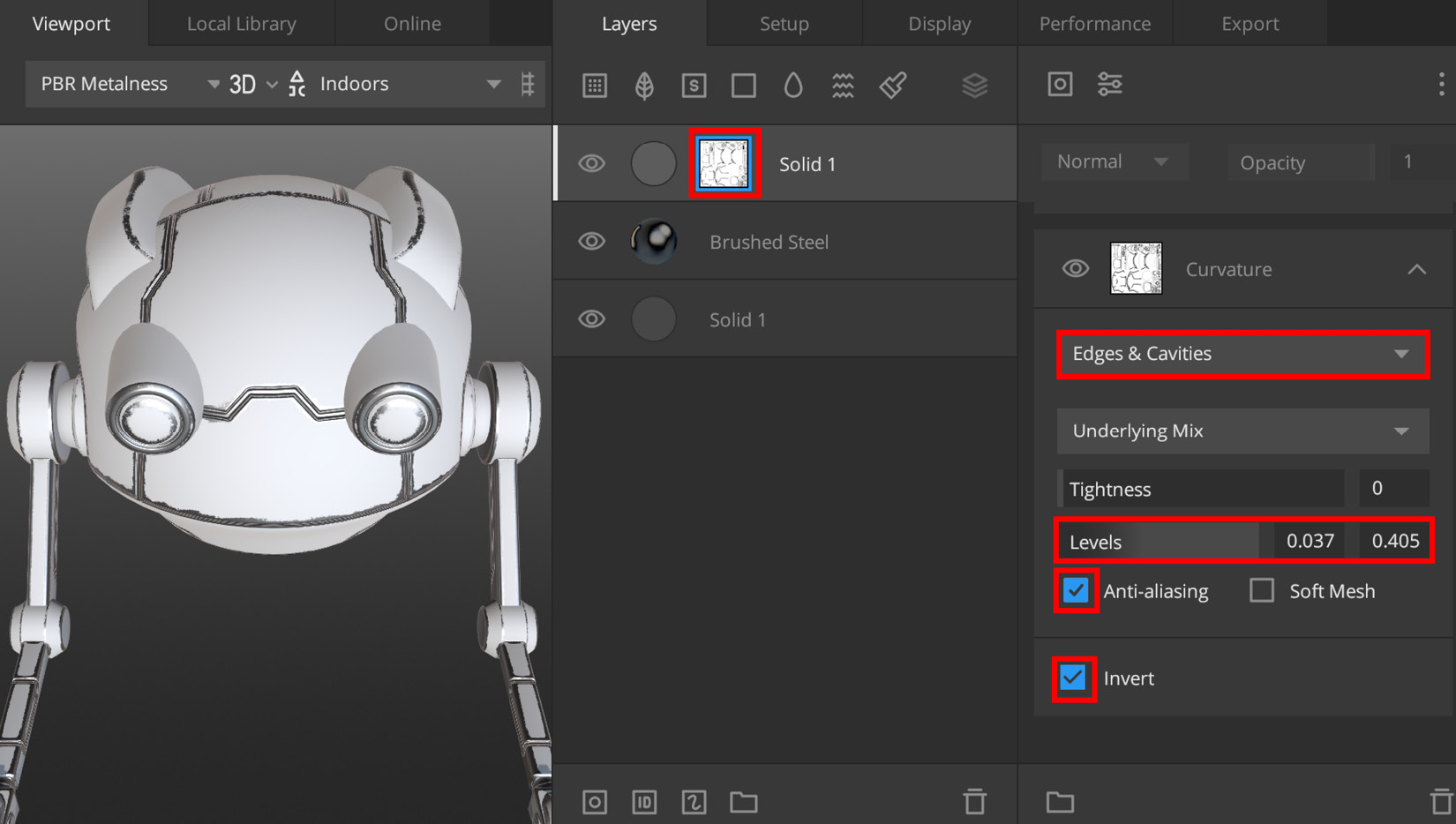
Figure 5.14 – Adjusting the curvature settings of the mask component
- Change the Levels setting to 0.037 (in the first box on the left side) and to 0.405 (in the second box on the right side). This adds very smooth edge wear around all the sharp edges of the model's surface, as seen in Figure 5.14.
- Check both the Anti-aliasing checkbox and the Invert checkbox. Now that the curvature mask component has been inverted, the paint is displaying the way it should. The paint is now covering the smoother and flatter areas while the paint has been masked on the sharper edges.
- Next, we want to add some noise to break up the edge wear, since it looks too smooth at this moment. Click on the Add Mask Component icon that you used earlier in Step 13 of this section, but this time, select Noise, and in the window that opens on the right, select Simplex as the Noise type, as shown in Figure 5.15, Part A.
- In the Property stack, inside the Noise menu, there are six inputs you need to change, as follows: set the Seed value to –29, Amplitude to 1.66, Frequency to 7.1, Octaves to 5, Lacunarity to 3.5, and Persistance to 1, as shown in Part B of the following screenshot:
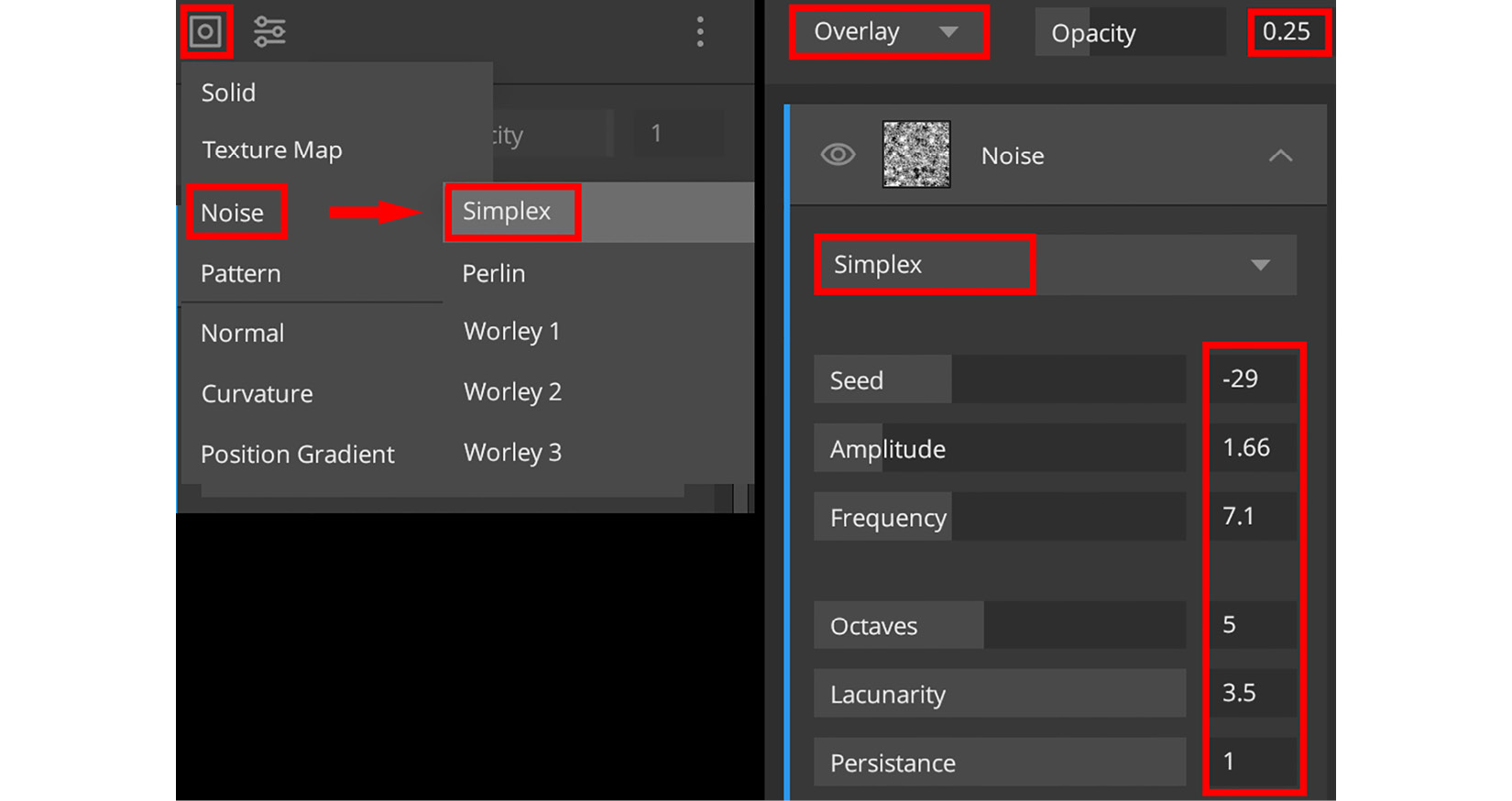
Figure 5.15 – (A) Adding a Simplex type noise mask component; (B) Settings for noise in the Property stack
- Directly above the Noise menu, you will see Normal (this is the blending mode) and Opacity (changes how much of the effect is used). Set Opacity to 0.25.
- Click on Normal, and in the drop-down menu, set Overlay as the new blending mode, as shown in Figure 5.15, Part B.
- Now, we will add some contrast to the noise on the edges to make it look more like chipped paint. Click on the Add Mask Modifier icon (I have highlighted this icon in bright green in Figure 5.16). In the drop-down menu that opens up, select Brightness/Contrast.
- In the Property stack, inside the Brightness/Contrast menu, set Brightness to –1 and Contrast to 8. You've just completed your Chipped Paint Edge-Wear layer, as can be seen on the model in the following screenshot:
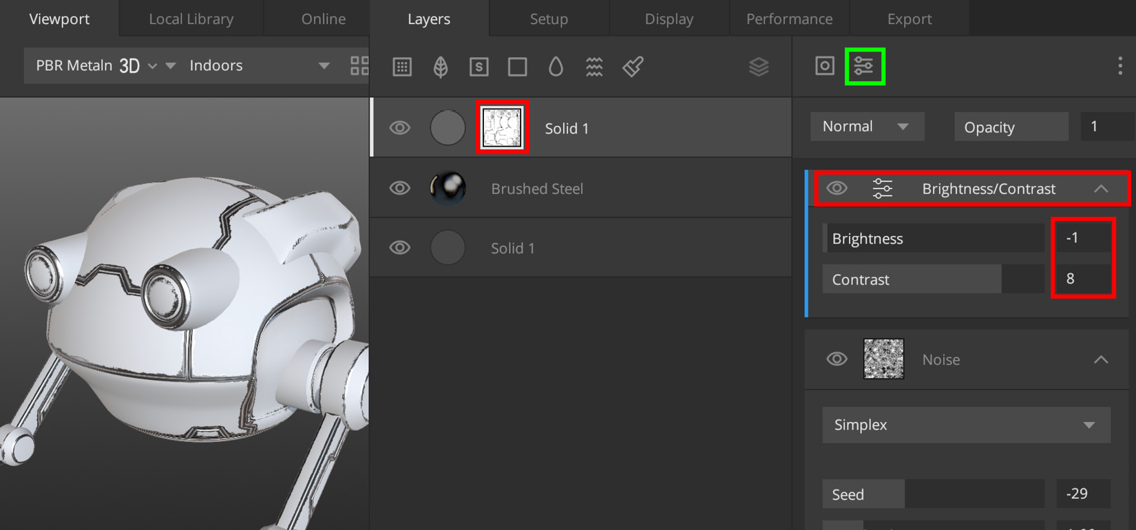
Figure 5.16 – Adding a Brightness/Contrast Mask modifier, and the settings used
- Now, we will add a type of material that is known as a smart material in Mixer. This kind of material is usually made up of different layers, and each layer can have its own procedural masks that can act on the base maps of your model. To complete this step, click on the Add Smart Material icon (I have highlighted this icon in bright green in Figure 5.17).
- This will open the Local Library tab, with the Type set to Smart Material. In the search box, search for Brass (Oxidized). This smart material is included inside Smart Materials Pack 2. In Figure 5.17, you can see that I have applied this Brass (Oxidized) smart material to the model, and you can also see that this smart material contains four layers inside it.
The whole Robot Drone's surface will now be replaced by this smart material layer. In the Layer stack, click on the Brass (Oxidized) folder to open a drop-down menu, as illustrated in the following screenshot:
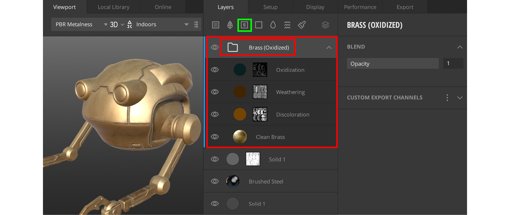
Figure 5.17 – The Add Smart Material icon highlighted in green, and the smart material with its layers highlighted in red
- We will now change a few settings to customize this smart material. Inside the Brass (Oxidized) folder, you will see a flat brown circle icon in the layer named Weathering.
Note
A circle icon that's rendered with a flat color means it is a solid layer. Click on the circle icon to open this solid layer's properties in the Property stack. Change the ALBEDO setting as follows: Red: 47, Green: 28, and Blue: 4.
- Inside the Brass (Oxidized) folder, click on the gray-colored circle icon in the layer named Discoloration. Then, in the Property stack, change the ALBEDO setting as follows: Red: 67, Green: 69, and Blue: 69. The gray-colored circle will now turn to a light brown color, as shown in Figure 5.17.
- Inside the Brass (Oxidized) folder, click on the spherical icon in the layer named Clean Brass.
This layer is a surface. In the Property stack, change the ALBEDO setting as follows: Red: 70, Green: 79, and Blue: 80. You have completed the customization of the Brass (Oxidized) smart material.
Your model should now resemble the one shown here:
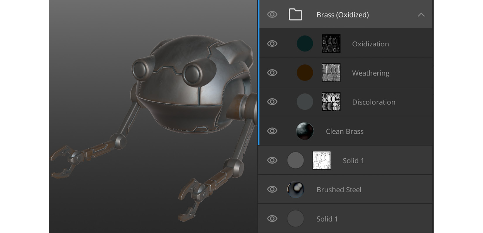
Figure 5.18 – The result of the modified Brass (Oxidized) smart material
Let's have a quick recap of what you have learned so far in this section, as follows:
- Added surface materials, solid layers, and smart materials
- Adjusted material properties by using the Property stack (panel)
- Used masks and curvature maps to create edge wear in materials
- Learned how to use noise in the Mask component
As you can see from Figure 5.18, the new smart material is covering the entire Robot Drone model. This is not what we want, so in the next section, I will introduce a way that you can apply any of your materials to selected parts of your model.
Using material ID maps and masks
A material ID is a unique color value. You can use material ID maps to assign materials to specific areas on your mesh (these areas are defined by their unique color values in a texture map). Let's take a quick look at the terminology, as follows:
- Material ID maps are textures that are composed of unique colors that specify areas on a mesh.
- Material ID masks are masks used by Quixel Mixer to enable you to pick unique color areas on your material ID map.
- Material ID maps and material ID masks always work together. Having different materials applied to different parts of your model makes it look much more visually interesting.
Note
Learn how to paint your own material ID map textures in Blender by completing Additional Content Volume 2 - Creating Material ID Maps.pdf (a link is provided in the Further reading section).
In the previous section, you applied a Brass (Oxidixed) smart material all over your entire Robot Drone model. This is not what we want, of course. So, in this section, I will show you how you can assign a smart material or surface to a specific part of your model.
The way we will do this is by using a material ID mask.
Let's go through the steps to apply a material ID mask to your Brass (Oxidized) smart material, as follows:
- Select the Brass (Oxidized) folder. Click on the Add Material ID on this Layer icon. This adds a blank material ID mask to the Brass (Oxidized) layer.
- Click on Material ID Mask in the Layer. This will open the material ID mask color selector in the Property stack, with checkboxes for each color. Select the same colors that I selected in Figure 5.19.
An alternative way to select material ID colors is to click and hold the Q shortcut key, which will temporarily change the Viewport to display the material ID color areas on the 3D model, as seen in the following screenshot. Left-click on a color part of the mesh that you want to assign your material to:
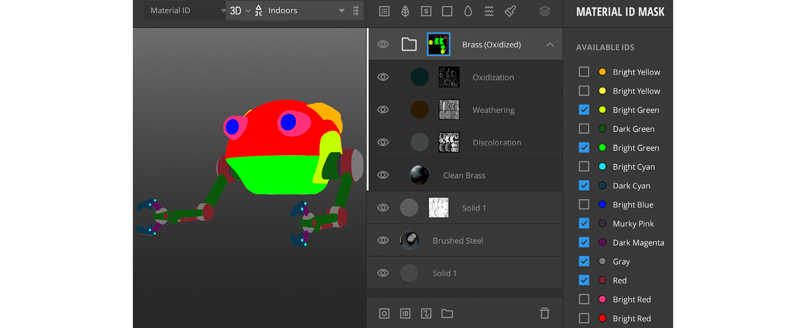
Figure 5.19 – Holding the Q button to select a material ID color on the model
In Figure 5.20, Part A, you can see how the model looked with the smart material applied all over it. In Part B of the following screenshot, you can see the result of using a material ID mask. As you can see, the smart material is now only applied to specific areas on the model:
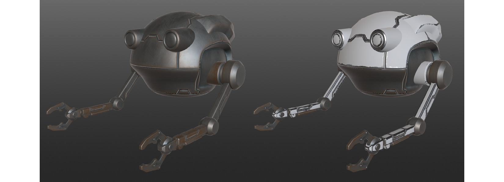
Figure 5.20 – (A) The model with the smart material over all its surface; (B) The model using a material ID mask to limit the smart material to certain areas on its surface
Next, let's add some rust inside the grooves of the paneling lines, to make it look as if the Robot Drone has been subjected to rainy weather for many years.
- Click the Add Surface Layer icon. Switch to the Online Library tab and select Surface as the type of asset, then search for Rusted Metal Sheet. Download this surface and click on its icon. This will apply a rust coat material over the entire model.
- With the Rusted Metal Sheet layer selected, look under Placement in the Property stack and change the Scale value to 0.69, as seen in the following screenshot:
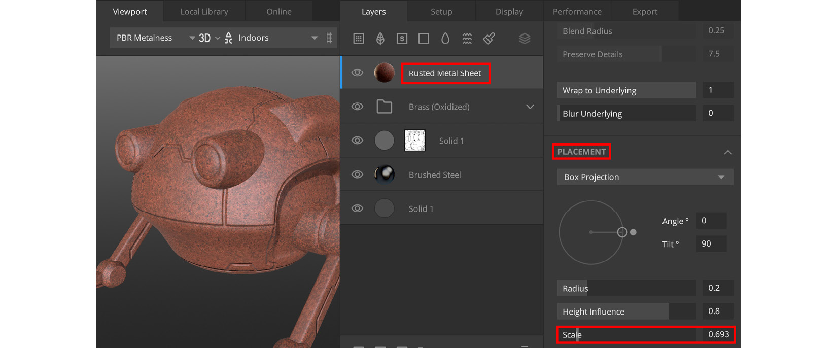
Figure 5.21 – Changing the scale of the surface material
- With the Rusted Metal Sheet layer still selected, look under Blend in the Property stack and change the Opacity value to 0.85.
- With the Rusted Metal Sheet layer selected, click on the Add Mask Stack on this Layer icon.
- Select the mask you have just added. In the Property stack, click on the Add Mask component icon, and in the menu that opens up, choose Curvature.
- In the Curvature menu, set the Edges & Cavities setting's Levels values to 0.27 and 0.825 and check the Anti-aliasing checkbox, as illustrated in the following screenshot. This has added some rust inside the paneling lines:
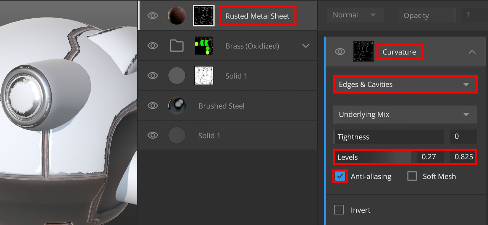
Figure 5.22 – Curvature settings for the Rusted Metal Sheet surface
- We're now ready to add some dirt to the model since it looks far too clean at this moment. Click on the Add Solid Layer icon. This solid layer can be seen in Figure 5.23.
- Change this solid layer's ALBEDO settings as follows: Red: 20, Green: 7, and Blue: 2. Set Roughness to Pure White. Under Blend, change the Opacity value to 0.438.
- Press the K shortcut key to add a mask stack to this layer, and then click on the mask that you've just added, which can be seen in Figure 5.23.
- With the mask selected, in the Property stack, click on the Add Mask Component icon and choose Texture Map as the option. The Texture Map properties can be seen in Figure 5.23.
- In the Texture Map menu, change Custom Map to Library Asset in the drop-down menu, as illustrated in the following screenshot:
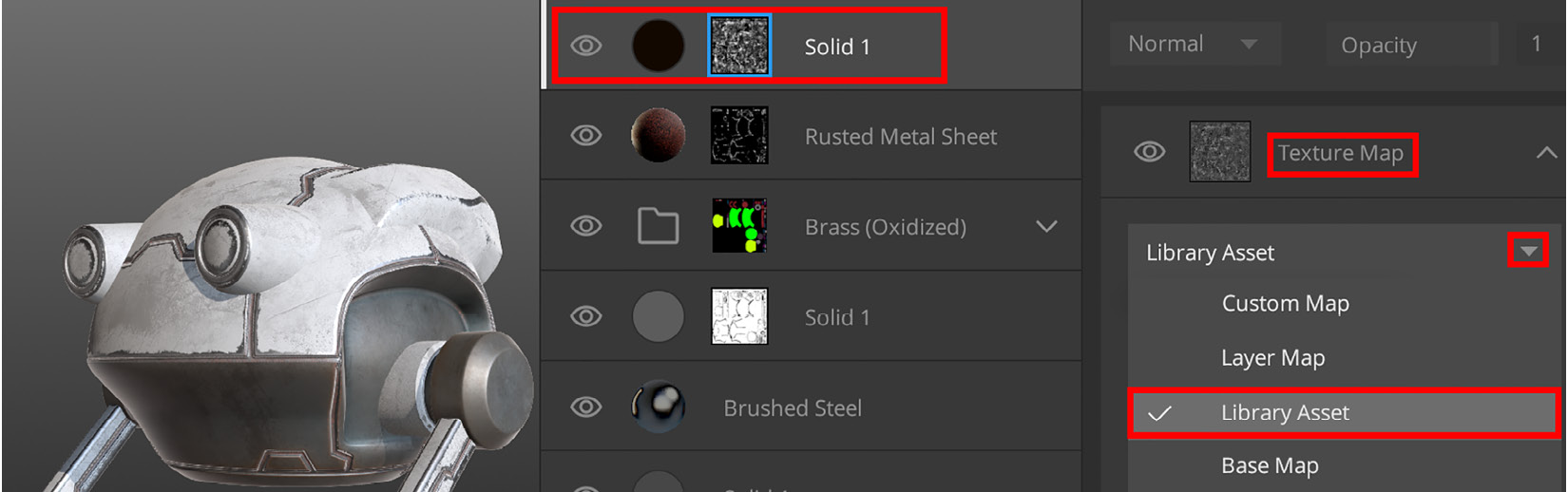
Figure 5.23 – Adding a library asset to the mask
- Click on the Folder icon (highlighted in green in Figure 5.24) to load an asset. A Local Library tab will open up. Set the asset type to Imperfection. Search for and add Scratched Metal.
- Download this Imperfection material and click on its icon. This Imperfection material will be used inside the mask, and its effect is to break up the dirt layer, making the dirt look more realistic, as illustrated in the following screenshot:
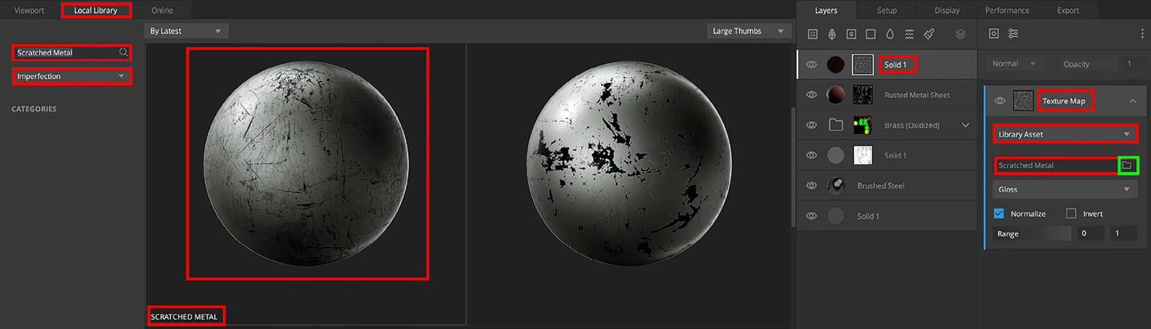
Figure 5.24 – Adding the Scratched Metal imperfection material to the layer mask
- Click on the Add Mask Modifier icon and add a Brightness/Contrast modifier to the selected mask.
- In the Property stack, find the Brightness/Contrast menu and set Brightness to 0.5 and Contrast to 3.42. This will make the dirt more noticeable on the model.
- Let's add some fine scratches to the model. Click on the Add Surface Layer icon, then in the Online surface library, search for Scratched Painted Iron. Download this surface material and click on its icon.
This applied the Scratched Painted Iron surface material (with fine scratches) all over the model. At this time, this surface is still covering the entire model, but we will fix this soon, as seen in Figure 5.25.
- Change the ALBEDO setting as follows: Red: 30, Green: 30, and Blue: 30. Change the ROUGHNESS setting as follows: Red: 106, Green: 106, and Blue: 106. The ALBEDO and ROUGHNESS settings are shown in the following screenshot:
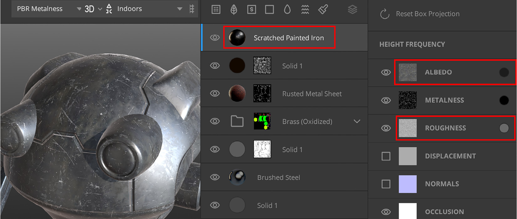
Figure 5.25 – Adding a Scratched Painted Iron surface to the model and changing its ALBEDO and ROUGHNESS settings
- Press the K shortcut key to add a mask stack to this layer, and then click on the mask.
- With the mask selected, in the Property stack, click on the Add Mask Component icon, and then choose Texture Map.
- In the Texture Map menu, change Custom Map to Library Asset in the drop-down menu (as you did earlier in Step 13).
- Click on the Folder icon to load an asset from the library. Switch to the Online library tab. Set the type to Imperfection, and search for Scratched Painted Metal.
- Still in the same Texture Map menu of the Mask component, set Range to 0.85.
- Click on the Add Mask Modifier icon and add a Brightness/Contrast modifier.
- In the Brightness/Contrast menu, set Brightness to -1 and Contrast to 3. This changes the effect of the Scratched Painted Iron surface to look like fine scratches in the white paint, as can be seen in Figure 5.26.
- Now, for the last step, we will texture the camera eyes of the Robot Drone. Click on the Add Solid Layer icon. Set ALBEDO as follows: Red: 0, Green: 34, and Blue: 255. This has added a bright blue color layer over your entire model.
- Change Metalness to Pure White color and change Roughness to Pure Black color. This changed the blue layer, to look like a blue metallic-looking material. At this time, this Solid layer is covering the entire model, but we will fix this soon.
- Select the Solid Layer (the blue one you just created). Click on the Add Material ID on this Layer icon. This creates a material ID mask in your blue metallic layer.
- Now, we will pick the material ID color of the camera eyes. Press Q + left-click on Camera Lens inside the Viewport (the bright blue material ID color). Your blue metallic color will now be limited to the camera eyes, as seen in Figure 5.26.
Congratulations! You've just completed your first procedural-texturing tutorial! Your model should now resemble the model shown here:
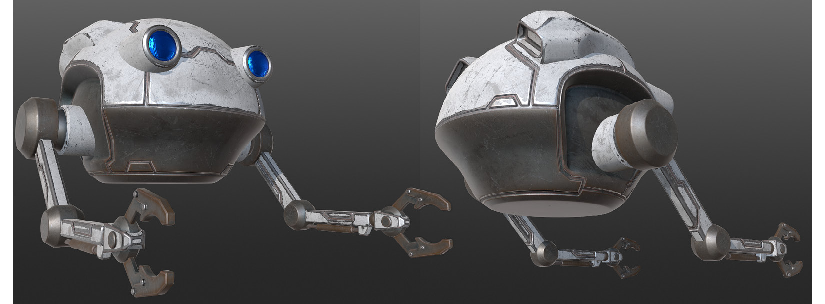
Figure 5.26 – The procedural textures are now done for the Robot Drone model
In this section, you learned a procedural-texturing workflow for mechanical types of models, by using features such as masking to create edge wear and to add dirt inside grooves.
You learned to apply surfaces, solid layers, and smart materials, and now know how to apply these to specific areas of your model by using the material ID mask feature.
In the next section, we will use procedural-texturing methods to texture the Alien Plant. This workflow will be slightly different since it is an organic-shaped model.
Texturing the Alien Plant in Mixer
In the previous section, you learned how to use procedural-texturing methods to texture the Robot Drone by following the step-by-step tutorial. This experience is invaluable since you've learned so many things while going through the steps to get to complete the Robot Drone's textures (the end result can be seen in the model in Figure 5.26).
But for this section, you will do something completely different. Now, you have free rein to experiment with procedural texturing on the (provided) Alien Plant model. You can apply any smart material or surface texture and use any setting that you choose. This section will provide you with a chance to put your newfound knowledge of procedural texturing to good use.
As previously mentioned, if you prefer to follow along with another step-by-step tutorial, I've created this tutorial: Additional Content Volume 4 - Step-by-Step Texturing of the Alien-Plant.pdf. A link to this is provided in the Further reading section.
Let's get started with the texturing of the Alien Plant, as follows:
- Download the AlienPlant.fbx model from the online repository here: https://github.com/PacktPublishing/Unreal-Engine-5-Character-Creation-Animation-and-Cinematics/tree/main/Chapter05.
- Download the following five texture files: AlienPlant_Normals.tga, AlienPlant_AO.tga, AlienPlant_Curvature.tga, AlienPlant_Material_ID.png, and AlienPlant_Cavity.tga from the online repository at https://github.com/PacktPublishing/Unreal-Engine-5-Character-Creation-Animation-and-Cinematics/tree/main/Chapter05.
- Load the Alien Plant model into Mixer in the same way that you used to load the Robot Drone model.
- Assign the Alien Plant's Normals, AO, Curvature, and Material ID Base Maps (in the same way that you did for the Robot Drone model).
- Your Alien Plant model is now ready for your procedural-texture experimentation.
- Go ahead and texture the Alien Plant model in any way that you want to. When you've finished this task, return to this point in the chapter.
Let's take a look at the way I have procedurally textured my own Alien Plant model. My model is shown in Figure 5.27.
Note
Your Alien Plant model will look completely different than mine if you've been experimenting with procedural textures as was suggested for this section. Remember: there is no right or wrong end result for this section. The important part of this lesson is to learn by experimentation and to have fun doing so!
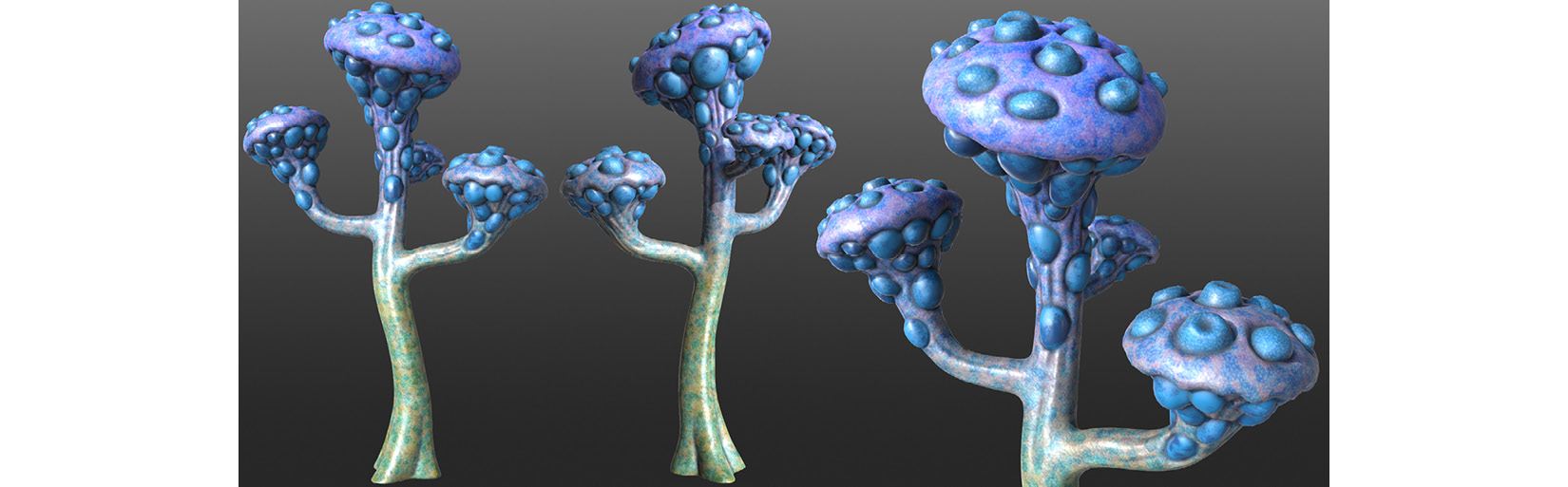
Figure 5.27 – My completed Alien Plant model
In this section, you learned how to experiment with procedural-texturing methods to texture the Alien Plant model.
In the next section, I will show you how to export your textures for use in UE5.
Exporting your materials for use in UE
So, you have completed both procedural-texturing tutorials and you have some great-looking materials made up of multiple layers.
But you might be wondering how to use these materials in UE5. This is actually a very simple step, so let's dive right in, as follows:
- Click on the Export tab shown by the number 3 in Figure 5.2.
- In the Export Target menu, next to Export Location, choose a folder on your hard drive.
- Next to Asset Name, type a name for your file.
- Next to Texture Preset, select Metalness Maps as the type. For the texture maps to export, check the checkboxes that are shown in the following screenshot:
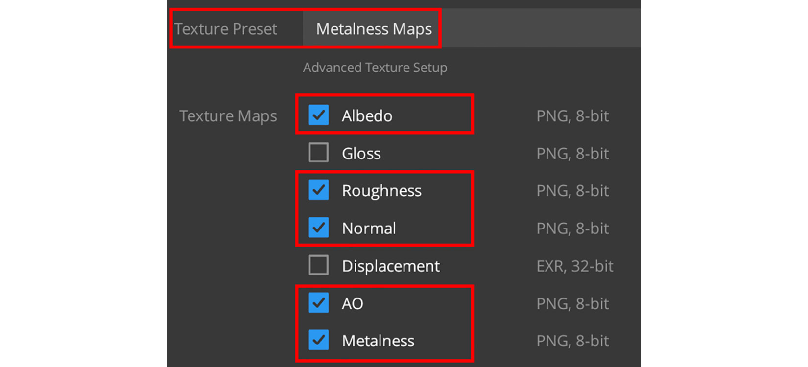
Figure 5.28 – Selecting texture maps to export for UE5
You've just learned how to export materials from Quixel Mixer. In Chapter 7, Setting up Materials in UE5, I will show you how to use these texture maps to create materials in UE5.
This concludes all of this chapter's tutorials!
Summary
You have successfully completed two procedural-texturing tutorials, and in the process of doing so, you've learned a great deal about different procedural-texturing workflows. In this case, you learned the difference between texturing mechanical-shaped and organic-shaped models.
You should now be able to procedurally texture your own 3D assets for your 3D movies.
Your 3D movie's Robot Drone and Alien Plant 3D assets are now 100% complete and ready to be exported to UE5. In the next chapter, we will move our focus to the basics of UE5: the UI, basic menus, and navigation controls.
See you in the next chapter!
Further reading
I have created three additional tutorials for this chapter, as follows:
- Additional Content Volume 2 - Creating Material ID Maps.pdf
- Additional Content Volume 3 - Painting Lines in Blender.pdf
- Additional Content Volume 4 - Step-by-Step Texturing of the Alien-Plant.pdf
You can download these three files from the online repository here: