
Chapter 4: UV Maps and Texture Baking
In the practical tutorials of Chapter 2, Having Fun with Modeling a Robot Drone Character, and Chapter 3, Let's Sculpt an Alien Plant!, you created a Robot Drone model and an Alien Plant model.
So far, these gray (untextured) models look great. Unfortunately, having these plain gray models on your virtual 3D movie set would not look that realistic, would it?
In order to make them look more real, first, we need to prepare the models so that they are able to receive textures and materials.
We will start by exploring some key concepts regarding textures and materials. Then, we will move on to learn about the concept of UV mapping.
After this, we will prepare our Alien Plants' shading and then go through the step-by-step process of UV mapping the model. We will do the same process for the Robot Drone model, but with some variations to our method since it is a mechanical model made up of multiple parts.
Once both Alien Plant and Robot Drone are UV mapped, we will briefly explore a free texture map baking software, called xNormal. Then, we will go through the entire process of baking texture maps with xNormal, for both our Alien Plant and Robot Drone models.
Finally, at the end of this chapter, both of your models will be UV mapped and have texture maps baked. They will be ready for the final texturing stages in Blender and Quixel Mixer.
At the end of these lessons, you will have a solid understanding of the whole texturing process: model preparation, UV mapping, and texture map baking.
For those who wish to skip this chapter's practical tutorials, the UV mapped Alien Plant model, AlienPlant_UV_Mapped.blend, and the UV mapped Robot Drone model, RobotDrone_UV_Mapped.blend, along with all of their baked texture maps are all available to download from the online repository at https://github.com/PacktPublishing/Unreal-Engine-5-Character-Creation-Animation-and-Cinematics/tree/main/Chapter04.
In this chapter, we're going to cover the following main topics:
- Exploring the basic concept of textures and materials
- Understanding the basic concept of UV mapping and why it is needed
- Fixing shading issues on meshes
- UV mapping models in Blender
- Understanding the concept of texture baking and why it is needed
- Baking textures using xNormal
First, we will explore the core concepts of textures and materials.
Technical requirements
You will need the following hardware and software to complete this chapter:
- A computer that can run basic 3D animation software.
- You will need to install Blender from https://www.blender.org/download/.
The Blender version used in this chapter is version 2.93.5. Even if your version of Blender is newer, the examples should still work without any problems.
- You will need to install the latest version of xNormal from https://xNormal.net/.
The files related to this chapter are placed at https://github.com/PacktPublishing/Unreal-Engine-5-Character-Creation-Animation-and-Cinematics/tree/main/Chapter04
What are textures and materials?
In this section, we will explore the core concepts of textures and materials. First, let's start with the concept of textures.
Textures
In 3D computer graphics, we use something called a Texture (or a texture map) to describe an aspect of the mesh surface's appearance.
Usually, textures (or texture maps) are made from raster images (pixels in a grid format), or the textures can be procedurally generated (this is also known as Procedural Texturing).
Note
Procedural texturing is a 3D texturing method whereby textures and materials are generated by an algorithm inside 3D software (such as xNormal, Quixel Mixer, or Substance Painter). The algorithm uses information from your texture maps and/or 3D mesh, combined with settings that you have control over to create procedural textures. We will explain procedural texturing, in more detail, in Chapter 5, Texturing Your Models in Quixel Mixer.
Here is a brief description of the types of texture maps that we will use for our tutorials:
- Albedo Map: This is the color of the surface without specular highlights or shadows. In some software, such as Unreal Engine and Blender, an albedo map is also referred to as a base color map.
- Metalness Map: This indicates which parts of a surface are made of metal and which parts are not. In the real world, a surface can either be metallic or non-metallic. However, because we want the creative freedom to create materials that do not need to be physically possible, we can choose a metalness value range of between 0 and 255.
- Roughness Map: This refers to how rough or smooth a surface is, represented as a grayscale (black to white) tonal value between 0 and 255 (where 0 = 100% smooth and 255 = 100% rough).
- Normal Map: These texture maps are used to give the illusion of height and depth in a material. They work by manipulating the way that light interacts with the surface of the material to fake small bumps and indentations.
- Ambient Occlusion Map (also known as the AO Map): This is a grayscale texture map that is used to create soft shadowing without a direct light source (indirect lighting), such as on an overcast day. Cracks, dents, and crevasses would receive less lighting, so these areas would get more shadows.
- Emissive Color Map: This is sometimes called a Self-Illumination Map, and it is used to create glowing areas on your mesh's surface. For example, you can use this kind of map to create interesting light effects in your material.
- Displacement Map: This is used to deform (displace) a mesh based on the grayscale value of the displacement texture, whereby the black areas will create deep crevices and the white areas will create peaks. In Unreal Engine, the displacement texture map works by utilizing a feature called Tessellation, which subdivides the mesh to give you more geometric detail to use during the displacement process.
- Curvature Map: This is a texture map that gives a grayscale value to sharp edges and cavities in your mesh. This information is used for procedural texturing.
- Material ID Map: This kind of texture map is used to assign a color value to parts of your model so that you can use that color information during procedural texturing.
Now that you understand the different types of texture maps, let's explore what materials are.
Materials
Materials are made up of one or more texture maps. Materials use these texture maps to describe the various physical aspects of a surface's appearance.
Materials can also be procedurally generated in software such as Quixel Mixer or Substance Painter.
Here is an example of how texture maps could be used inside a hypothetical rock material:
- The albedo map will describe the color of the rock material.
- The normal map will describe how bumpy the rock material should be.
- The roughness map will describe how smooth or rough the surface of the rock material is.
- The AO map describes the self-shadowed areas in the rock material.
- The rock material contains no lights or metal parts, so we do not need an emissive color map or a metalness map for the rock material.
In this section, you learned about the basic concept of textures, procedural texturing, and materials. This knowledge is an essential stepping stone for learning more about texturing as one of the main disciplines in 3D computer graphics.
In the next section, I will explain the basic concept of UV mapping and why it's needed.
Understanding UV maps
UV maps represent a 3D model's surface as a 2D representation, as shown in Figure 4.1.
Imagine a geographical map of the Earth; the map is 2D, but we all know that it is a flattened representation of the surface of our planet and that the map wraps around the spherical (globe) shape. Similarly, a 2D UV map represents a 3D surface.
You can download an example of an Earth Globe model (Earth.blend) at https://github.com/PacktPublishing/Unreal-Engine-5-Character-Creation-Animation-and-Cinematics/tree/main/Chapter04.
Open this Blender file and select the model named Earth. Then, click on the UV Editing Workspace tab to examine the UV map of this model.
This will give you a good understanding of the way that UV mapping works. See Figure 4.1 to view what this Earth model looks like in the 3D Viewport window and the UV Editor window:

Figure 4.1 – The Earth model and its UV map inside the UV Editor window (on the left-hand side)
Now that you understand the basic concept of UV mapping, let's do a practical tutorial to learn how to create a UV map.
Note
UV unwrapping describes the process of UV mapping. The term UV (or UVs) also refers to a model's UV map.
UV unwrapping the Alien Plant model
We will start our journey of learning about UV maps by UV unwrapping the Alien Plant model. Before we can start, we need to prepare the mesh's shading. In the next section, we will do just that.
Fixing shading issues
Import the Alien Plant model from the directory that you used when you completed the Using Instant Meshes for Auto-Retopology section of Chapter 3, Let's Sculpt an Alien Plant!.
Note
Low-poly describes a low-resolution mesh (that is, low geometric detail). Similarly, the term high-poly describes a high-resolution mesh (that is, dense geometric detail).
Open the low-poly Alien Plant model in Blender and switch to Edit Mode with Edge Selection mode turned on. You will notice that parts of the mesh's edges are displayed in a turquoise color. This is because we've imported the model as a .obj file from Instant Meshes, and some edges are set to display as sharp. Fortunately, there is a very easy way to fix this:
- Select all of your edges on the model and then right-click inside the 3D Viewport.
- In the menu that pops up, select Clear Sharp. The edges will now turn back to how they normally appear.
- Switch back to Object Mode. Select the model and right-click anywhere inside the 3D Viewport.
- Select Shade Smooth from the menu.
So, you've just learned how to fix a shading issue caused by importing a model with edges that were set to display as sharp.
In the next section, I will show you how to place UV seams in your Alien Plant model.
Handy Tip
A quick way to select an edge loop (in Edge Selection mode) is to hold the Alt key while selecting an edge that is part of the edge loop. A quick way to select a range of edges (shortest path) in edge selection mode is to select the starting edge and then move your mouse pointer to the end of the range; then, hold Ctrl and left-click to complete the selection.
Creating UV seams
The first step of UV unwrapping the model is to place UV seams. These UV seams are a visual representation of the edges of the texture.
Take the analogy of the map of Earth. In order to flatten the Earth's shape (with no overlapping parts), it needs to be cut somewhere. These cuts are similar to UV seams.
So, now that you have a grasp of UV seams, let's create some UV seams on our Alien Plant model.
Let's start by setting UV seams on the biggest head of the Alien Plant model:
- First, select an edge loop, as shown in Figure 4.2:
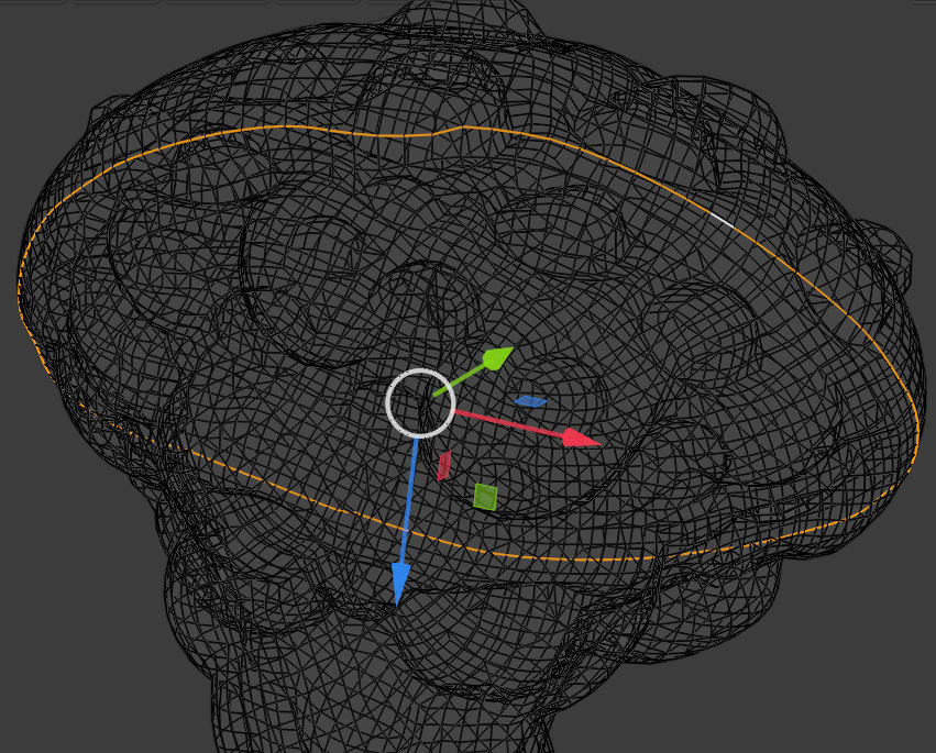
Figure 4.2 – Selecting the edges
- If you find that your edge loops are not connecting up correctly, you can do mesh editing on some of the edges by switching to Vertex Selection mode and then pressing J to use the Connect Vertex Path tool.
- Connect some of the vertices around the bases of the stems to smooth out the edge loops and make them more rounded.
- With the edge loop still selected, right-click inside the Viewport and select Mark Seam from the menu. Alternatively, you can use the U shortcut to open the UV mapping menu and then choose Mark Seam from that menu:

Figure 4.3 – Marking the seam
- These selected edges will now turn red to indicate that it is a UV seam (where the edge of the UV map is), as shown in Figure 4.4:

Figure 4.4 – The edges are now red
- Continue to set UV seams for all four of the Alien Plant model heads. Use Figure 4.5 as a guide for the creation of the remaining UV seams of the Alien Plant model. Additionally, you can load the provided Alien Plant model as an example of the UV seam placement.
If you haven't done so already, download the completed UV mapped Alien Plant model, AlienPlant_UV_Mapped.blend, from the online repository at https://github.com/PacktPublishing/Unreal-Engine-5-Character-Creation-Animation-and-Cinematics/tree/main/Chapter04.
Load this model into Blender to study the way that we have set the UV seams on the model. Switch to Edit Mode in the modeling workspace so that the UV seams become visible. Then, create your UV seams in the same way. The completed UV seams on the Alien Plant model can be seen in Figure 4.5:
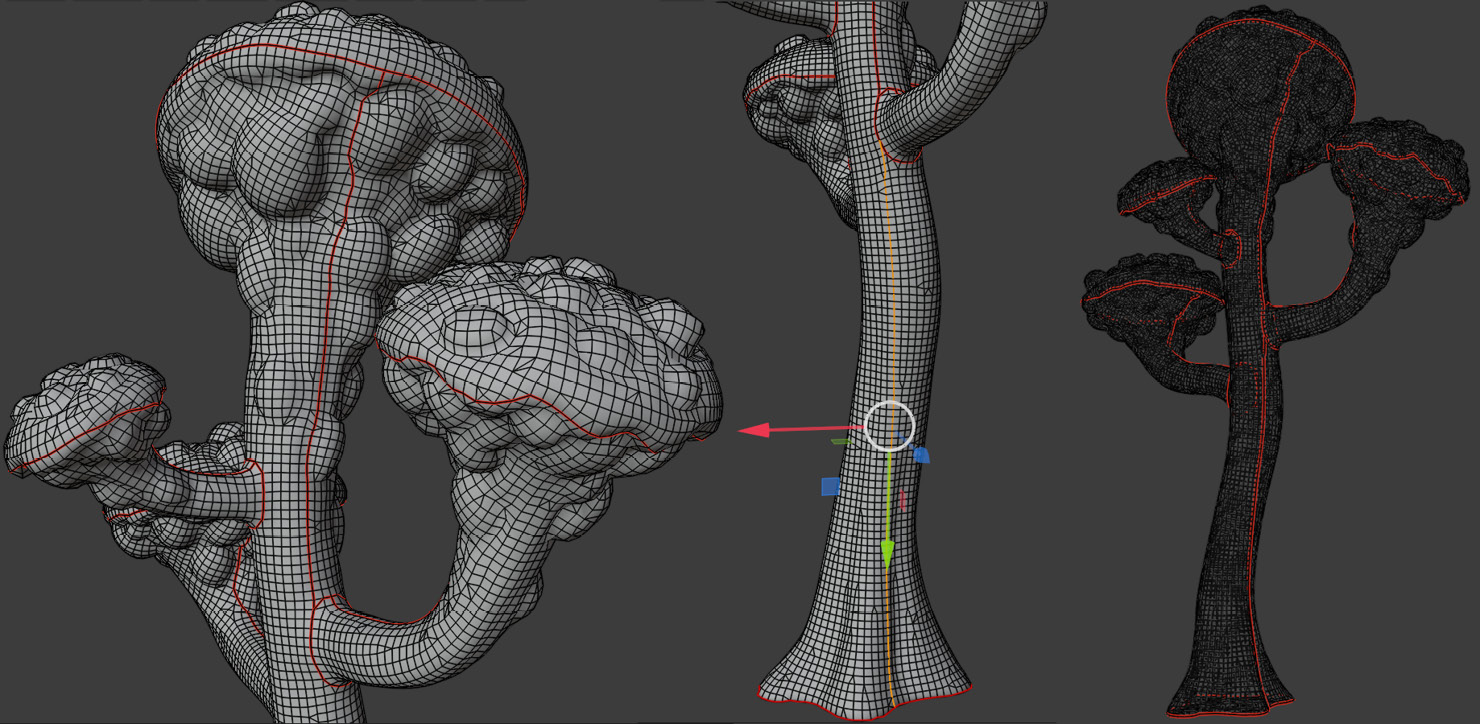
Figure 4.5 – The completed UV seams on the Alien Plant model
So, you've just learned how to set UV seams on a model. In the next section, we will learn how to do UV unwrapping.
UV unwrapping the Alien Plant model
Now, we will start on the UV unwrapping stage of the Alien Plant model. Perform the following steps:
- Select the Alien Plant model; then, select the UV Editing Workspace tab from the Topbar.
- Make sure your model is in Edit Mode, then enable face selection mode. Press A to select all the model's faces.
- Press U for the UV mapping menu and, from there, select Unwrap.
- The model will now be UV unwrapped, and you can see the result in the UV Editor window (the window on the left-hand side panel of your 3D Viewport).
- In the UV Editor window's header bar, click on the small arrow next to the Show Overlays icon. Then, in the drop-down menu, use the settings shown in Figure 4.6:

Figure 4.6 – The Show Overlays menu settings in the UV Editor window
Enabling Stretching and setting the Stretching type to Area (in the Show Overlays menu) helps you visualize any stretching of your UV map by using colors.
The Blue and Green colors mean the UVs are optimal (that is, not stretched). The Red and Yellow-colored areas mean there is stretching (or the UVs have too much texture space allocated).
- With your model selected, switch to Edit Mode and then enable face selection mode. Press A to select all the model's faces.
- In the UV Editor window, use the Select Box selection mode to drag select all the faces on the model. Then, open the UV drop-down menu in the UV Editor window's header bar.
- Inside this UV drop-down menu, select Minimize Stretch to improve your UVs.
The minimize stretch function works best on organic-shaped meshes. It is best not to use the minimize stretch function on mechanical-shaped meshes (such as your Robot Drone model). The reason for this is that the algorithm that Blender uses for minimizing (UV) stretching works better on organic-shaped meshes. On mechanical-shaped meshes, it can sometimes cause unwanted distortions in your UV map.
Move and rotate the separate UV parts that you can see in Figure 4.7 (these UV parts are called UV islands in UV mapping terminology) so that the UV islands can fit better into the square. If you want to scale them, make sure you scale all of the UV islands together and only use uniform scale; otherwise; your UVs won't have an even distribution of texture space.
- Rotate the UV islands of the Alien Plant model so that they are facing the same way as the model and leave a bit of space between the UV islands, as shown in Figure 4.7:
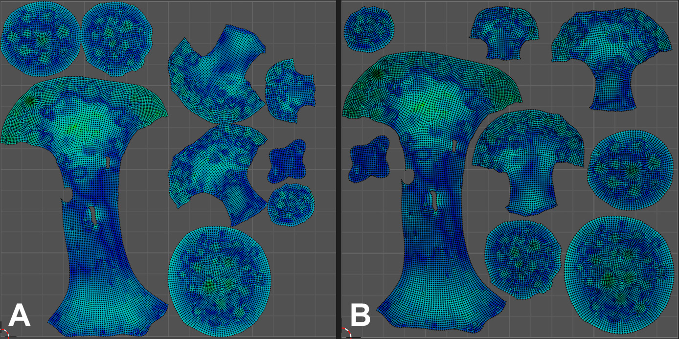
Figure 4.7 – (A) The original UV layout and (B) the modified UV layout with parts rotated to face the same direction
The UV mapping stage of the Alien Plant model is now complete. You have just learned how to UV map a model in Blender.
In the next section, we will prepare the Alien Plant model for exporting by triangulating its mesh.
Triangulating the Alien Plant model
At this point, your model is mostly made up of four-sided faces (also known as Quads). However, to bake the textures (and for use in Unreal Engine), we need the model to be made up of triangles (that is, triangular faces; also known as Tris).
Select all the faces in the model and then press Ctrl + T to triangulate the mesh. Save the model with the triangular faces in Blender's (.blend) file format.
You just learned how to triangulate a mesh for use in texture baking and Unreal Engine.
In the next section, I will show you how to export the Alien Plant model from Blender in .fbx file format.
Exporting the Alien Plant mesh
Now, let's take a look at the settings we will use to export the Alien Plant model from Blender in .fbx file format.
Important
You will use the same settings as any other model that you want to export from Blender in the .fbx file format.
Perform the following steps:
- Select your model in Object Mode inside Blender.
- Navigate to File | Export | FBX (.fbx). The Blender file view window will open. Use the following settings in this window:
- In the Include drop-down menu, check the Limit to Selected Objects checkbox.
- In the Transform drop-down menu, set Forward to -Y Forward. Set Up to Z Up.
- In the Geometry drop-down menu, set Smoothing to Face.
- In the Geometry drop-down menu, check the Tangent Space checkbox.
- In the file's Name entry box, choose a suitable file name for the exported file.
- Click on the Export FBX button.
See Figure 4.8 for all of the preceding export settings:

Figure 4.8 – The Blender file view window to export models
You have just learned how to export models in .fbx file format.
We will use this version of the Alien Plant model that you've just exported in .fbx format as the low-poly version of your Alien Plant model for use in xNormal for texture baking purposes in the Baking texture maps section. Later, we will also use this model inside UE5.
In the next section, I will show you how to create the UV maps for the Robot Drone model.
Handy Tip
To hide and unhide items or mesh components, use the following shortcuts: press H to hide the selected item or components. Press Shift + H to hide unselected items or components, and press Alt + H to unhide all items or mesh components.
UV unwrapping the Robot Drone model
In this section, you will UV unwrap each part of your Robot Drone model individually. Then, you will combine the unwrapped UV maps into a single UV map later.
We will start the lesson by loading the Robot Drone model that you created in the practical tutorial of Chapter 2, Modeling a Robot Drone Character. Perform the following steps:
- Save a backup copy of the Robot Drone model that you created.
- Delete the right-hand side of your Robot Drone's mesh parts, except for the body, as shown in Figure 4.9.
- Separate all the parts of the low-poly model into individual objects. To do this, select all the faces of mesh parts that you have joined before. Press P to separate the model parts and choose the By Loose parts. Each new separated object part will also be listed in the outliner panel.
- Use the Hide, Unhide, and Hide Unselected shortcuts to isolate model parts while you set your UV seams. By isolating model parts while setting UV seams, it is easier to focus on a specific model part.
- Now create UV seams for all the Robot Drone parts. Use Figure 4.9 as a guide to show you where to place your UV seams for the Robot Drones' model parts. You can also load my Robot Drone model to use as a guide for the UV seam placement.
If you haven't done so already, download the completed UV mapped Robot Drone model, RobotDrone_UV_Mapped.fbx, from the online repository at https://github.com/PacktPublishing/Unreal-Engine-5-Character-Creation-Animation-and-Cinematics/tree/main/Chapter04.
- Load this model into Blender to study the way that we have set the UV seams on the model. Switch to Edit Mode in the modeling workspace so that the UV seams become visible. Create the UV seams on your Robot Drone model in the same way as I did on mine:

Figure 4.9 – The Robot Drone's UV seams (as indicated by the red lines)
- Select one of the model parts of the Robot Drone model. Then, select the UV Editing Workspace tab from the Topbar.
- Make sure your model part is in Edit Mode. Then, enable Face selection mode. Press A to select all the model part's faces.
- Press U for the UV mapping menu and select Unwrap. This model part is now UV mapped.
- Repeat this UV mapping process for the rest of Robot Drone's model parts.
Note
There should not be any significant amount of stretching in your UV map if you place your UV seams in the same way as I did on my Robot Drone model.
- Once all your Robot Drone's model parts have been UV mapped, select all of the faces of all the model parts.
- In the Topbar of the UV Editor window, select UV | Average Islands Scale. This will scale each model part's UV map to have the right proportions compared to the other model parts.
- From the same UV menu, select Pack Islands to pack all the UVs into the square (with no overlapping UV parts). In Part A of Figure 4.10, you can see Pack Islands highlighted in the menu.
- A minimized Operator panel will appear. Open the Pack Islands menu and set Margin to 0.015. This will move the UV Islands to have a bit of space between them. This is called Edge Padding in UV mapping terminology, as shown in Part B of Figure 4.10:

Figure 4.10 – (A) Selecting the pack islands function and (B) adjusting the margins between the packed UV islands
- Save the model in Blender's (.blend) file format. Later in this chapter, we will return to using this saved version of the Robot Drone model.
Your UV map is now complete! The Robot Drone model should have a single UV map laid out inside the square, and this UV map contains all the individual parts of the model, as shown in Figure 4.11:

Figure 4.11 – The completed UV map for the Robot Drone model
Note
Your UV map will differ in layout from mine, but the UV islands will be similar in shape if you placed your UV seams in the same place as I did.
In this section, you learned how to do UV unwrapping for mechanical-shaped models. This will come in very useful for your own future projects.
Now that you've UV mapped both the Alien Plant and the Robot Drone models, you are ready to move on to the texture baking stage of this chapter, which we will discuss, in detail, next.
Understanding texture baking
Texture baking is a process by which the xNormal software (I will cover xNormal in the Introduction to xNormal section) takes certain aspects from the surface of the high-poly model and then projects those aspects onto the surface of the low-poly model, to create new texture maps. These new texture maps can be used in procedural texturing software, such as Quixel Mixer.
Note
We will cover the use of Quixel Mixer in Chapter 5, Texturing Your Models inside Quixel Mixer.
The end result of the texture baking process is a texture map that holds information about various aspects of the high-poly model. For example, some of these aspects include the degree of sharpness of the edges of the model or information about fine geometric details on the high-poly model.
In xNormal, we can choose which aspects from the high-poly model we want to bake into a texture map. For our tutorial, we will bake three of these texture maps. The three texture maps that we will bake are listed as follows:
- The normal map
- The AO map
- The curvature map
Important
In Quixel Mixer, the texture maps that we will bake in xNormal are referred to as base maps. Quixel Mixer uses these base maps to generate procedural textures and materials that we will use in Unreal Engine later on.
In this section, you learned about the concept of texture baking and why we need it for procedural texturing.
In the next section, I will introduce the software called xNormal, which we will use for texture baking later.
Introduction to xNormal
xNormal is a free, standalone 3D software that is very popular for baking texture maps.
The reason we're baking texture maps in xNormal is that the process of baking curvature maps in Blender is far too complex for the scope of this book, whereas xNormal is extremely quick and easy to use.
You now know what xNormal is used for. In the next section, we will learn how to prepare the Robot Drone model for use in xNormal.
Preparing the Robot Drone model for xNormal
Now, we need to export the Robot Drone model's high-poly and low-poly meshes so that we can bake the textures in xNormal.
There are two versions of the model to be baked: the low-poly mesh and the high-poly mesh.
Let's start by preparing the Robot Drone model's low-poly mesh first.
Preparing the low-poly mesh
In the UV unwrapping the Robot Drone model section, you separated all of your model parts. In other words now, the model parts are not attached to other model parts anymore.
We will now start to prepare the Robot Drone model's Low-Poly mesh for xNormal:
- Move all of the separated mesh parts away from each other so that there are small distances between them, as shown in Figure 4.12:

Figure 4.12 – The low-poly version of the Robot Drone's model parts are all moved away from each other and then triangulated
Note
The reason we're moving the mesh parts a distance away from each other is to avoid unwanted texture baking artifacts, which are caused by parts of other nearby meshes that are projected onto your baked mesh. The easiest solution for avoiding these texture baking artifacts is to bake your mesh parts with some distance between them. In texture baking terminology, a mesh with parts that are moved away from each other is referred to as an exploded mesh. You won't have the same problem when texture baking a simple (one-piece) mesh (such as the Alien Plant model), but this method is needed when you want to do texture baking on more complex mechanical model parts.
- Save your Robot Drone file twice using a different filename for each of the two files: RobotDrone_LowPoly and RobotDrone_HighPoly.
- In the RobotDrone_LowPoly file, triangulate all of the mesh parts, as shown in Figure 4.12.
- After the triangulation is complete, select each model part individually. Then, right-click and select Shade Smooth from the menu.
- When all the model parts have both been triangulated and shaded smooth, select all the model parts and export this file as your low-poly version. Do this export by using the .fbx file format in the same way that you exported the Alien Plant model previously.
The Robot Drone's low-poly mesh is now complete. Next, let's move on to prepare the high-poly mesh.
Preparing the high-poly mesh
Now we will start to prepare the Robot Drone's high-poly mesh for xNormal:
- Load your saved RobotDrone_HighPoly file.
- Apply a subdivision surface modifier to each of the following five model parts: Body, Thruster_V2, Eye, Shoulder_Disk, and Elbow_Disk.
- In the Modifier Properties section of the Properties panel, set Levels Viewport to 2. (in Figure 4.13, you can see the five model parts are highlighted in orange. I've also added name tags for easy identification):

Figure 4.13 – The high-poly version of the Robot Drone model's parts
- Now apply the modifier to these five mesh parts.
- After you've applied all of the subdivision surface modifiers, triangulate all the model parts.
- Apply Shade Smooth to the model parts that have the subdivision surface modifier on them but not the low-poly mesh parts.
- When all the model parts are triangulated and a few selected model parts have been shaded smooth, select all the model parts and export them as the high-poly version. Do this export by using the .fbx file format in the same way that you exported previously.
Both the high-poly model and low-poly model export process are now complete. You just learned how to prepare a very complex mechanical model with many parts for texture baking in xNormal.
Now you understand the different workflows that should be used when UV mapping and exporting models to xNormal for organic-shaped models and mechanical-shaped models.
In the next section, you will learn how to use xNormal for texture baking.
Baking texture maps
In the previous section, you prepared and exported the Robot Drone model's high-poly and low-poly versions for texture baking.
In this section, we will start on the texture baking process of the Robot Drone model. Then, afterward, you will use the same method for baking the Alien Plant model.
Open xNormal. You will see a floating window with various menus:

Figure 4.14 – xNormal's UI with the High definition meshes tab currently enabled
We only need a few steps of preparation before we are ready to bake our texture maps. See Figure 4.14 for xNormal's UI:
- Make sure the High definition meshes tab has been selected.
- Right-click anywhere inside the xNormal's window part, as shown in Figure 4.14.
- In the menu that pops up, select Add meshes and select your high-poly model.
- Click on the Low definition meshes tab.
- Right-click anywhere inside the window part of xNormal.
- In the menu that pops up, select Add meshes and select your low-poly model.
- Select the Baking options tab, and then use the settings shown in Figure 4.15:
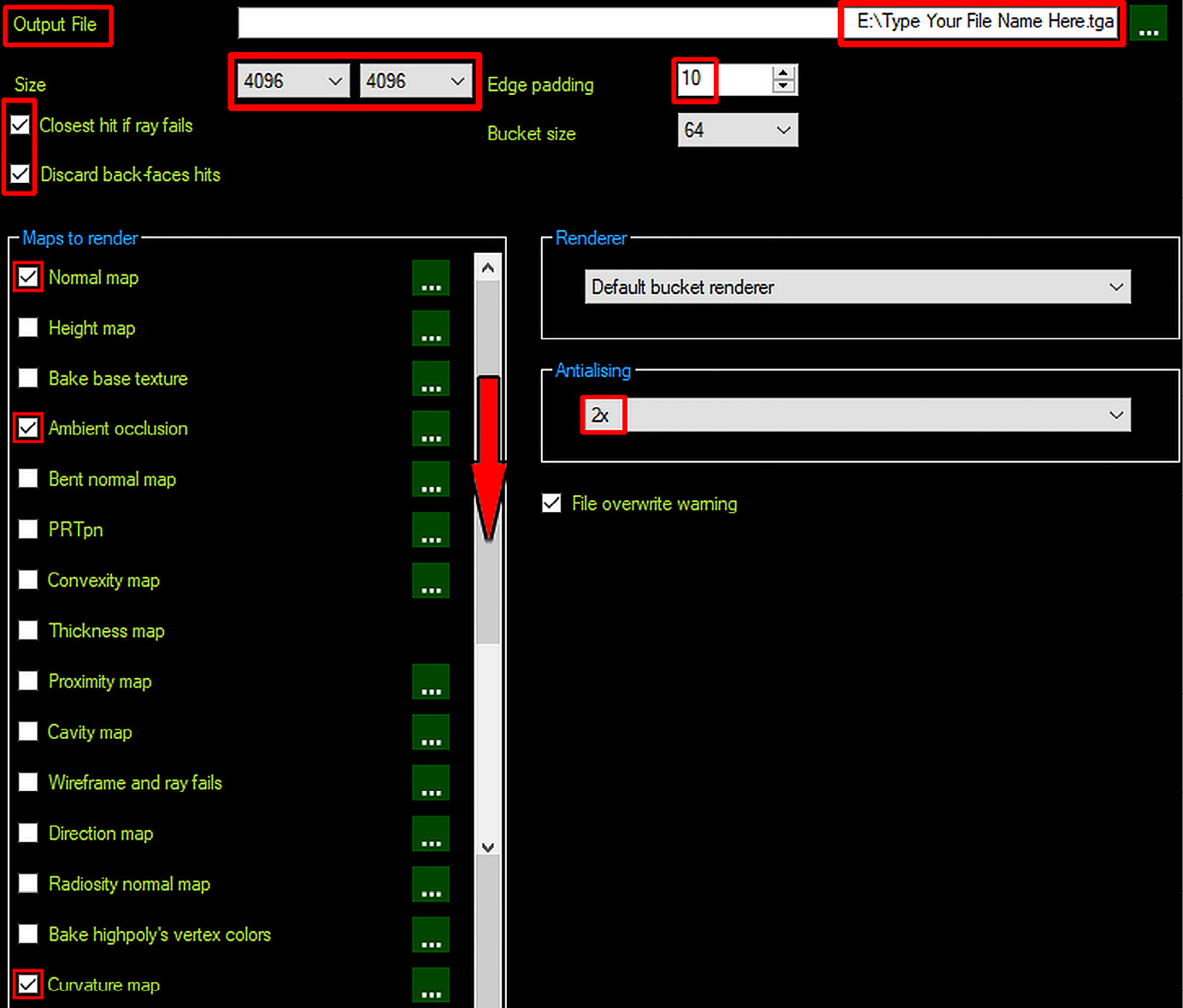
Figure 4.15 – The Baking Options tab's window
- Change your Normal map settings to the settings shown in Figure 4.16. You can do this by clicking on the icon of a green square with three dots inside it, which is next to the name of the map, as shown in Figure 4.15.

Figure 4.16 – Setting your Normal map to use these settings

Figure 4.17 – Setting your AO map to use these settings
- Change your curvature map to the settings shown in Figure 4.18:

Figure 4.18 – Setting your curvature map to use these settings
- Now that you've set up your Render settings for the normal map, the AO map, and the curvature map, go back to the Baking Options tab and click on Generate Maps in the bottom-right corner of the UI, as shown in Figure 4.14.
- xNormal will open another window named Preview, which shows your texture maps as they render. Once the three texture maps are complete, the Close button will change states from grayed out to normal. Click on Close to exit xNormal.
That's it! Your texture maps are now all baked! In Figure 4.19, you can see the six texture maps that I have baked in xNormal for my Alien Plant model and Robot Drone model:

Figure 4.19 – My six baked texture maps (three for each model)
Note
The UV maps' layout for your Alien Plant model and your Robot Drone model will be different than mine. But, it doesn't matter if your UV layout is different than mine since the texture baking process will still work in the same way.
Now you are ready for the procedural texturing tutorial using Quixel Mixer in Chapter 5, Texturing Your Models inside Quixel Mixer.
Summary
ln this chapter, you learned about textures and materials. You understand how to UV map 3D models that are either organic-shaped or mechanical-shaped in form.
You also gained knowledge about how to fix shading issues and triangulate and separate mesh components. Finally, you have learned how to bake texture maps in xNormal.
Going forward from here, in Chapter 5, Texturing Your Models inside Quixel Mixer, our learning journey will take us to the procedural texturing exercises, where we will texture both the Alien Plant and Robot Drone models.