
Chapter 2: Modeling a Robot Drone Character
In the previous chapter, you learned about all the different types of modeling tools in Blender. Now, we will continue our learning journey by jumping right into a practical, step-by-step modeling tutorial in which will create a mechanical Robot Drone character for your sci-fi-themed 3D movie.
We will start off with the very basics by first setting up Blender's Units, then loading reference images (these will act as a guide for your modeling).
Afterward, we will proceed to block out the basic shape of the robot drone's body, before adding details and moving on to the other body parts of the model.
In this chapter, you will gain practical knowledge of 3D modeling by using some of the most powerful modeling functions Blender has to offer, such as creating basic meshes (called primitives), using extrusions, bevels, loop cuts, and insets, creating custom polygonal faces, and much more.
In this chapter, we're going to cover the following main topics:
- Preparing Blender's Units
- Modeling a Robot Drone character
Upon completion of this chapter, you will have both the knowledge and practical experience to start creating your very own 3D assets that you can use in your 3D movie in Unreal Engine 5.
Technical requirements
You will need the following hardware and software to complete this chapter:
- A computer that can run basic 3D animation software.
- A basic understanding of how to navigate and manipulate meshes in Blender. This was covered in Chapter 1, An Introduction to Blender's 3D Modeling and Sculpting Tools.
- You need to install Blender (open source software, or OSS) from https://www.blender.org/download/.
The Blender version used in this chapter is 2.93.4. Even if your version of Blender is newer, the examples should still work without any problems.
The files related to this chapter are placed at https://github.com/PacktPublishing/Unreal-Engine-5-Character-Creation-Animation-and-Cinematics/tree/main/Chapter02
Preparing Blender's Units
Even though we are working with virtual 3D objects in 3D computer graphics, they still need to have an accurate scale (based on the scale/dimensions of real-world objects). This even applies to made-up things, such as the robot drone we will model in this tutorial.
3D software such as Unreal Engine calculates lighting and physics based on the scale of 3D assets. Another reason is that when you are building virtual 3D movie sets, it is a good idea to have a standardized scale for all your 3D assets—this way, it will make it easier to place them because they will have the correct size in relation to other items in the scene.
The scale of the scene and all the assets therein are set by using Blender's Units menu. Let's go through the steps to set up Units, as follows:
- In the Properties panel, find the Scene Properties icon, as highlighted in the following screenshot. Click on this icon to open up the Units drop-down menu. Inside this menu, change Unit System to Metric and Unit Scale to 0.010000, as shown here:

Figure 2.1 – Setting Unit System and Unit Scale
You will notice that the grid in the 3D Viewport now appears larger than before. This setting changes the way Blender navigates and views objects in the 3D view.
- Press N to open the Properties region. Open the View tab on the right-hand border of the 3D Viewport. Inside this menu, you will see another view listed on top of the menu, as seen in the following screenshot. Change Clip Start to 0.01 m and change End to 200 m. Delete the Cube mesh, lights, and camera from your scene so that your default scene will be empty:
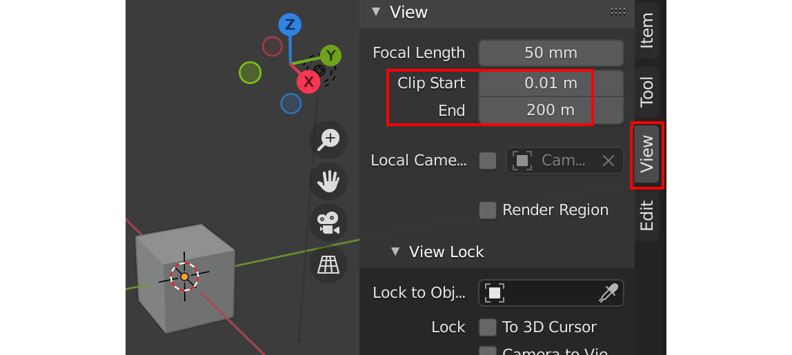
Figure 2.2 – Setting the View settings in the Properties region
- We need to set Blender's Startup File so that Blender automatically uses the correct units, ensuring that every new project will start with the units already set up correctly. In the Topbar, navigate to File | Defaults | Save Startup File, as illustrated in the following screenshot. When you click on this, another menu will pop up and ask you to confirm your choice:

Figure 2.3 – Saving your startup file
All done! You've just set up Blender to use the correct units.
Note
At the time of writing, there was a Unit Scale issue when exporting models from Blender (version 2.93.4) to Unreal Engine 5. This seems to be a problem in the older versions of Blender only, and in some new export tests I've done, it seems to suggest that from Blender version 3.1.2 onward, Unit Scale works if set to 1.0. Regardless, a Unit Scale setting of 0.01 will work in any current version of Blender, so it is still the safest to use.
Now, all your new Blender projects will export 3D assets with the correct scale to other 3D software, such as Quixel Mixer and Unreal Engine.
Handy Tip
Use the following shortcuts for Orthographic views—Front: numpad 1; Back: Ctrl + numpad 1; Right: numpad 3; Left: Ctrl + numpad 3; Top: numpad 7; Bottom: numpad 9.
In the next section, we will load a Blender file that includes reference images for the robot-drone model, and we will get started on the modeling process.
Modeling a Robot Drone character
For those who'd prefer to skip the practical modeling tutorial and go on to Chapter 3, Let's Sculpt an Alien Plant!, the completed Robot Drone model (RobotDrone_Blender_File.blend) is available to download from the online repository here: https://github.com/PacktPublishing/Unreal-Engine-5-Character-Creation-Animation-and-Cinematics/tree/main/Chapter02
In Chapter 1, An Introduction to Blender's 3D Modeling and Sculpting Tools, you learned the theoretical functionality of Blender's modeling tools. Now, you will put all you have learned about 3D modeling into practice!
Let's start with a step-by-step modeling tutorial to create the mechanical body of the robot drone.
Modeling the shape of the body
To get started, we first need to load the Blender file with the reference images already prepared for us.
Download the following RobotDrone_Reference.blend Blender file from the online repository here: https://github.com/PacktPublishing/Unreal-Engine-5-Character-Creation-Animation-and-Cinematics/tree/main/Chapter02.
You will do all your modeling for this tutorial in this Blender file since I have prepared this file to contain all the reference images you will need. The reference images are placed on image planes that are in the scene. Let's take a look by following these steps:
- Open this Blender file and take a look inside the Outliner panel. Here, you will find a folder named REF that contains four reference images that have been prepared for the front, side (using the Right Orthographic view), top, and the mechanical arm (also using the Right Orthographic view). See Figure 2.4 for four reference images as they appear in your Outliner panel when you open the aforementioned Blender file.
- The front, side, and top reference images only appear in Orthographic views and are set to be invisible in the Perspective view. The mechanical-arm reference image has been hidden. The following tip shows you how to toggle the visibility of the mechanical-arm reference image.
Handy Tip
To toggle the visibility of an item by using the Outliner panel, click on the eye icon. For example, in Figure 2.4, Part A, the ARM REF item has a closed-eye icon (see the highlighted icon in the screenshot). In Figure 2.4, Part B, I clicked on this closed-eye icon to turn it into an open-eye icon, which made the item visible (this toggles the item's visibility: closed eye = hidden/open eye= visible).
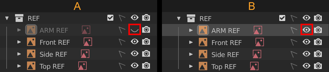
Figure 2.4 – Using the eye icon in the Outliner to toggle visibility
Handy Tip
To toggle the selectability of items by using the Outliner panel, click on the arrow icon, as shown in Figure 2.5. The first option shows the arrow icon in unselectable mode. The second option shows the arrow icon in selectable mode.
Figure 2.5 – Using the arrow icons in the Outliner panel to toggle selectability
In the next section, we will start blocking out the model—in other words, we'll start modeling with the rough approximate shapes.
Block-out shape
All right—we're now ready to get started on the model. Follow the next steps:
- Change your view to Top Orthographic view by pressing the numpad key 7.
- Create a UV Sphere mesh by pressing Shift + A and first selecting Mesh, then selecting UV Sphere from the menu.
- Move, rotate, and scale the UV Sphere mesh to fit the curvature of the robot drone's outer shell that's shown in the reference image. Switch to different Orthographic views as needed. Match the UV Sphere mesh's position to the robot drone in the reference image, as seen in the following screenshot:
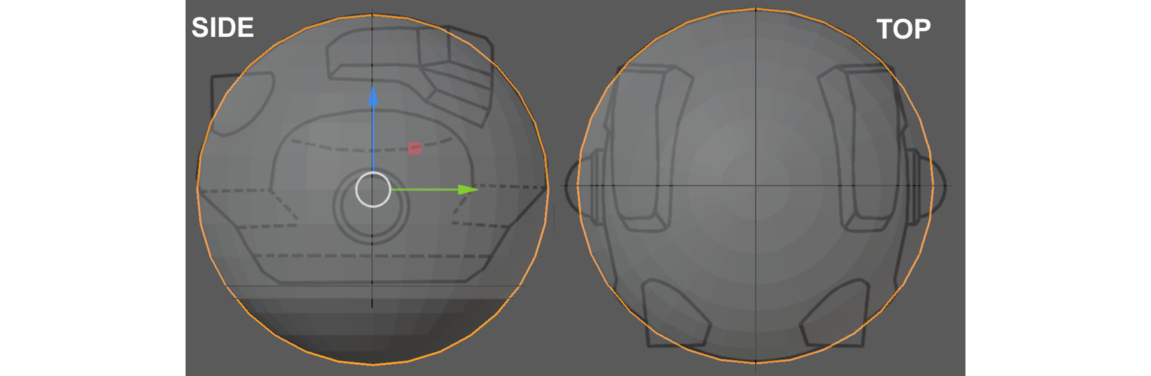
Figure 2.6 – Moving and scaling the Sphere mesh so that it fits the reference image
- Let's delete the lower half of the Sphere mesh. With the Sphere mesh selected, press Alt + Z to turn on X-Ray View Mode. Now, press Tab to go into Edit Mode. Press 3 for Face Select Mode and make sure Select Box in the toolbar is used as the active selection tool (see Figure 1.7 in Chapter 1, An Introduction to Blender's 3D Modeling and Sculpting Tools).
- Press the numpad key 3 to use the Right Orthographic view. Select the lower half of the faces on the sphere, then press Delete on the keyboard and choose Faces from the pop-up menu that opens up. This will delete half of the faces on your sphere. See the following screenshot for how your mesh should look at this stage:
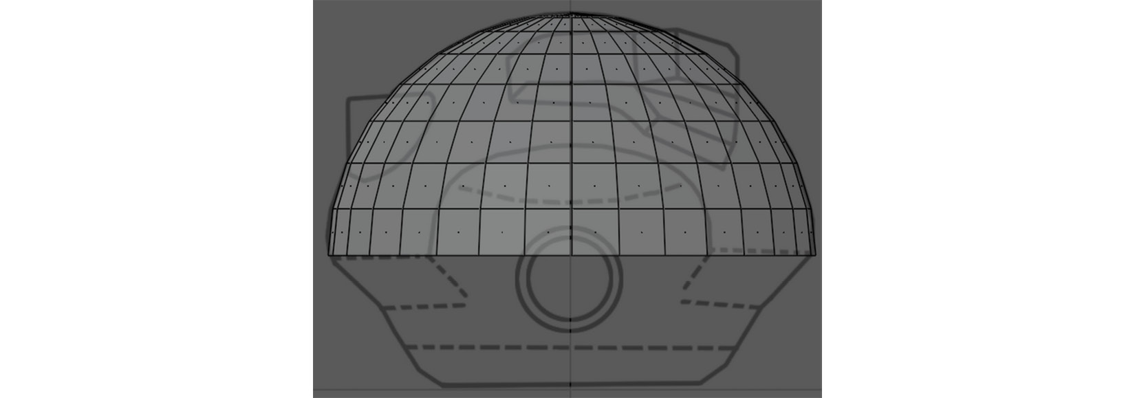
Figure 2.7 – Deleting half of the sphere
- Select the Edge Loop on the bottom of the sphere (where you've just deleted the faces). Press 2 for Edge Select mode, then hold the Alt key and left-click on the edge loop that you want to select.
- With the edge loop still selected, press F to fill the selected edges with a new face. You can leave X-Ray View Mode by pressing Alt + Z again (this toggles it on/off as needed).
- Press 3 for Face Select Mode and then select the newly created face. Press E to extrude the selected face downward to the dotted line, as seen in the reference image in the following screenshot:

Figure 2.8 – Extruding the face downward
- Continue the same process for the rest of the extrusions. Use the Move and Scale modes to modify the extruded faces to fit the silhouette outline of the robot drone, as shown in the following screenshot:
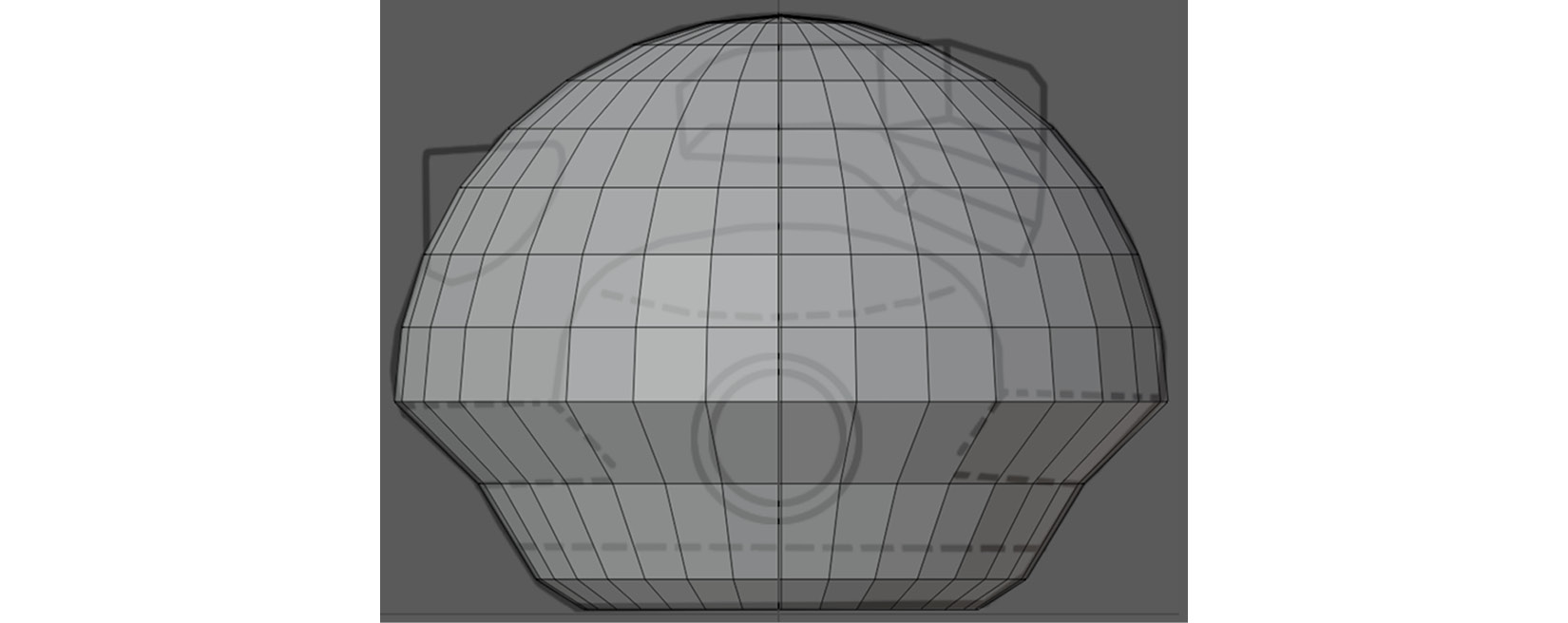
Figure 2.9 – Adding more extrusions and modifying them with Scale and Move manipulation
Handy Tip
Now is a good time to learn how to save your work. Saving your Blender file will allow you to save your progress and then load the file again later. To save, use the Shift + Ctrl + S shortcut. The Blender file View menu will open up. Select a name and a location to save your file. When you want to load this file later, use the Ctrl + O shortcut. The Blender file View menu will open up again. Choose the file you want to load. I advise you to save your work often and also to save different increments of your progress during practical tutorials.
- At the very bottom of the mesh that was created by the face extrusions, select the bottom face. Press the I key to inset the face. Open the minimized Operator panel and change Thickness to 0.025 m.
- Use the Loop Cut tool to add edge loops, indicated by orange lines in the following screenshot:
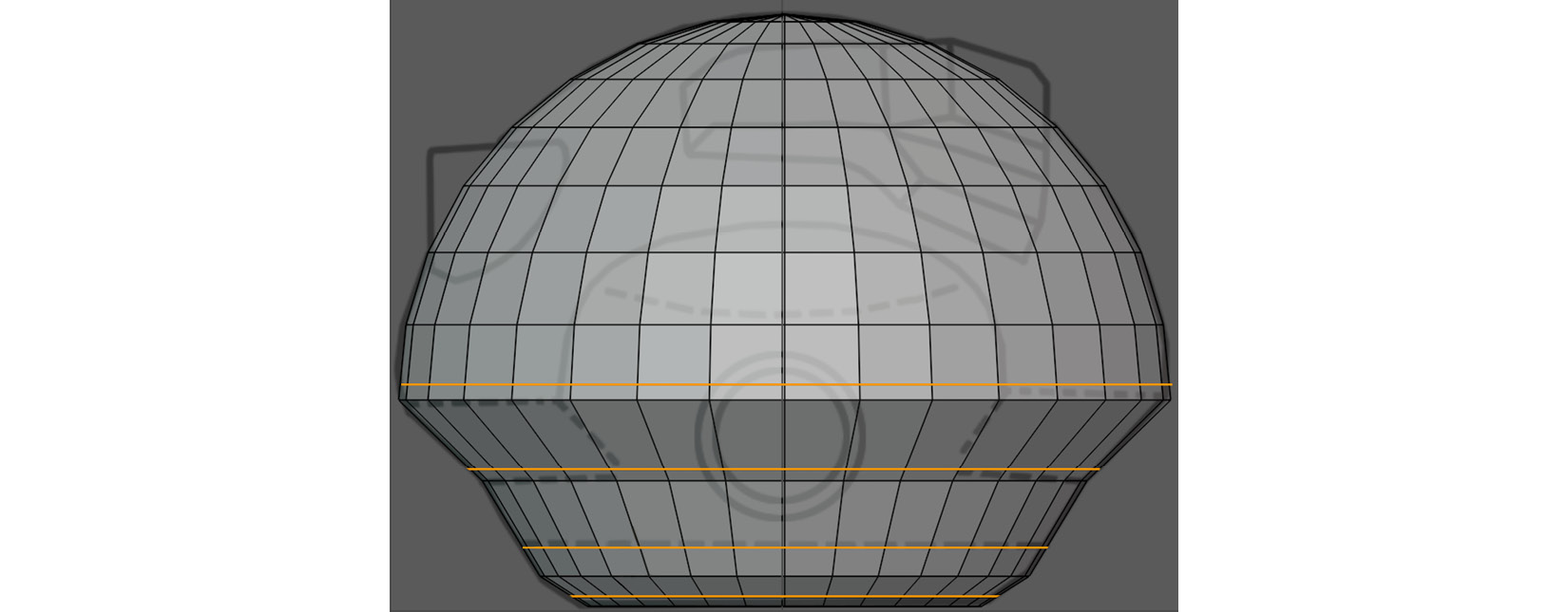
Figure 2.10 – Adding loop cuts
- Press the numpad key 3 to change the view to the Right Orthographic view. Make sure X-Ray View Mode is turned off so that we only do the next step on one half of the mesh. We want to change the flow of the edges so that it follows the curvature of the robot drone's shoulder, as indicated by the yellow dots in Figure 2.11, Part A.
- While still in the Right Orthographic view, select the vertices shown in Part A of the following screenshot (indicated by the yellow dots), then move each vertex individually so that the vertices match the curvature of the line shown in the reference image (see Part B of the following screenshot). The red arrows indicate which direction to move the vertices:

Figure 2.11 – (A) Yellow dots indicate which vertices need to be manipulated; (B) The vertices are moved to follow the curve of the reference image
Well done! You have just completed the block-out stage of the Robot Drone model and you have just learned how to extrude a mesh shape while also following a reference image as a guide. Then, you've learned how to use the Inset tool and the Loop Cut tool. Finally, you now also know how to manipulate individual vertices on a mesh surface.
In the next section, we will look at how we can fix some common issues we can sometimes encounter while modeling.
Fixing surface imperfections
Change your Viewport back to the Perspective view. Observe the mesh's surface around the part you've just modified. If you look closely, you will notice that the surface area of the top left and right sides have slight dents in them (the area is also indicated by downward-pointing arrows in Figure 2.11, Part B). Fixing this is really simple, as explained here:
- Select a vertex in one of the dents. Press the comma key (,) to open the Transform Orientation Pie menu. In this menu, select Normal (this will enable the Normal Transform Orientation option).
- Click on the Move icon in the toolbar to enable the Move Object Gizmo option. A Move Object gizmo will appear on the vertex you have selected. The (blue) z axis is oriented in the Normal direction. Click and hold the z axis and move it in the direction that is pointing away from the surface, to even out the surface dents (as shown in Part B of the following screenshot). Repeat the same process for the vertex in the other dent:
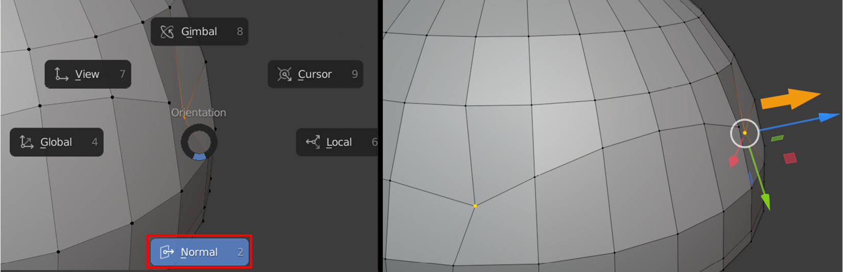
Figure 2.12 – (A) Using the Transform Orientation Pie menu to select the Normal orientation; (B) Using the z axis in the Normal orientation to move the vertex away from the surface
Both of the dented surface areas have now been fixed, and now, the surface looks great! You have just learned how to choose a Transform orientation to move, rotate, or scale a mesh component. In this case, you used the Normal direction, but there are many other options available.
In the next section, we will create a cavity shape for the shoulder of the robot droid.
Modeling the shoulder cavity
Let's continue detailing the model. We want to create a cavity in the body shape; this is where the shoulder (and arms) will be attached to. Proceed as follows:
- Start by selecting the internal faces of the proposed cavity, then press I to inset these faces by 0.05 m, as shown in the following screenshot:

Figure 2.13 – (A) Selecting faces; (B) Using Inset on the faces
- While keeping the newly inset faces selected, press 1 for Vertex Selection Mode to automatically select all the vertices of these inset faces.
- Now, right-click anywhere in the 3D Viewport and select Smooth Vertices from the pop-up menu. This applies a smoothing function on the selected vertices. Repeat this five times. Your mesh should now resemble Part B of the following screenshot:

Figure 2.14 – (A) Selecting vertices; (B) Applying smoothing
- With the vertices still selected, press the Rotate icon on the toolbar to activate the Rotate Object gizmo. Start to rotate the vertices very slightly on the y axis (the green circular handle on the gizmo) until the Operator panel opens up in the bottom left of the 3D Viewport.
- Open this minimized Operator panel and change Angle to -12°, as seen in Part A of the following screenshot. Now, move the selected vertices -0.025 m on the X axis, as shown in Part B of the following screenshot:
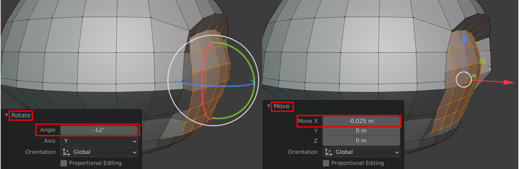
Figure 2.15 – (A) Rotating the selection; (B) Moving the selection
- Extrude the faces inward by -0.006 m on the z axis, as seen in Part A of the following screenshot. Now, add a loop cut at a factor of -0.5 on the inside faces of the cavity, as seen in Part B of the following screenshot:

Figure 2.16 – (A) Extruding the faces; (B) Adding a loop cut
The body of the robot drone is starting to look really interesting. In this section, you've learned how to change the shape of a mechanical mesh surface by creating a cavity shape for the drone's shoulder.
In the next section, we will use the Mirror modifier to copy our work to the opposite side of the mesh. Then, we will take that model one step further by adding the last bit of polish.
Mirroring and adding polish to the mesh
The block-out for the robot drone's body is almost done, but we need to copy all the hard work that we have done on the body's left side over to the right side. Here's how we can accomplish this:
- Delete the right-hand side of the mesh by selecting the faces on the right-hand side and then pressing the Delete key.
- Use the Mirror modifier (as explained in Chapter 1, An Introduction to Blender's 3D Modeling and Sculpting Tools).
- Apply the modifier by switching to Object Mode, then in the Properties panel, click on the Modifier Properties tab (as shown in Part A of the next screenshot). Inside the properties of the modifier, you will see a small downward-pointing arrow.
- Click on this arrow, and in the drop-down menu that opens, select Apply, as shown in Part B of the following screenshot). Another quicker way to apply the modifier is by using the Ctrl + A shortcut while your mouse pointer is hovering over the modifier:

Figure 2.17 – (A) Selecting the Modifier Properties tab icon; (B) Clicking on the arrow and selecting Apply from the drop-down menu
Note
This process of applying a modifier can be used for all modifiers in Blender.
Now that the mesh has the cavity feature on both sides, it's time to move on to the polishing stage.
First, we will subdivide the model, then we will choose a selection of edges to bevel.
The reason we will do it this way is that the shape of the model is generally quite smooth already, even with only one additional level of subdivision, but some edges are still too sharp-looking and would need to be rounded off (beveled) manually. To do all this, just follow these simple steps:
- Select the mesh. While in Object Mode, press Ctrl + 1 to add a Subdivision Surface modifier with one level of subdivision to the mesh. Apply the modifier as you did for the Mirror modifier.
- Select the edges that run around the middle of the body shape, but don't select the edges inside the cavities, as shown in Part A of the next screenshot. You can do this by holding Ctrl while selecting the beginning and then selecting the endpoint for the edges you want to select. This way, it will automatically select the edges between your beginning and end points.
- Press Ctrl + B to bevel these edges and select a Width value of 0.0223 m and use two segments, as shown in Part B of the following screenshot:
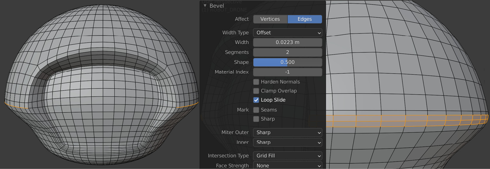
Figure 2.18 – (A) Selecting edges; (B) Adding a bevel
- Press Shift + Alt and left-click to select the outer two edge loops of the cavity,as shown in Figure 2.19, Part A.
Apply a bevel with a Width value of 0.0087 m and set the Segment value to 2, as shown in Figure 2.19, Part B.
Note
Holding Shift while selecting edge loops will add to your current selection.

Figure 2.19 – (A) Selecting edge loops; (B) Adding a bevel
You have completed the body shape for the robot drone and have learned how to mirror your work from one side of a mesh to another side. You have also learned how to smooth out the shape of the mesh by using the Subdivision Surface modifier and by using the Bevel function on certain edges.
In the next section, we will create some eyes for the robot drone.
Creating eyes
Let's model some robot eyes for our robot drone, as follows:
- Start by adding a Cylinder mesh by using the same method that you used when you added the UV Sphere mesh.
- Move, rotate, and scale the Cylinder mesh to fit it over the reference image, as shown in the following screenshot:

Figure 2.20 – Fitting the Cylinder mesh over the reference image
- Select the inside vertices of the Cylinder mesh and scale and move them to create the shape shown in the following screenshot:
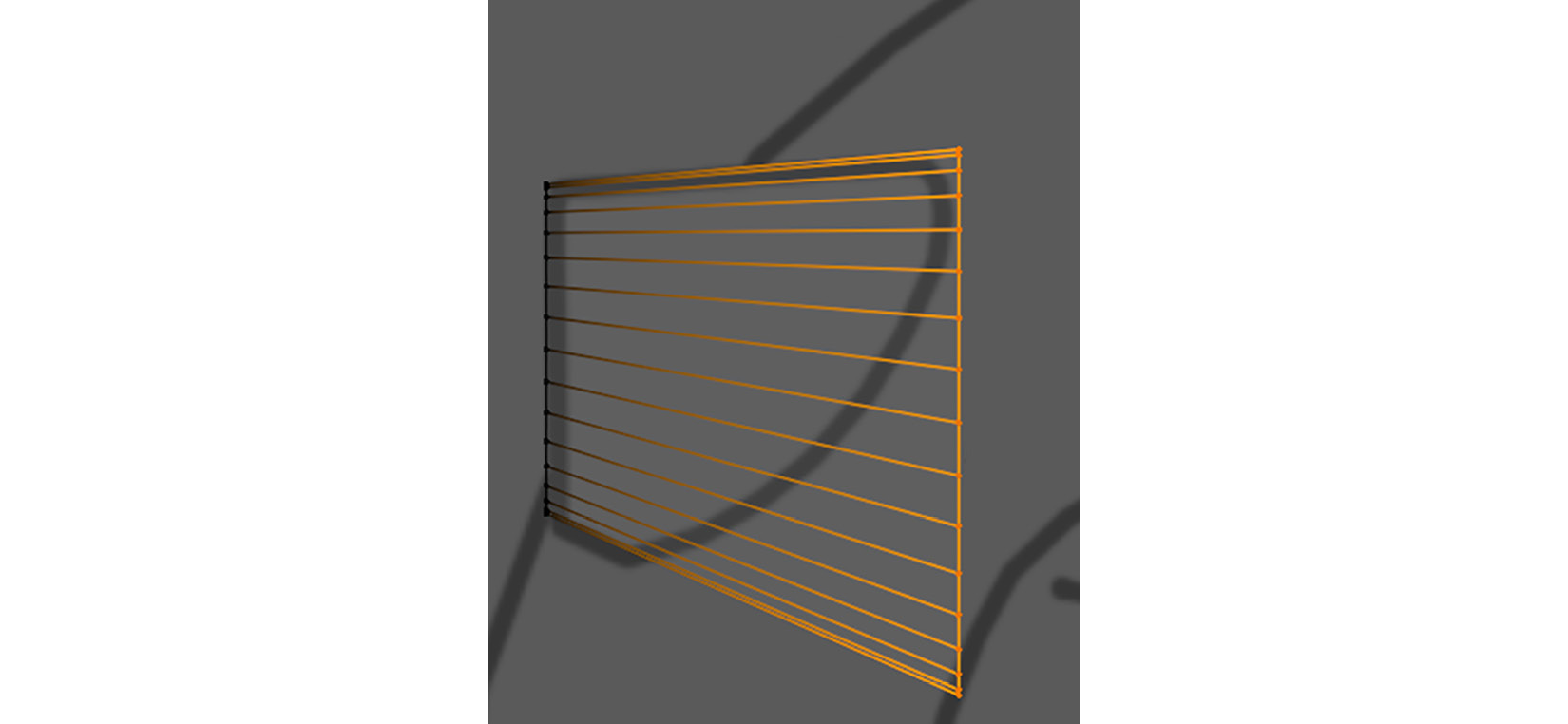
Figure 2.21 – Scaling the inside vertices
The result should look like the selected model in the following screenshot:

Figure 2.22 – The result
- Select the outside edge loop of the Cylinder mesh and then bevel it. Select the inside face and then inset the face slightly, as shown in the following screenshot:
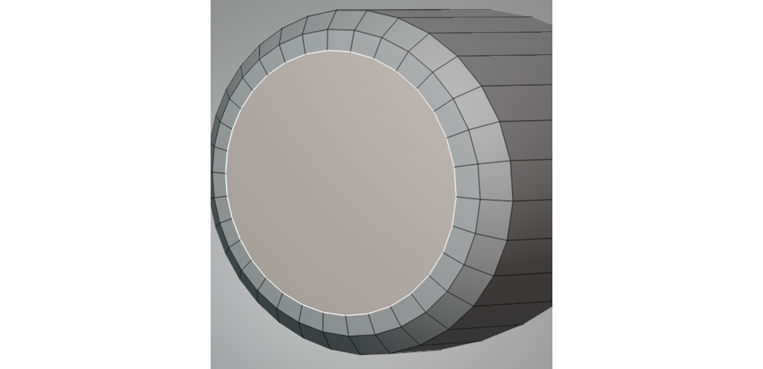
Figure 2.23 – Beveling the outer edge and insetting the inside face
- Extrude the face inward and scale it down slightly, as shown in the following screenshot:

Figure 2.24 – Extruding the inside face
- Continue to use the Inset tool to make eight more incremental insets. Make one last inset and select its vertices. Press M to open the Merge menu, then select At Center to merge them into one vertex. The end result can be seen in the following screenshot:

Figure 2.25 – Continuing to add eight more insets and merging the ninth inset so that it creates a vertex in the center
- We want to turn the flat inner faces of the robot drone's eye into a bulging shape so that it looks like a lens. To do this, select the center vertex. Press O to turn on Proportional Editing, or you can click on the Proportional Editing icon in the Header bar. Move the vertex outward by -0.01 m in the Y axis. In the Operator panel, select Sphere as the shape for the Proportional Falloff setting, and set Proportional Size to 3.35, as shown in the following screenshot:

Figure 2.26 – Using Proportional Editing for the lens shape
- For the last polishing step, bevel the sharp outer edges of the robot drone's eye, as shown in the following screenshot:

Figure 2.27 – Adding bevels
- Now, you need to mirror the eye. With the robot drone's eye mesh selected, switch to Object Mode. Press Ctrl + A to bring up the Apply Object Transformation menu, and choose All Transforms to set the mesh's origin to the center of the scene. This is because Blender can use the point of origin as the center of the Mirror function.
- Use the Mirror modifier to mirror the left-hand-side robot eye to the right-hand side (the Mirror modifier was covered in Chapter 1, An Introduction to Blender's 3D Modeling and Sculpting Tools).
You have just completed the robot drone's mechanical-robot-eye model. In this exercise, you've learned to create a bulging shape with the Proportional Editing tool and practiced how to refine the shape by adding more bevels and insets.
In the next section, we will create the robot drone's shoulders and shoulder ball joint. This is where the arms will be attached to.
Adding a shoulder and a ball joint
Now, we will quickly model the shoulder (made from a Cylinder mesh) and add a Sphere mesh that will be the ball joint. A ball joint is a mechanical joint in engineering that can rotate in any direction. Follow these next steps:
- Create another Cylinder mesh. Move, rotate, and scale the cylinder into the position shown in the following screenshot. This cylinder is the robot drone's shoulder:

Figure 2.28 – Placing the cylinder that forms the robot drone's shoulder mesh
- Select the outer face of the shoulder and inset it by 0.0106 m, as shown in the following screenshot:

Figure 2.29 – Insetting the face on the shoulder
- With the face on the shoulder still selected, extrude it inward by 0.06 m on the x axis, as shown in the following screenshot:

Figure 2.30 – Extruding the face on the shoulder
- Now, select the outer edge loop of the shoulder and bevel the width by 0.0067 m, as shown in the following screenshot. The shoulder disk is now complete:

Figure 2.31 – Beveling the edge loop on the shoulder
- Now, we will create a ball joint for the end of the shoulder. Create a UV Sphere mesh. This sphere will be the ball joint. Position the sphere halfway inside the shoulder, as shown in Part A of the following screenshot. Then, delete the faces that are hidden inside the cylinder, as shown in Part C of the following screenshot:
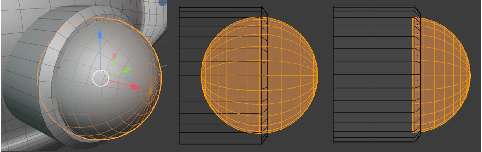
Figure 2.32 – (A) Adding the ball joint (sphere) to the shoulder disk mesh; (B) Wireframe side view of the same ball joint; (C) Wireframe side view of the ball joint with deleted faces
- Mirror both the shoulder mesh and the ball-joint mesh to the right-hand side of the model by using the method that was explained in the Creating eyes section. The result should look like this:

Figure 2.33 – Mirroring the ball joint and the shoulder mesh
You have just completed the shoulder and ball-joint part of the model. In this section, you have learned to use extreme precision to position one mesh very accurately into another mesh. In the next section, we will explore how and why we can add some KitBash meshes to the model.
Attaching a KitBash mesh
So, what does KitBash mean? KitBashing (also called model bashing) is a practice whereby a model (or part of a model) is created from existing model parts to save production time.
This way, artists can rapidly add details to their model by using a library of pre-made smaller model parts.
As a 3D artist and 3D movie maker, you should organize and save bits of the models you create. This way, you can build up your own KitBash library.
I have prepared a Kitbash_models.blend KitBash model library file, which you can download from the online repository here: https://github.com/PacktPublishing/Unreal-Engine-5-Character-Creation-Animation-and-Cinematics/tree/main/Chapter02.
This file contains five KitBash model parts that you can use for your models. In the following screenshot, I am showing two views of this KitBash model library:

Figure 2.34 – KitBash model library
Load the Kitbash_models.blend file into Blender. Place any one of these KitBash models from the file onto the body of the robot drone. For the purpose of this tutorial, I have used the Booster_V1 model from the KitBash model library (Kit-Bash_models.blend). This is the model that is highlighted by yellow rectangles in Figure 2.34.
It is advisable to place only one KitBash model on your robot drone; otherwise, you will have more models to UV unwrap and texture in the tutorial presented in Chapter 4, UV Maps and Texture Baking.
I loaded the Booster_V1 model and positioned it in the place that was indicated in the reference image, and then I used the Mirror modifier to mirror it to the other side. The result of the mirrored Booster_V1 model can be seen in the screenshot shown next.
Feel free to be creative and come up with some of your own interesting KitBash placements, using this representation as a starting point:

Figure 2.35 – The Booster_V1 model placed on the body and mirrored to the other side
In this section, you've learned how to save lots of production time by using a library of pre-made 3D assets to quickly add visual details to your models.
In the next section, we will start to model the mechanical arms of the robot drone.
Handy Tip
While going through the tutorials in this book, you will find it helpful to take a break every now and then, just to practice some of the new tools and techniques that you've just learned about. This is a good test for you, to see what you've learned so far and— more importantly—which information you've retained so far. Afterward, continue from where you left off with your chapter's project.
Modeling the arm
Let's start with the last part of the robot drone that we need to model—the arms. Proceed as follows:
- Unhide the reference image for the mechanical arm in the Outliner panel. You will now see the mechanical-arm reference image is visible in the Right Orthographic view.
- Create a Cylinder mesh. Move, rotate, and scale the Cylinder mesh into the position of the shoulder's black outline, as seen in the reference image indicated by the orange outline in the following screenshot. This cylinder will be the robot drone's shoulder disk:
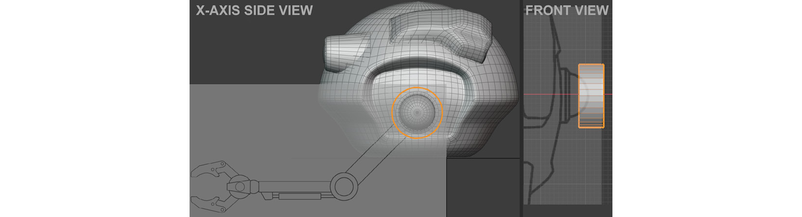
Figure 2.36 – Revealing the reference image and placing the cylinder for the shoulder disk
- Select the outer edge loop of the shoulder disk and bevel it with one segment so that your shoulder disk looks similar to the model shown in the following screenshot:

Figure 2.37 – Big bevel for the outer edge of the shoulder disk
- Select the two outer edge loops on the shoulder disk and then bevel them by a small amount, using two segments as shown here:
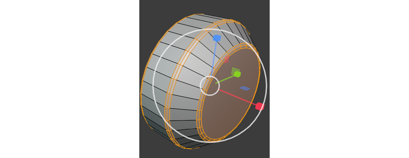
Figure 2.38 – Small bevels for the circular edge loops of the shoulder disk
- Duplicate the shoulder disk. Move and scale it into the position of the elbow disk's black outline, as shown in Figure 2.36. This duplicated mesh will be the robot drone's elbow disk.
- Extrude and bevel the right side of the elbow disk, as shown in the following screenshot:

Figure 2.39 – Extruding and beveling the elbow disk
- Duplicate the elbow disk. Move and scale it into the position of the claw disk's black outline that is shown in the reference image. This duplicated mesh will be the robot drone's claw disk, as shown in Figure 2.40.
- Create another small Cylinder mesh. Position this mesh to fit in the center of the claw disk.
- Now, we will create and place rectangular-shaped meshes for the upper and lower arm. Create a Cube mesh. Move, rotate, and scale this mesh into the position of the upper arm's black outline that's shown on the mechanical-arm reference image.
- Bevel the edges of this rectangular-shaped mesh, which used to be a Cube mesh before you scaled it.
- Create another Cube mesh. Move, rotate, and scale this new Cube mesh into the position of the lower arm's black outline, as in Figure 2.40.
- Bevel the edges of the rectangular-shaped meshes, as shown in the following screenshot:

Figure 2.40 – Placement of all disks and rectangular shapes; note there is a small cylinder inside the wrist's disk
You've just created all required disk shapes and rectangular shapes for the shoulder, upper arm, elbow, lower arm, claw cylinder, and the small claw cylinder that is inside the claw cylinder, as shown in Figure 2.40.
You've learned how to accurately place geometry to match the reference image and add polish to these elements by beveling them.
In the next section, we will go on to model some of the smaller elements that can be seen in the reference image—the forearm piston, wrist ball joint, and claw disk holder.
Piston and wrist detailing
We now start on the mechanical arm's smaller details, as follows:
- Create a Cube mesh. Position this mesh in the center of the wrist disk. This will be the claw disk-holder mechanism shown in Figure 2.41, Tag A.
- Extrude the very front face of this Cube mesh and scale it down slightly. Then, modify the form of this Cube mesh to create the shape shown in Figure 2.41, Tag A.
- Bevel the claw disk-holder mechanism.
- Create a UV Sphere mesh. Move this mesh into the position shown in the reference image. This UV Sphere mesh is the wrist ball joint of the robot droid, as shown in Figure 2.41, Tag B.
- Create another Cube mesh. Position this mesh at the bottom of the lower arm. This Cube mesh will be the forearm piston connector, as can be seen in Figure 2.41, Tag C.
- Bevel the forearm piston connector. For this task, you would first need one big bevel applied to the outer edge near the piston. Then, bevel all the edges with a smaller-sized bevel.
- Create two Cylinder meshes. One of the Cylinder meshes should be half as long as the other one, but it should be double in diameter.
- Position these two Cylinder meshes so that the thinner cylinder is inside the center point of the wider cylinder to form the forearm piston, as shown in Figure 2.41, Tag D.
- Place this forearm piston (the two Cylinder meshes) into the position of the piston's black outline.
- Bevel the outer edge loops of the wider Cylinder mesh that is part of the forearm piston, as shown in Figure 2.41, Tag D.
Your model parts should now look like the models shown here:

Figure 2.41 – Different views of the lower arm showing the four model parts (tags A-D)
You've just learned how to model a variety of mesh shapes and place them into accurate positions, according to what is shown in the preceding screenshot.
In the next section, we will start with the robot droid's claws.
Creating claws
If you look at the reference image, the robot droid's claws might look really complex, but they are actually really simple to model. Let me show you this method in the following steps. We will start on the far-left side of the upper claw:
- Press the numpad key 3 to switch to the Right Orthographic view. Create a very small Cube mesh near the claw section of the reference image.
- Switch to Edit Mode and Vertex Selection Mode. Press A to select all the vertices of the cube, then press M to merge and choose At Center from the pop-up menu, as illustrated in the following screenshot:

Figure 2.42 – Positioning the cube and selecting At Center merge
- You will see that the Cube mesh has now been replaced by a single vertex, as shown in the following screenshot:

Figure 2.43 – The result is a single vertex
- Press G for Move Mode. Then, move the vertex to anywhere on the outline of the claw that is shown in the reference image.
- While still in Move Mode, press E to extrude the vertex. Move the mouse pointer to another spot close by on the outline of the claw. You will see that an edge is being drawn as you move your mouse pointer. Left-click to place a new vertex, as shown in the following screenshot:

Figure 2.44 – Extruding the vertex to create edges that follow the outline of the claw
- Repeat the process to create more edges until you've traced the complete outline of the upper claw in the mechanical-arm reference image. Once you have traced all around the outline of the upper claw, place your last vertex close to the starting point.
- Now, select two vertices that are close to each other and press M to merge them, as shown in the following screenshot:

Figure 2.45 – Completing the outline trace and merging vertices that are close together
You've just learned how to draw a custom shape made out of edges, by using Extrude Function on a single vertex. In the next section, we will take this shape and create the front part of the claw from it.
Extruding the custom shape
You now have an outline made up of edges and vertices, but it doesn't have any faces yet. Let's learn how to add a face to the selected edges, then take it further by converting this new face into a full 3D shape in the following steps:
- To create a face for the edges you made earlier, you just need to select all the edges and then press F to fill the edges with a face, as shown in the following screenshot:
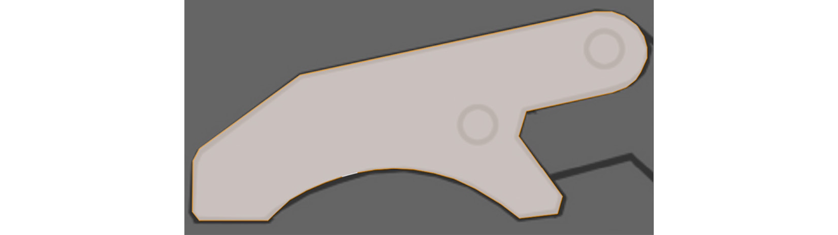
Figure 2.46 – Filling the edges to create a face
You have now created a custom face. This face is the shape of the front part of the upper claw. Let's give this face some thickness.
- Select the face. Press E to extrude the face in the x-axis direction by 0.0125 m. Your custom outline made of edges will now have a solid 3D form, as shown in Figure 2.47.
- Add small disks to areas where bolts are indicated in the reference image. Do this on both the left-hand and right-hand sides of the front part of the upper claw, as shown in Figure 2.47.
- Repeat the same process for the inner part of the upper claw. To add some variation to the mesh shapes, you should make this part a bit thinner than the front part of the upper claw. The result should look like this:

Figure 2.47 – Extruded faces for the upper claw
- Now, we will bevel all the sharp angles of the claw to make it look like the other model parts. Fortunately, there is an easy way to select all sharp angles on your selected mesh. Switch to Edit Mode with edge selection activated. In the Header bar, navigate to Select | Select sharp edges.
- All the sharp edges are now selected on your mesh. Now, bevel these edges slightly to complete this part of the model. Use the following screenshot as a visual guide for your bevel width:

Figure 2.48 – Beveling sharp edges
- With all these parts completed, switch to Object Mode and select all the different model parts of the upper claw, and press Ctrl + J to join them all together so that they become one mesh.
- Keep the claw mesh selected. In the Header bar, navigate to Object | Set Origin | Origin to Geometry to set the origin of the mesh to the center of the geometry.
- Use the Shift + D shortcut to duplicate the upper claw. Press N to bring up the Properties region menu. In the Rotation section of the Properties region menu, set the y axis to 180 to rotate the claw mesh, as seen in the following screenshot:

Figure 2.49 – Using the Properties region to type in the rotation of the duplicated claw
- Manually move the duplicated claw mesh downward in the (blue) z axis so that it fits in the position of the outline of the lower claw shown on the mechanical-arm reference image, as illustrated here:
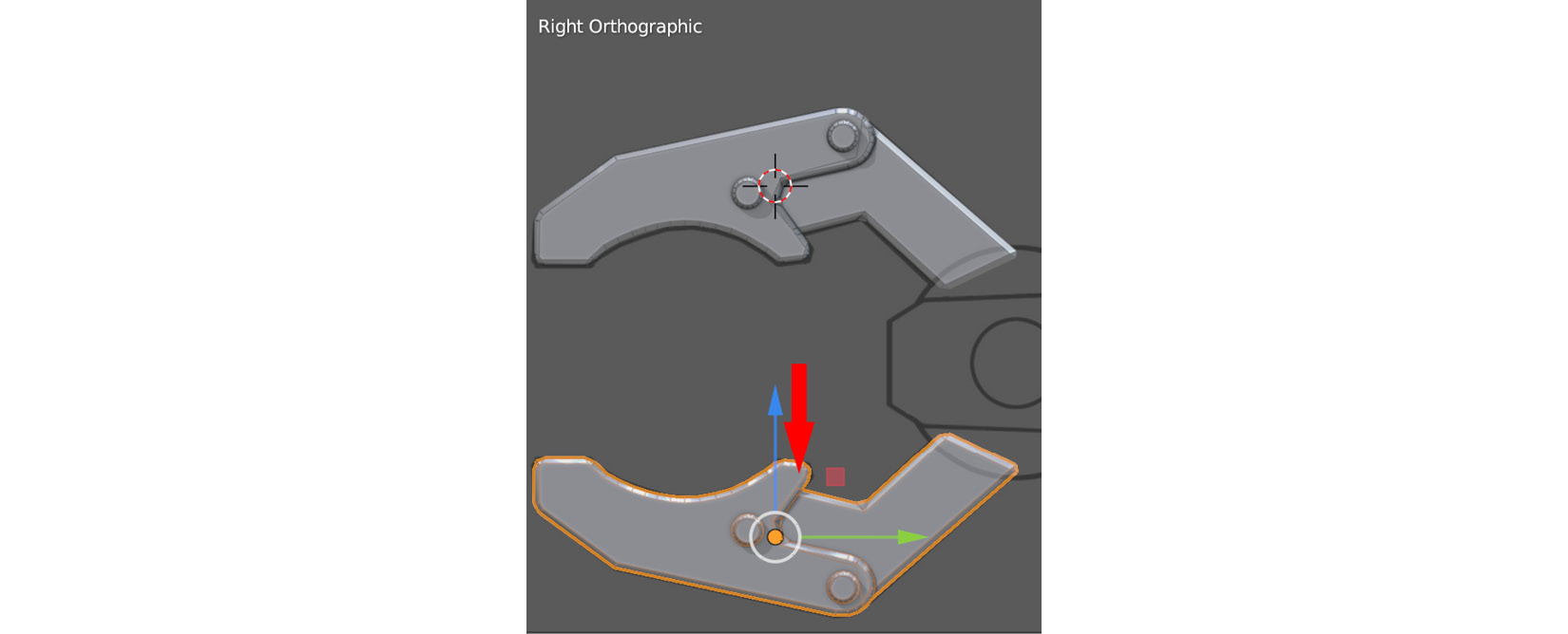
Figure 2.50 – Moving the duplicated claw to match the claw's outline in the reference image
With both the upper and the lower claw done, your claw model should now resemble the model shown in Figure 2.50.
- Mirror each mesh part in the arm and shoulder to the right side (using the same method explained in the Creating eyes section). Your completed model should now look like the one shown in Figure 2.51.
- Save the robot drone model in the Blender file format (.blend).
Congratulations! You have successfully completed the robot drone practical tutorial.
In this section, you have learned how to take a shape made up of edges and vertices and turn that into a full 3D mesh that you then polished off by adding smaller details such as bolts and bevels.
You've also learned to quickly select the sharp edges of your mesh so that you can bevel them. Take a look at the completed Robot Drone model here:

Figure 2.51 – The completed Robot Drone model from different viewing angles
Summary
You have now successfully completed your first practical modeling tutorial using Blender! Modeling tools work great for models such as robot drones because these tools are ideally suited for mechanical types of models, although there are no limitations to the kinds of 3D assets you can create by using these tools and methods.
One of the amazing skills you have now learned is the ability to follow reference images to guide your 3D modeling so that the final result is very accurate.
Furthermore, you've acquired other skills such as manipulating meshes in the 3D Viewport, extruding faces and vertices, beveling edges, and subdividing meshes to smooth out the block-out shape, and you've also learned how to build custom-shaped faces that you can then turn into 3D meshes.
You now have both the practical experience and theoretical knowledge from Chapter 1, An Introduction to Blender's 3D Modeling and Sculpting Tools to create your very own 3D assets for your 3D movie.
For creating organic types of models, there is a more efficient way to create them using a very different workflow...this method is known as 3D sculpture.
In the next chapter, we will continue our journey by learning about 3D sculpture using Blender to create some amazing organic types of models.
You will be guided in a step-by-step practical 3D sculpting tutorial to create an Alien Plant 3D asset for your sci-fi-themed 3D movie.