
Chapter 1: An Introduction to Blender's 3D Modeling and Sculpting Tools
Welcome to the exciting world of 3D movie making!
We know you are super eager to start making your first 3D movie, but before you can do that, you need to get virtual actors, virtual sets, and virtual props, just like in a (virtual) Hollywood movie.
To create these 3D assets, you will need to learn how to use a piece of 3D software called Blender. This 3D creation suite is open source (free to use).
In this chapter, we will cover two approaches to creating 3D assets in Blender: 3D modeling and 3D sculpting.
I will start by explaining the very basic concepts of 3D modeling, then delve into the differences between 3D modeling and 3D sculpting and which is the best suited for a particular task.
After this, you will get a quick overview of how to use Blender by learning how to use the user interface, navigate in the 3D Viewport, view modes, and manipulate and select items.
Finally, we will briefly explore some of the most used 3D modeling tools, 3D sculpting tools, and modifiers that we will use in the practical exercises throughout the next four chapters.
Note
This chapter's purpose is to introduce you to the fundamentals of 3D graphics in general and the basic functionality of Blender's 3D modeling and sculpting tools. It is not meant as a practical chapter but rather as a reference of the tools that are used in Blender.
In this chapter, we're going to cover the following main topics:
- What is 3D modeling?
- Understanding 3D sculpting
- Introducing Blender
- Exploring Blender's modeling tools
- Using modifiers in Blender
- Exploring Blender's sculpting tools
- Other sculpting tools
By the end of this chapter, you will have a thorough understanding of the basic concepts of 3D modeling and sculpting.
You will learn the basics of Blender's functionality and learn about the 3D modeling and sculpting tools that you will use in the upcoming chapters.
Technical requirements
You will need the following hardware and software to complete this chapter:
- A computer that can run basic 3D animation software
- Blender, which can be installed from https://www.blender.org/download/
The Blender version that's used in this chapter is version 2.93.4. Even if your version of Blender is newer, the examples should still work without any problems.
Before we dive into the 3D movie-making process, you need to understand the basic concepts of 3D modeling.
The files related to this chapter are placed at https://github.com/PacktPublishing/Unreal-Engine-5-Character-Creation-Animation-and-Cinematics/tree/main/Chapter01
What is 3D modeling?
3D modeling is the process of creating 3D models by manipulating Meshes in 3D software.
A mesh (also called a polygon mesh) is a three-dimensional virtual object that is represented in a three-dimensional space in the 3D software.
A mesh is made up of components. These components are faces, edges, and vertices:
- A face is best described as a filled-in plane with at least three or more straight edges. Faces are made of two sub-component parts – edges and vertices.
- An edge is a connection between two vertices.
- A vertex (plural: vertices) is a point in a 3D space. Vertices are the smallest components of a mesh.
These can be seen in the following diagram:
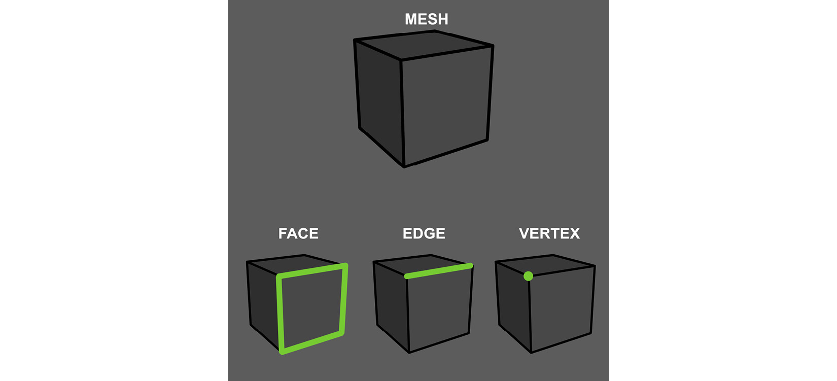
Figure 1.1 – The parts of a mesh
In this section, you learned about the basics of 3D modeling. This knowledge is an essential building block to learning more about 3D graphics.
In the next section, we will explore the fundamentals of 3D sculpting as a different approach to creating 3D assets.
Understanding 3D sculpting
So, what is 3D sculpting and how is it different from 3D modeling?
3D sculpting or digital sculpting can best be described as shaping or forming a 3D mesh with brush-based sculpting tools.
Imagine a traditional sculptor who is modeling in clay. Now, with modern computer graphics software such as Blender, you could sculpt much like a traditional sculptor but in a virtual three-dimensional space by using a pressure-sensitive graphic tablet and pen, or a mouse.
In Blender, we have many sculpting tools available that approximate the feeling of digital clay.
The benefit of a sculptural approach to creating models is that it can be more intuitive for creating organic shapes instead of using regular modeling tools (which are usually better suited for mechanical meshes or models of man-made structures such as buildings, vehicles, and so on).
Some examples of organic shapes for 3D sculpting include human bodies, creatures, animals, plants, rocks, and any other natural organic-shaped solid form. For 3D sculpting, we also use polygon meshes.
In this section, you learned about the basic concepts of 3D sculpting.
In the next section, you will learn about the essential functionality of Blender, which includes its user interface, navigation, and much more.
Introducing Blender
Blender is a 3D creation suite that can create almost any virtual scene or object.
We'll start exploring Blender by learning about the user interface that you see before you. Knowing what is where is the most essential starting point.
The user interface
As we open up Blender for the first time, we are greeted with a splash screen. This is a helpful menu to get you started when you have a particular project in mind. But for now, just close this menu. Once you've closed the splash screen, your view should look similar to what's shown in the following screenshot:
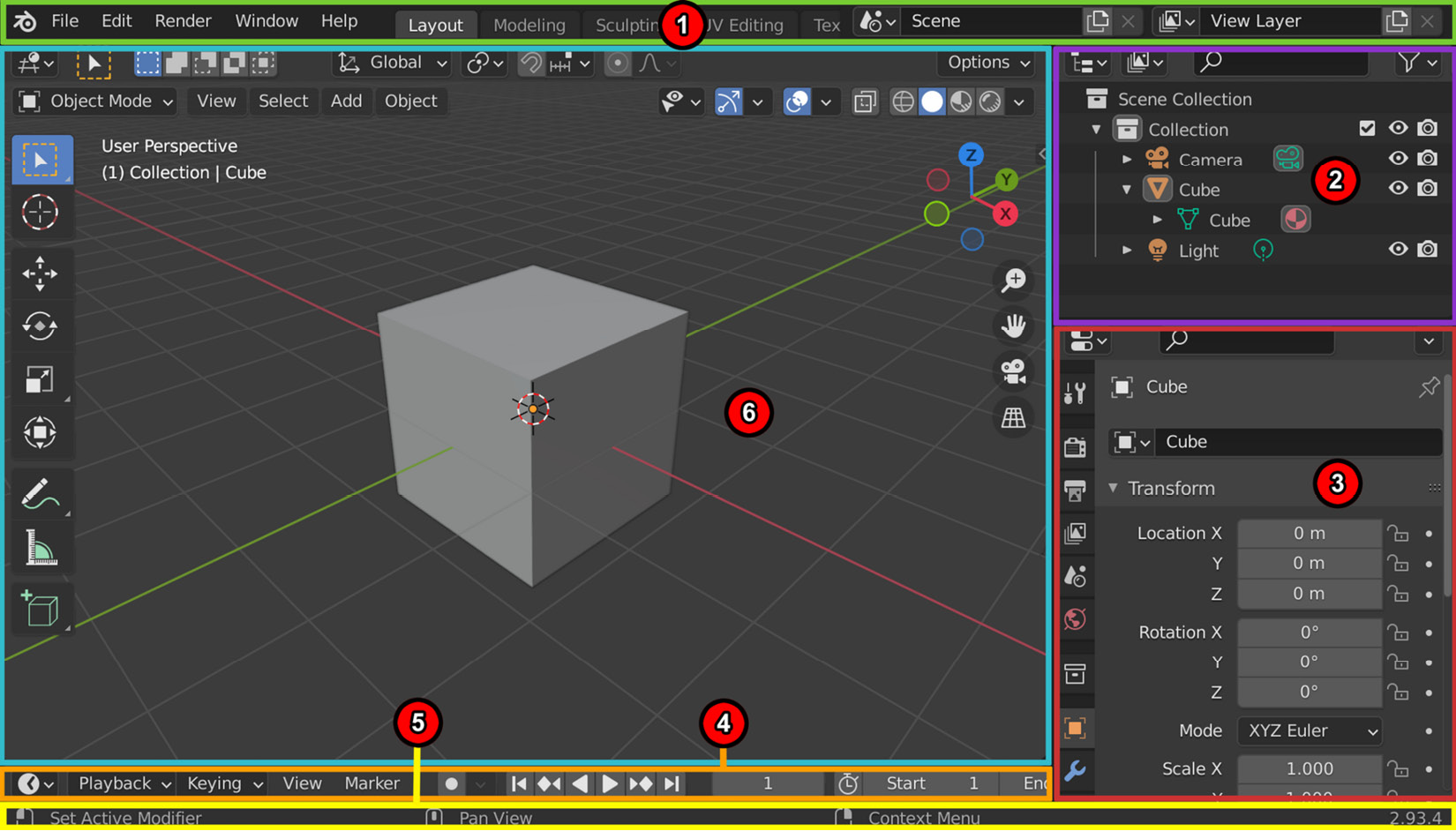
Figure 1.2 – Blender's user interface regions
The numbered areas in the preceding screenshot mark the different user interface regions that I will explain:
- Topbar: This contains menus such as File, Edit, Render, and Help. On the right of that, we have tabs for selecting workspaces. These are like modes for the software, complete with menus and shortcuts. For example, if we want to move objects around the scene, we can use the Layout Workspace tab. Later, when we want to learn about the modeling process, we can switch over to the Modeling Workspace tab.
And, as you have probably already guessed, for 3D sculpting, we can use the Sculpture Workspace tab. The last few tabs we will cover in this book are the UV Editing Workspace and Texture Paint Workspace tabs. Some of the other tabs that you will need for your future projects are the Shading Workspace and Animation Workspace tabs.
- Outliner: This is a list representation of the various objects (meshes, curves, and so on) and elements (cameras, lights, and so on) in the scene. The Outliner can be used for selecting, deselecting, hiding, and organizing these objects and elements in the scene.
- Properties: Here, we will find adjustable properties with tabs for adjusting active data, including the scene and its objects.
- Timeline: This is used for scrubbing and manipulating animation keyframes.
- Status Bar: This is where Blender displays contextual information about mouse and keyboard shortcuts and other statistical information.
- 3D Viewport: This is where you can view what is happening in your virtual 3D world.
In this section, you learned about the basic layout of Blender's user interface and its regions. In the next section, we will take an in-depth look at the various elements of the 3D Viewport.
Elements in the 3D Viewport
The 3D Viewport is where you can view what is happening in your virtual 3D world. The grid pattern shows you the floor plane. The floor grid plane is positioned at 0 on all three axes:

Figure 1.3 – The 3D Viewport's UI elements, shown with the Layout Workspace active
There are a few important items and regions in the 3D Viewport, as highlighted in the preceding screenshot:
- The Header bar: This menu bar acts as a container for menus and commonly used tools. Menus and buttons will change with the editor type and the selected object and mode.
- Toolbar: This menu bar contains a set of interactive tools that change depending on the workspace that's been selected. To show or hide the toolbar, press T.
- Properties region, also known as the N-panel: The Properties region can't be seen in the preceding screenshot because it is hidden by default. To open the Properties region, press N. This will open the Properties region on the right-hand side of the 3D Viewport. The Properties region holds settings for the 3D view and active object. It also provides numeric inputs for editing the Transform tab of your selected item (Location, Rotation, Scale, and Dimensions), as shown in the following screenshot. You can also use the Properties region to edit your 3D view's focal length and viewport clipping:

Figure 1.4 – The Properties region
By default, the 3D Viewport will show you some additional items that are automatically loaded on startup. These are the 3D cube mesh, the camera, and the light:
- The 3D cube mesh is a model that provides a good starting point for many modeling tasks.
- The camera is a virtual camera that's used for renders inside Blender, while the light is a virtual light that's used to light our scenes. Neither of these will be used for our tutorial, so we can delete them.
- We also have the object origin. If we focus our attention on the 3D cube mesh in the center of our view, we can see that there is a tiny orange dot right in the center. This indicates the object origin point of our mesh. We will discuss why it is of importance later.
- The 3D cursor is a red-and-white striped circle with crosshairs. This is a very useful tool that will be discussed later.
- Finally, we have the Navigation Gizmo, which can be found in the top-right corner of the 3D Viewport. You can use this gizmo to rotate your view of the 3D scene. We can either click and drag on the navigation gizmo to smoothly change our view, or we can click on one of the dots, which will immediately snap our view to one of the Orthographic views.
Note
Orthographic views are two-dimensional views of a 3D object or scene. These are usually front, back, right, left, top, and bottom Orthographic views.
In this section, you learned about the different elements of the 3D Viewport in Blender. So, now that you have an understanding of the basic user interface, let's continue our journey and learn more about the basics of Blender.
In the next section, we will explore how we can interact with items in the 3D Viewport.
Interacting with the 3D world in Blender
In Blender, there are three basic ways to navigate inside the 3D Viewport – that is, to change your viewpoint of the 3D scene.
Navigating around the 3D view
The following three methods change your viewpoint and can be used to navigate inside the 3D Viewport:
- Zoom: Use the mouse scroll wheel to zoom in or out from the object. Alternatively, you can use Ctrl + click and drag using the middle mouse button to zoom in or out.
- Rotate: Click and drag while pressing the middle mouse button. Hold Alt + click and drag using the middle mouse button to snap the view to the Orthographic view.
- Pan: Press Shift + click and drag using the middle mouse button to pan. Panning means moving the viewpoint from side to side.
Now that you understand how to change your viewpoint in the 3D scene, let's explore how we can interact with items in the 3D Viewport.
Selecting and deselecting items
Once you close the splash screen in Blender, the first thing you will see is a view with a 3D cube in the center.
By default, the 3D cube is already selected. We know this because the 3D cube is highlighted with an orange outline. If an item or component is deselected, it will have no orange outline.
Note
When an item is selected in the 3D Viewport, that same item will also be selected and highlighted in the Outliner. You could use the Outliner to select or deselect items. Any selected/deselected items will also be automatically selected/deselected in the 3D Viewport.
There are a few more ways to select or deselect items, objects, or mesh components in Blender:
- Selecting items directly: Left-click on an item or component directly to select it. To deselect an item or component, you should left-click anywhere in the 3D Viewport.
- Selecting using the selection tools: The select box (located at the top of the toolbar on the left, as shown in Figure 1.3) is the default tool that's used for selection. To use this tool, press the left mouse button and drag over the items or components you want to select.
- Selecting multiple items: If you want to select multiple items at once, you can add to your selection by holding Shift when you click on an item. Clicking on an already selected item while holding Shift will deselect that item from the rest of the selected items.
To select all the items in your scene at once while in the Layout Workspace area, press A to select all. Pressing A twice in quick succession will deselect all the items in your scene.
- Selecting mesh components: By default, meshes in the Layout Workspace area are in Object Mode. To select a mesh component, you need to toggle Edit Mode so that it's on by pressing Tab.
The following diagram shows how to enter Vertex, Edge, or Face Selection mode by either using the icons shown (these can be found in the Header menu bar) or using the relevant numbers on your keyboard, as shown here:
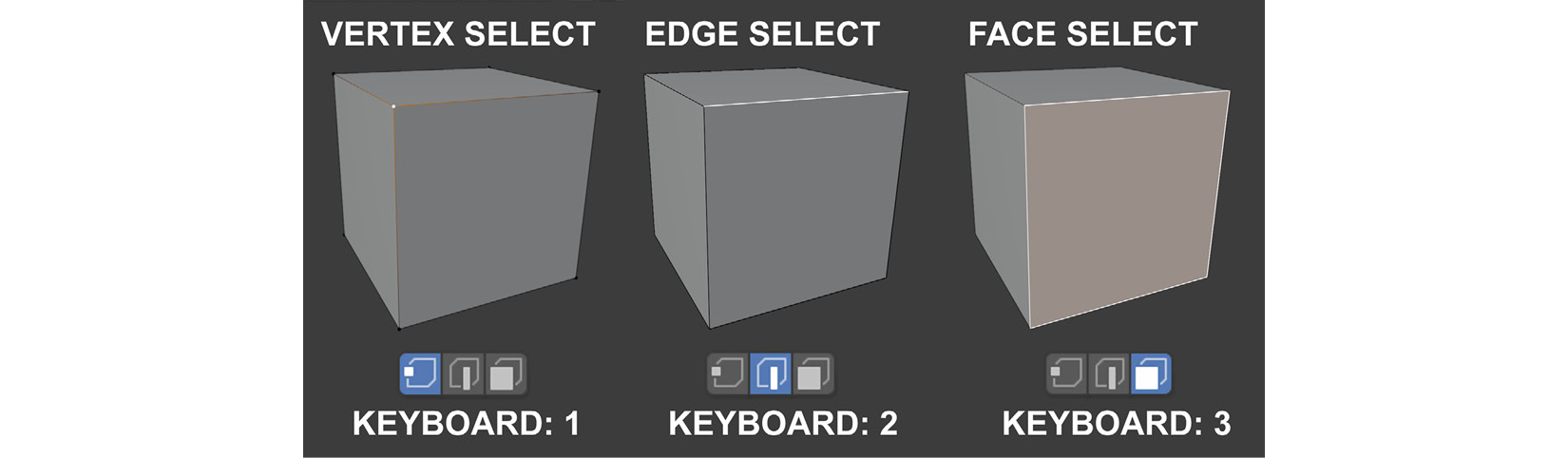
Figure 1.5 – How to select mesh components
To select any of these components for our tutorials, we will use the Box Select tool from the toolbar. Once selected, you can make a variety of edits. We will discuss how to do this later.
To toggle back to Object Mode (and leave Edit Mode), just press Tab.
- Selecting linked mesh components: There are times when you may want to select linked (connected) parts of your mesh that are a continuous mesh surface. Position your mouse cursor over the part you want to select and use the Ctrl + L shortcut. To deselect linked (connected) mesh components under your mouse cursor, press Shift + L.
In this section, you learned how to select and deselect various items and/or their components.
In the next section, we will explore the concepts of axes and transform orientations in Blender.
Axes and transform orientations
What are axes? In 3D graphics, an axis is an imaginary line in a 3D space that defines a direction. There are three axes – X, Y, and Z – that correspond to the left/right (X), front/back (Y), and up/down (Z) directional lines, as shown in the following diagram.
Axes have both a positive and a negative direction and are colored to make them easier to visually identify. The X-axis is red, the Y-axis is green, and the Z-axis is blue. In Blender and Unreal Engine (UE), the up direction is in the positive direction of the Z-axis:
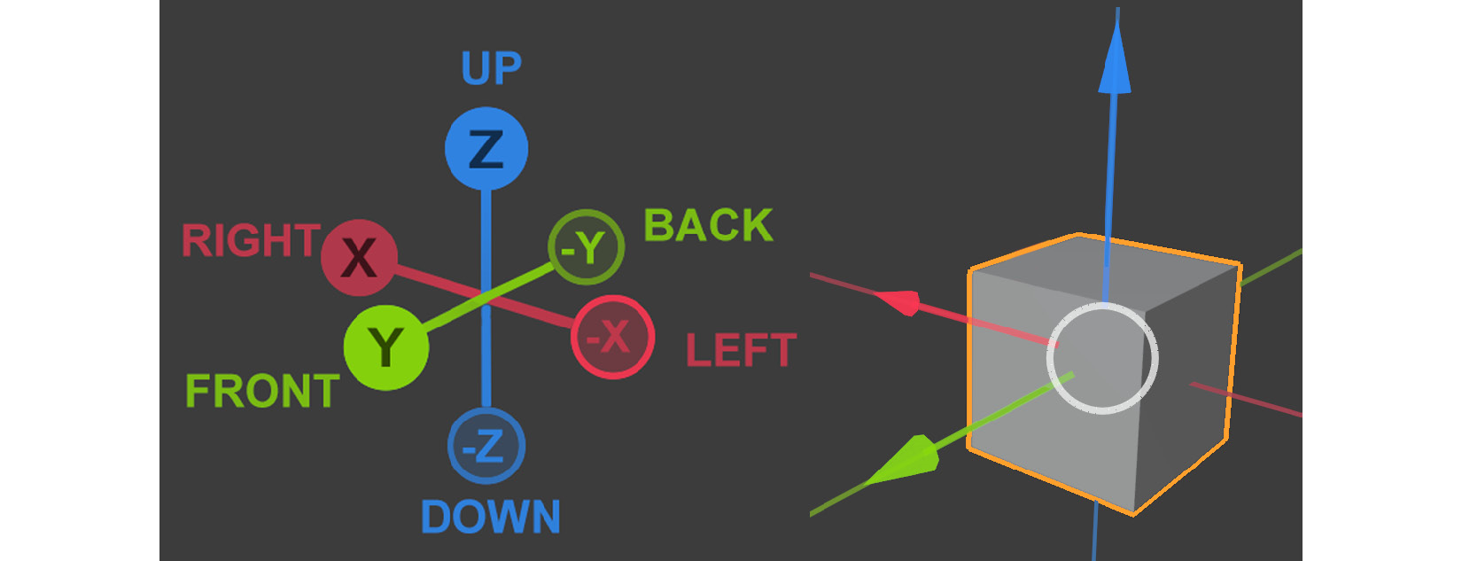
Figure 1.6 – (A) Blender's three axes: X, Y, and Z; (B) The cube serves as a reference to show how the three axes will appear on a 3D cube mesh
Now that you know what axes are, let's take a quick look at some of the other concepts you need to understand:
- Transform: Transforming an object/item means to move, rotate, or scale it. When you transform an object, you are automatically using the object's axes and the axes' orientation to transform it.
- Orientation: This describes the direction of the axes. The orientation of the axes changes, depending on the type of Transform Orientation that you choose. In Figure 1.7, you can see that the orientation of the red, green, and blue arrows (called the Object Gizmo) changes from Figure 1.7, part A, to Figure 1.7, part B.
Note
We will cover the Object Gizmo in more depth in a later section.
- Transform Orientation: This changes the behavior of transformations. In other words, the way that you transform/manipulate an object will change, depending on which Transform Orientation you choose to use. In this chapter, we will cover two of these Transform Orientation options – the Global axis and the Local axis.
To change your transform orientation using the Transform Orientations menu (drop-down menu), go to the Header bar and look for the icon with the word Global next to it. This menu is shown near the top area of the following screenshot:

Figure 1.7 – (A) Using Global (Transform Orientations); (B) Using Local (Transform Orientations)
Let's take a quick look at the difference between the Global axis and the Local axis:
- Global: The orientation of the Global axis is aligned to the world/scene. In Figure 1.7, part A, I selected the Global axis Transform Orientation for the orange-outlined box. The Global axis Transform Orientation is set as the default for all objects/items in Blender. The orientation of the Global axis is fixed and cannot be changed. All items in Blender can share the same Global axis since it is the axis of the world/scene.
- Local: Each object/item in Blender has a Local axis that is unique to the object/item/component. When the object is transformed, the Local axis will follow along. In Figure 1.7, part B, I selected the Local axis, and you can see that the axes of the orange-outlined box are following a different orientation than when we used the Global axis. Local axes are adjustable, unlike the Global axes.
You've just learned about the concepts of axes, transforms, orientations, and how to switch between the Global axis and the Local axis using the Transform Orientation menu.
In the next section, we will go over the shortcuts that can be used to transform your objects. We will also explore how to use shortcuts to switch between the Global and Local axis Transform Orientation, to speed up your workflow.
Lastly, we will explore how to use Object Gizmos as another way to transform your objects.
Manipulating objects or their components
We can manipulate objects/components by either using shortcuts or Object Gizmos. We will explore how to use both these options now. Let's start by showing you how to manipulate using shortcuts.
Using shortcuts to manipulate objects/components
Let's look at the shortcuts for moving, rotating, and scaling objects/components:
- Move: Use the G shortcut to move your selected item up, down, left, or right (perpendicular to your current viewing angle). To constrain the movement to a Global axis, hold down the X, Y, or Z key (the axes' name keys) while using this shortcut. If you press the same axis key (X, Y, or Z) a second time, it will toggle a constrain for your movement to a Local axis.
- Rotate: Use the R shortcut to rotate your selected item in either a clockwise or anti-clockwise direction (perpendicular to your current viewing angle). The item will use the object's origin (as shown in Figure 1.3) as the pivot point for the rotation. To constrain the rotation to a Global axis, hold down the X, Y, or Z key (the axes' name keys) while using this shortcut. If you press the same axis (X, Y, or Z) a second time, it will toggle a constrain for your rotation to a Local axis.
- Scale: Use the S shortcut to scale your selected item up or down. The item will use the object origin (as shown in Figure 1.3) as the center for scaling. To constrain the scaling to a Global axis, hold down the X, Y, or Z key (the axes' name keys) while using this shortcut. If you press the same axis (X, Y, or Z) a second time, it will toggle a constrain for your scaling to a Local axis.
You've just learned how to use shortcuts to transform objects and their components and other items. You've also learned that you can constrain these transforms by using the X, Y, or Z keys (the axes' name keys) and that you can switch between the Global and Local axis by pressing these keys once for the Global axis, and twice for the Local axis.
In the next section, we will learn how to use Object Gizmos to transform/manipulate objects, components, or items.
Using Object Gizmos to manipulate objects/components
What are Object Gizmos? They are transform (manipulation) tools that appear in the 3D Viewport and are overlayed on the selected item when you choose one of the three manipulation modes (move, rotate, or scale) from the toolbar, as shown in the following screenshot.
Object Gizmos offer an alternative way (another alternative to using shortcuts) to transform/manipulate objects or their components in the scene. The benefit of using Object Gizmos is that you can constrain the movement or scale to two of the three axes during a transform (constrained to a two-dimensional plane). This isn't possible when using shortcuts:

Figure 1.8 – The toolbar, with descriptions of the icons next to them. I have highlighted the manipulation modes
Let's take a look at how we can activate any of the three Object Gizmos
- Move: Use the Space bar + G shortcut or click on MOVE ICON in the toolbar, as shown in the preceding screenshot, to move with the Move Object Gizmo.
- Rotate: Use the Space bar + R shortcut or click on ROTATE ICON in the toolbar, as shown in the preceding screenshot, to rotate with the Rotate Object Gizmo.
- Scale: Use the Space bar + S shortcut or click on SCALE ICON in the toolbar, as shown in the preceding screenshot, to scale with the Scale Object Gizmo.
Once you have selected a Transform mode (move, rotate, or scale), the Object Gizmos will be overlayed over your item, as shown in the following diagram:

Figure 1.9 – The Object Gizmos overlaid over a 3D cube model for move, rotate, or scale
Inside the Move Object Gizmos, you can see that there are red, green, and blue arrows that point in three directions. These three directions represent the three axes. The red arrow represents the X-axis, the green arrow represents the Y-axis, and the blue arrow represents the Z-axis.
For example, if you want to move the cube in the X-axis direction, you should left-click and hold the red arrow and then move the mouse. This will move the cube in the X-axis direction. Then, you can release the mouse again when you want to stop moving it.
The small white circle in the middle of the Move Object Gizmo is to move the object in any direction that is perpendicular to your current viewing angle.
If you manipulate the small red, green, and blue planes near the center of the gizmo, it will constrain the movement to two of your chosen axes during a transform. For example, if you manipulate the red plane, the model's movement would be constrained to the Y-axis and Z-axis simultaneously. In other words, it would be constrained to a two-dimensional plane.
The Rotate Object Gizmo has red, green, and blue colored curves. The red curve represents the X-axis, the blue curve represents the Y-axis, and the green curve represents the Z-axis. Use these curves to rotate the selected object. The white circle that encompasses the colored curves allows free rotation in any direction that is perpendicular to your current viewing angle.
The Scale Object Gizmo has red, green, and blue lines with square endpoints that will scale the selected object in the X, Y, or Z directions, respectively. There are two white circles on this gizmo, and you can use either of them to scale freely on all three axes simultaneously. If you manipulate the small red, green, and blue planes near the center of the gizmo, it will constrain the scaling to two of your chosen axes during a transform (constrained to a two-dimensional plane).
In this section, you learned how to manipulate items/components using three types of object gizmos that are available.
In the next section, we will explore how to change the way that Blender displays meshes and other items by using different View Mode options.
View Mode
View Mode (or Viewport Shading Mode) is used to display an item/component in the 3D Viewport.
The different options in View Mode are Solid View Mode, X-Ray View Mode, and Wireframe Viewport Shading Mode:
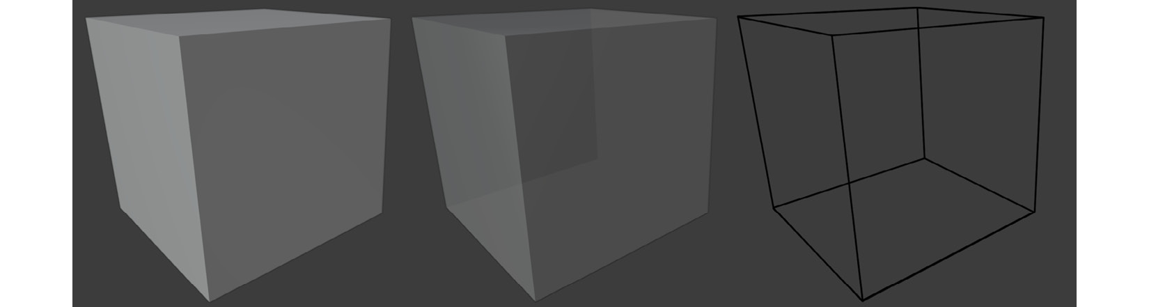
Figure 1.10 – Viewport Shading Modes – (A) Solid View Mode; (B) X-Ray View Mode; (C) Wireframe Viewport Shading Mode
Note
Solid View Mode is the default Viewport Shading Mode. In this mode, when you use the select box to select the components of a mesh, it will only select the components that are facing your current view (visible components). When you want to select mesh components on the other side of your current object (not visible in Solid View Mode), you need to activate either X-Ray View Mode or Wireframe Viewport Shading Mode.
The following shortcuts are used to toggle the View Mode options:
- Use Alt + Z to toggle X-Ray View Mode.
- Use Shift + Z to toggle Wireframe View Mode.
- Use Z to toggle the Shading Pie Menu, which contains the Solid, Wireframe and X-Ray Viewport shading modes.
You have just learned about the different Viewport Shading Modes and why these are essential when creating 3D assets. You need these to switch between Solid View Mode, X-Ray View Mode, and Wireframe Viewport Shading Mode to select mesh components on the non-visible side of your model.
This also concludes the Introducing Blender section. You now understand the user interface, Viewport navigation, how to select and deselect, and how to manipulate items with object gizmos.
In the next section, we will explore the 3D modeling tools that we will use in the next four chapters.
Exploring Blender's modeling tools
Let's take a look at the 3D modeling tools that we will use in our practical tutorials during the next four chapters. This section serves as a reference and is not meant to be a practical tutorial.
Note
In the Further reading section, you will find a link to download Additional Content Volume 1 – More Blender Tools and Modifiers.pdf. This is a document where I have covered a few more modeling tools and modifiers.
When using Blender's modeling tools, either click outside the mesh in the 3D Viewport to apply the current tool, or press Alt + A to deselect the active edit; this will also apply the tool.
Extrude region
This tool extrudes a face, edge, or vertex, thus increasing the volume of the mesh and adding new geometry to it.
To use this tool, switch to Edit Mode by pressing Tab. Then, either select the Extrude Region tool icon from the toolbar or use the E shortcut to extrude:

Figure 1.11 – (Left) Using the Extrude tool; (Right) The Extrude Region tool icon
If you're using the icon, left-click and drag the plus sign (or handle) to extrude the selected face/s out in a straight path.
Click and drag on the white circle to extrude in the screen space's direction (perpendicular to your current view).
Bevel
The Bevel tool is used to bevel your selected edge, vertex, or face. A bevel is used to smooth out edges and corners, as shown in the following screenshot.
To use this function, select the Bevel tool icon and the object's components that you wish to bevel. Then, click and drag on the yellow handle. The minimized Operator panel will appear in the bottom left of your 3D Viewport (below your mesh). It shows additional options when it is expanded (it is minimized by default). If you want to use a shortcut to bevel, press Ctrl + B:

Figure 1.12 – (Left) Applying a bevel with a varying number of segments; (Right) The Bevel tool icon
The default Bevel contains one segment, but after completing your first bevel, you can add more segments inside the Operator panel to make the bevel more rounded.
If you've used the shortcut (Ctrl + B) to bevel, you can use your mouse's scroll wheel to increase or decrease the number of segments, without needing to use the Operator panel. If you beveled using the Bevel tool icon from the toolbar, then you must use the Operator panel to add more segments.
Note
The Operator panel only appears once. If you left-click outside the Operator panel in the 3D Viewport, the Operator panel will disappear, so make sure you've made all the edits that you want to in the Operator panel before it closes.
Loop Cut
The Loop Cut tool is used to add an Edge Loop to your mesh (an encircling loop of edges that connects back to its starting point):

Figure 1.13 – (Left) Using the Loop Cut tool; (Right) The Loop Cut tool icon
To use this tool, select the Loop Cut tool icon from the toolbar, or use the Ctrl + R shortcut and follow these steps:
- Click on the area you wish to add the Edge Loop to. A yellow edge will appear indicating that your Edge Loop is still in Edit Mode.
- Click and drag the yellow Edge Loop to an area where you wish to place it.
- Press Alt + A to deselect and apply the Loop Cut.
Let's move on to the next tool now.
Inset Faces
The Inset Faces tool is similar to the Extrude tool, but all the faces it creates are on the surface of the selected face and do not change the mesh's surface shape. To use this tool, either press I on your keyboard or select the Inset Faces tool icon from the toolbar:

Figure 1.14 – (Left) Using the Inset Face tool; (Right) The Inset Faces tool icon
Merging faces, edges, and vertices
To collapse faces, edges, and vertices down to a single point, use the Merge function by pressing the M shortcut and choosing At Center:

Figure 1.15 – Merging vertices
Proportional Editing
Blender has a great function to modify mesh components with a soft fall-off. If you manipulate a component in your mesh with Proportional Editing enabled, the mesh components will move with a soft fall-off:

Figure 1.16 – (A) Selecting Proportional Editing; (B) Moving a vertex with Proportional Editing turned on; (C) Adjusting the fall-off
In the preceding screenshot, we can see what happens when we enable Proportional Editing in the Header bar. Alternatively, you can press O to toggle Proportional Editing on/off.
Immediately after your first modification, an Operator panel will appear in the bottom left of your 3D Viewport, with options to adjust the fall-off interactively.
In this section, you learned about different 3D modeling tools and Proportional Editing mode, which is used during 3D asset creation in Blender. These tools will come in very handy during our practical tutorial in Chapter 2, Modeling a Robot Drone Character.
Blender also has some other useful functions that give you more flexibility and options when you create 3D assets. These are called modifiers. We'll look at them in the next section.
Using modifiers in Blender
What is a modifier? Essentially, a modifier is like a mode (or function) that acts on a mesh's geometry, while allowing you to keep editing the geometry.
Modifiers are non-destructive, which means that you can toggle the modifier on or off at any time to revert to your original mesh. You can keep on modifying your mesh's geometry with the modeling tools since the modifier effect only acts on the mesh's geometry after you've made your edits.
Modifiers can act on their own or can be placed in a modifier stack in the Properties panel. When more than one modifier has been applied to the geometry, they can be re-arranged in any order to create a different result.
For example, if you put a Bevel Modifier on a 3D cube, and then you extrude some of the faces on that 3D cube, that Bevel Modifier will automatically bevel any new geometry's sharp edges.
In this section, you learned what modifiers are and what they are used for. In the next section, we will explore two of the modifiers that we will use for this book's practical tutorials. We will start with the Mirror modifier.
The Mirror modifier
Use the Mirror modifier to save time when constructing meshes that are symmetrical or have some symmetric parts on them.
With this modifier, you only need to model half of the symmetrical mesh; Blender will mirror it to the opposite side for you.
To use the Mirror modifier, follow these steps:
- Delete half of the mesh (the side that will be mirrored to).
- Make sure all the edges and vertices in the mirror center line of your mesh are in a straight line.
- Now that the mesh has been prepared, let's add the Mirror modifier. Find the spanner icon in the Properties panel. You will see a collapsed drop-down menu, as shown in the following screenshot:

Figure 1.17 – The Add Modifier drop-down menu from the Properties panel
- As soon as you click on Add Modifier in the drop-down menu, it will open and reveal all the modifiers that are available in Blender. Select Mirror from this list, as shown in the following screenshot:

Figure 1.18 – (A) Selecting the Mirror modifier; (B) The settings for the Mirror modifier
- Choose the correct axis to mirror your mesh. Then, turn on Clipping and Merge and change the amount to a number just high enough that it will merge the vertices in the center line.
In this section, you learned how to use the powerful Mirror modifier. You can choose to use it to act on your mesh while you do 3D modeling (to see the mirrored result in real time) or you can choose to apply the Mirror modifier after you complete a model. The choice is yours.
In the next section, we will explore the Subdivision Surface modifier.
Important
Before you use functions in Blender that add new geometry to your mesh (such as Remesh, Dyntopo, Subdivision Surface Modifier, or Multiresolution Modifier), you need to take your computer system's specifications (CPU, video card, and RAM) into account. The denser the geometry of the mesh becomes, the more system resources your computer will need.
Subdivision Surface modifier
This modifier adds a Subdivision Surface function (or mode) over your mesh's geometry to subdivide and smooth out the original shape while keeping the original mesh light in geometry (not having too many faces).
By doing this, you can keep editing the low-resolution mesh while seeing the smoothed shape update with the result. Like all modifiers, it can be toggled on or off:
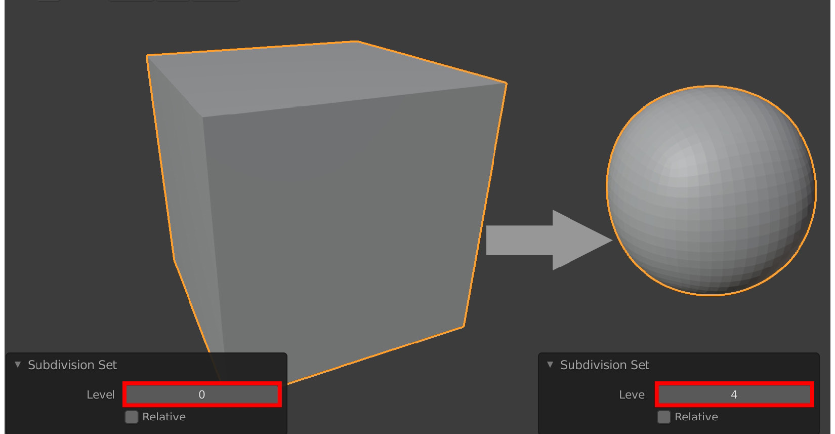
Figure 1.19 – Applying the Subdivision Surface modifier to a mesh
In the preceding screenshot, I used the Subdivision Surface modifier on a cube to turn the cube into a smooth-shaped sphere.
If you edit any of the original faces of the cube in Edit Mode (it will display as a Wireframe), the result of your mesh's edits will automatically be subdivided and smoothed by the Subdivision Surface modifier.
The keyboard shortcuts for this modifier are Ctrl + number (0 to 5).
The numbers 0 to 5 correspond to the subdivision level of the mesh in the modifier. You can switch between subdivision levels at any time.
The modifiers' Subdivision Set level can be found in the Operator panel, in the bottom left of the 3D Viewport. Using this menu is another way you can change the subdivision level of your mesh. To do so, click on the little arrows.
In this section, you learned how to use the Subdivision Surface modifier. With this, we have completed our introduction to the 3D modeling tools that are available in Blender.
In the next section, we will explore the other 3D asset creation method, known as 3D sculpting.
Using Blender's sculpting tools
You already understand the basic concepts of 3D sculpting. But now, let's explore how the 3D sculpting tools work in more detail. This section serves as a reference and is not meant to be practical.
Blender is excellent at 3D sculpting on meshes. When you select the Sculpture Workspace tab from the top bar, Blender automatically switches to Sculpture Mode, and the user interface changes to reflect this.
For this section, it is recommended that you use a graphics tablet and pressure-sensitive pen (also known as a stylus). That is because it makes sculpting more intuitive since we are primarily dealing with organic forms.
If you don't have a graphics tablet and stylus, don't worry – you can still follow along with the practical sculpture tutorial in Chapter 3, Let's Sculpt an Alien Plant!. Everything will still work, even if you are using a mouse instead of a stylus.
A good analogy of the digital sculpture experience would be to say that your stylus (or mouse) acts like a brush that deforms the digital clay (mesh). Depending on the tool you select, the brush affects the mesh differently.
You now know more about the Sculpture Workspace tab in Blender and the computer hardware that is used for 3D sculpting.
In the next section, we will explore the brush settings in detail.
Note
The sculpting brushes and tools that we will cover in this chapter are those that we will use in a tutorial in Chapter 3, Let's Sculpt an Alien Plant!. In the Further reading section, you will find a link to download Additional Content Volume 1 – More Blender Tools and Modifiers.pdf. This is a document in which I have covered more sculpting brushes and functions.
Brush settings
Because the basis of 3D sculpting is brush-based, we will first look at the brush settings.
The settings you should look at are Radius, Strength, and the positive or negative direction, which are indicated by + and - in the Header bar menu, respectively.
The default brush shortcuts are as follows:
- F for Radius (brush size).
- Shift + F for Strength.
- Hold Ctrl to toggle the negative (-) direction (inwards from the surface).
- Hold Shift to toggle the Smoothing Function while sculpting, as shown in Figure 1.24.This function works with the Draw brush, Draw Sharp brush and Inflate brush, which we will cover shortly. The Smoothing Function does not work on all brushes.
By default, the brush effect is in the positive (+) direction (pushes away from the surface):

Figure 1.20 – The Brush settings in the Header toolbar
You now have a good understanding of the brush settings that are used for 3D sculpting. In the next section, we will look at a function in Blender that is used to replace your geometry with new geometry.
Remesh
The Remesh function allows you to completely replace your existing mesh surface with a new, evenly spread-out mesh surface.
The reason you should use Remesh to replace your mesh's geometry is that during 3D sculpting, some of the geometry will become stretched (and give bad results for sculpting later). Remesh provides non-stretched geometry. Let's take a look at how we can use this function:
- Click on Remesh in the Header bar, as shown in the following screenshot:
- The density of this new mesh surface is dependent on the Voxel Size setting in the Remesh drop-down menu (the smaller the number, the denser the mesh). In the following screenshot, I have set Voxel Size to 0.1 for illustration purposes. The Voxel Size number you should use depends on what your computer system can handle, so adjust this number accordingly.
- Use the Ctrl + R shortcut to apply a remesh to your mesh. Alternatively, you can press the Remesh button at the bottom of the Remesh drop-down menu (highlighted in the following screenshot). Here, the mesh on the left is the original mesh, while the mesh on the right-hand side has been remeshed using a Voxel Size of 0.1:
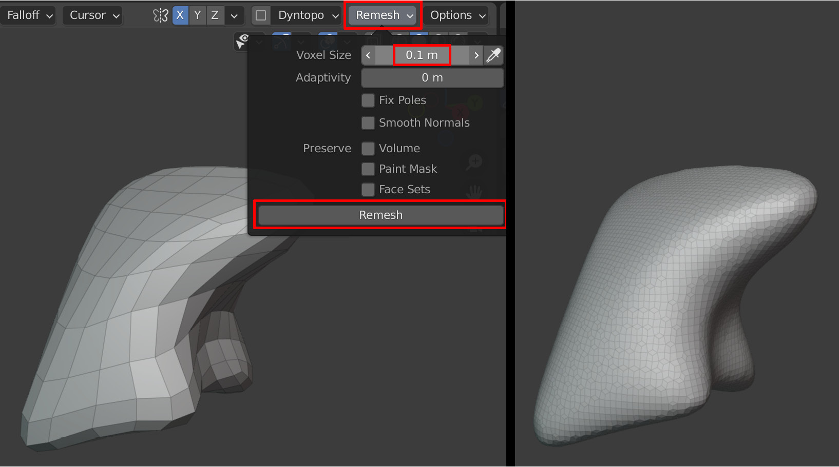
Figure 1.21 – (A) Applying Remesh to your mesh; (B) The result of using Remesh on your mesh
Figure 1.21, part A, shows a low geometric-density Sphere mesh that has been deformed. Because the face count is quite low, the mesh looks angular.
The Sphere mesh on the right-hand side has been remeshed with a higher density surface. This replaced the previous mesh surface with a new, evenly spaced-out mesh surface (the model on the right). Higher density surfaces are much better for 3D sculpting.
In this section, you learned how to use Remesh to replace stretched geometry or to provide denser geometry for your sculpts.
In the next section, we will explore how to use Blender's sculpting brushes.
Blender's sculpting brushes
In this section, we will go through all the 3D sculpting brushes that will be used in Chapter 3, Let's Sculpt an Alien Plant!.
Let's start with the Draw brush.
Draw brush
This is the default brush that is selected when you launch the Sculpture Workspace. This brush has a soft fall-off. Negative mode (-) pushes in the surface instead of pulling it out, as shown on the right-hand side of the following screenshot. To use this tool, either press X on your keyboard or select the Draw brush icon from the toolbar:

Figure 1.22 – (Left) Using the Draw brush; (Right) The Draw brush icon
Draw Sharp brush
This is used to carve sharp cuts. This brush has a sharp fall-off. Negative mode (-) pulls up a sharp crease on the surface instead of carving it in, as shown on the right-hand side of the following screenshot. To use this tool, either press Spacebar + 1 on your keyboard or select the Draw Sharp icon from the toolbar:

Figure 1.23 – (Left) Using the Draw Sharp brush; (Right) The Draw Sharp icon
The Brush Smoothing function
The Draw brush, Draw Sharp brush, and Inflate brush all have a smoothing function when you hold Shift while doing 3D sculpting:

Figure 1.24 – Using the Brush Smoothing function
Inflate brush
This brush inflates the surface or deflates it in negative (-) mode. To use this tool, either press I on your keyboard or select the Inflate brush icon from the toolbar:
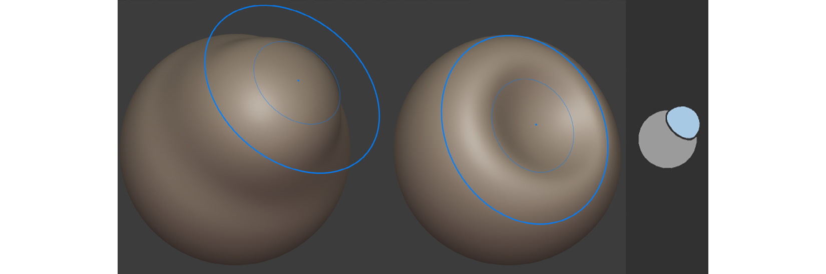
Figure 1.25 – (Left) Using the Inflate brush; (Right) The Inflate brush icon
Mask brush
You can paint a mask on an area on the surface of a mesh to block or limit the effect of manipulation of that area (by other brushes). To use this tool, press M on your keyboard or select the Mask brush icon from the toolbar. Holding Ctrl while painting will remove the masked area under the brush:
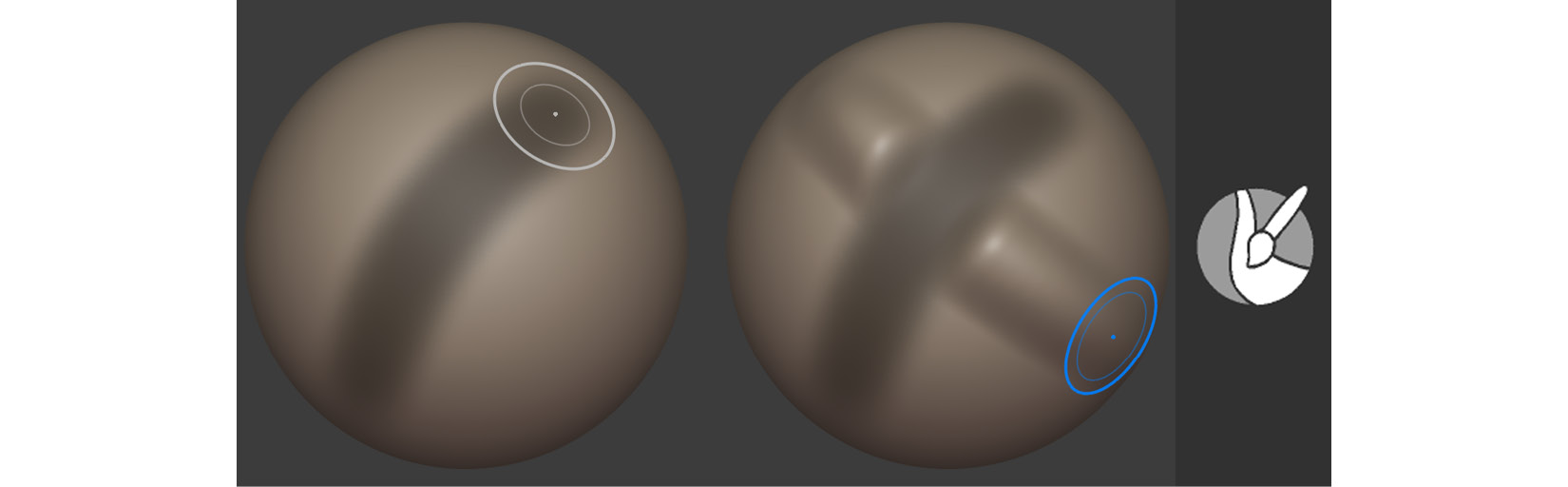
Figure 1.26 – (Left) (A) Painting a mask on a mesh; (B) The masking effect in action, demonstrated by brushing over the masked area with the Draw brush; (Right) The Mask brush icon
Pressing A brings up the Masking Pie menu, which contains many options for your mask, such as Sharpen Mask, Grow Mask, Shrink Mask, Decrease Contrast, Invert Mask, and Clear Mask.
In this section, you learned about the different brushes that will be used in the tutorial for Chapter 3, Let's Sculpt an Alien Plant!.
However, there are some more sculpting functions in the sculpting toolbar. We will explore these functions in the next section.
Other sculpting tools
There are two sculpting functions that we will use the most during our tutorial.
These aren't brushes; they act more like functions or modes. We'll start by looking at the Line Project tool.
Line Project tool
This tool is used to flatten an area of your mesh. To use it, you draw a guideline that tells the tool in which direction it should flatten a part of your mesh.
The shadowed side will be flattened toward the clear side, as shown in the following screenshot:

Figure 1.27 – (Left) (A) Drawing the guideline; (B) Observing the flattened mesh area; (C) Another view of the mesh; (Right) The Line Project icon
You now know how to flatten an area of a mesh if you need to. This function will come in very handy in Chapter 3, Let's Sculpt an Alien Plant!.
Next, let's look at another versatile sculpting tool – the Mesh Filter tool.
Mesh Filter tool
This tool applies an effect of your choice evenly across your entire mesh at the same time.
In the following screenshot, I used the Mesh Filter tool to apply a Noise effect to a mesh's surface. To copy what I have done on my mesh, select the mesh filter icon from the toolbar. In the drop-down menu that opens, select Random, as shown in the following screenshot:

Figure 1.28 – (Left) The mesh filter drop-down menu in the Header bar; (Right) (A) A subdivided sphere on the left; (B) The same sphere with a Noise effect applied
The following screenshot shows the Mesh Filter icon:

Figure 1.29 – The Mesh Filter icon
You have just learned how to use the Mesh Filter tool to quickly add an effect (of your choosing from the drop-down menu) to your mesh.
Congratulations! You've completed all the sections in this chapter. With this knowledge, you can start the next chapter.
Summary
In this chapter, you learned about the basics of 3D modeling and sculpting. You've also gained a thorough understanding of the most used 3D modeling and sculpting tools, as well as some of the modifiers that we will use in the practical exercises.
Additionally, this chapter serves as a handy reference for the hands-on tutorials in Chapter 2, Modeling a Robot Drone Character, Chapter 3, Let's Sculpt an Alien Plant!, and Chapter 4, UV Maps and Texture Baking.
In the upcoming chapters, we will put some of the knowledge that you've gained about 3D modeling and sculpting to good use. Let's have a brief look at what's ahead.
In the next chapter, you will jump right into a mechanical Robot Drone modeling exercise for your 3D movie. This exercise will provide ample practice for sharpening your 3D modeling skills.
In Chapter 3, Let's Sculpt an Alien Plant!, you will sculpt an organic-shaped Alien Plant, which will provide plenty of 3D sculpting practice.
See you in the next chapter!
Further reading
- Additional Content Volume 1 – More Blender tools and Modifiers.pdf: https://github.com/PacktPublishing/Unreal-Engine-5-Character-Creation-Animation-and-Cinematics/tree/main/Chapter01.