
Chapter 11: Alien Plant Joint Setup in Blender
In Chapter 3, Let's Sculpt an Alien Plant, you learned how to model and texture the Alien Plant. Now it's time for us to prepare it for animation and to finally give it some life. Most 3D software offers many different ways to animate models. Among these, two are the most common.
The first way to animate a 3D model is by directly moving, rotating, and/or scaling it. This method is best suited for simple animations involving a rigid model. The second method uses a skeleton (sometimes called an armature) that is linked to the structure of the model.
Unless it's a very simple animation, the animation is normally better done using skeletons. The skeletons of 3D models are made up of bones. Just as bones in a real skeleton define the overall shape and mobility of a person, the bones of a 3D model skeleton correspond to the underlying structure, therefore defining which parts of the model can move in animations.
You will notice that some 3D software refers to bones as joints. This may seem confusing at first but think of them as joints in a real skeleton; by the end of this chapter, you will see that it is just another way of looking at the same thing.
In this chapter, we will cover the following:
- Preparing our model for the skeleton
- Parent/child hierarchies in 3D software
- Creating a skeleton for the Alien Plant
Technical requirements
You need to have Blender installed for free from https://www.blender.org/ (at the time of writing). The Blender version in this chapter is 3.1.2, but some older and newer versions will also work.
You also need to have a basic understanding of how to navigate the 3D user interface. If you skipped ahead, this was covered in Chapter 1, An Introduction to Blender's 3D Modeling and Sculpting Tools. If you want further in-depth tutorials on how to use Blender, https://www.blender.org/support/tutorials/ is a great resource.
The files related to this chapter are placed at https://github.com/PacktPublishing/Unreal-Engine-5-Character-Creation-Animation-and-Cinematics/tree/main/Chapter11
Preparing our 3D model for the skeleton
Like many things in life, it's all about preparation. Before we can do anything, we need to prepare our 3D model to set us up for success. Here, we will learn how to import and prepare our model for the best results. This is also the best practice way if you were to work in a team or a studio with other artists.
Importing the Alien Plant into Blender
The model of the Alien Plant can be imported into Blender via the FBX format. This is a universal file format used by most 3D software packages, including UE5, Blender, Maya, and 3D Studio Max. FBX has limitations and will not contain some program-specific things. It is mainly used to transfer 3D assets from one 3D program to another for further work.
To import your Alien Plant model, simply follow these steps:
- Open Blender and go to the top-left corner and click on File | Import | FBX (.fbx), as shown in Figure 11.1:
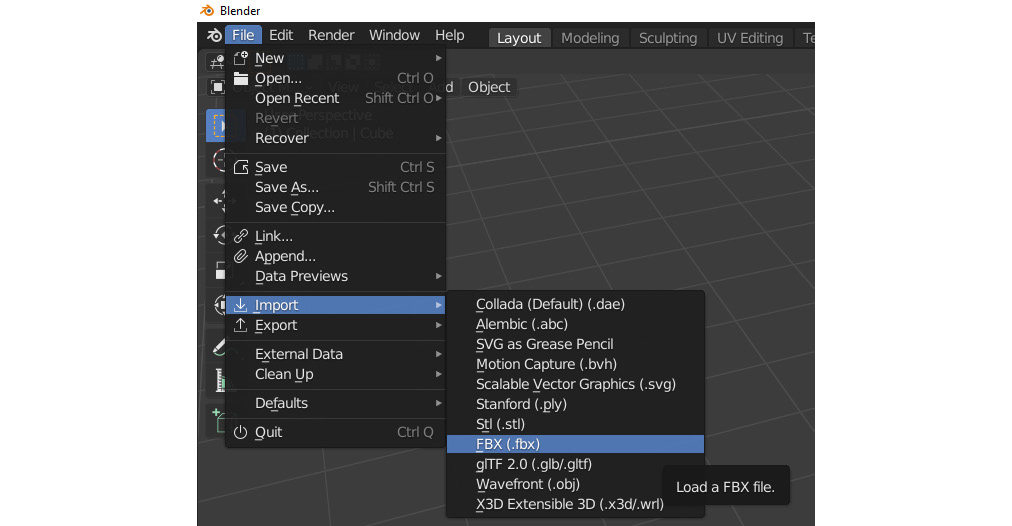
Figure 11.1 – Importing an FBX file into Blender
- After clicking on FBX (.fbx), the following dialog box will appear, as shown in Figure 11.2. Use it to navigate to your previously saved FBX model file for your Alien Plant or the one included with the book files. The FBX file can also be downloaded here: https://github.com/PacktPublishing/Unreal-Engine-5-Character-Creation-Animation-and-Cinematics/blob/main/Chapter11/AlienPlant.fbx. Once you locate the file, click Import FBX in the bottom-right corner:
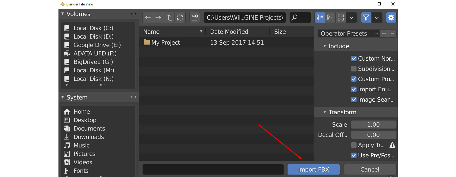
Figure 11.2 – Importing an FBX file into Blender file navigation
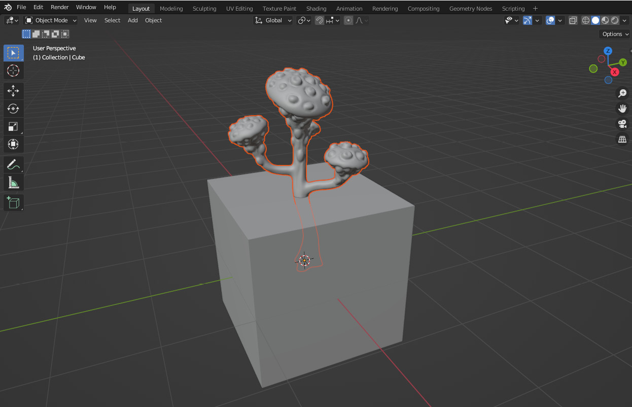
Figure 11.3 – The Alien Plant FBX 3D model imported into Blender
Best practice when importing your model
Before moving on to the next step, and as a general note, it is best practice to make sure that whatever the model is you want to create a skeleton for, the model is positioned as perfectly as possible in the middle of the 3D scene, also commonly referred to as the origin of the scene.
It's also better if the 3D model is facing straight as perfectly as possible in one of the 3D scene axes (X, Y, and Z directions) while the bottom of the model is on the ground. For example, the Unreal Engine Mannequin model would be positioned as shown in Figure 11.4. His feet are on the ground, perfectly at the origin, and he is facing directly on the Y axis:
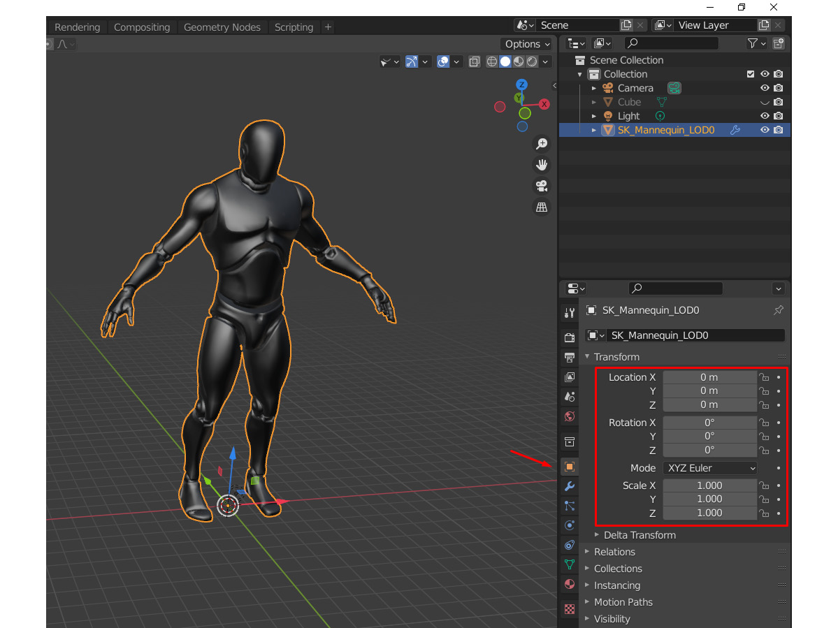
Figure 11.4 – Model positioning at the origin of the 3D scene
You will notice that in Blender, the feet of the character are on the floor (0 height) and where the green and red lines cross is the origin of the scene (0, 0, 0 coordinates). Left-clicking on any model, in this case, the Mannequin model, on the right side of the screen, you can see the Transform tab. If you don't see it, click on the Object Properties icon indicated by the red arrow. Notice that Location and Rotation are set to 0, 0, and 0, and Scale is set to 1, 1, and 1. You can change those numbers by clicking on them and changing them.
It's best practice (and recommended) that you set those values as such to move your model's local pivot to the world origin. However, if your model is then sticking through the floor, or has the wrong orientation or wrong scale, you can fix that easily. Your model's scale should also be correct before you create a skeleton for it.
Positioning and scaling the Alien Plant
Before moving on to the creation of the skeleton, let's look at the Alien plant again. Let's examine whether it is positioned and scaled correctly. The model is on the floor and since it has irregular branches, it is facing the best it can in a flat forward direction. However, how about the scale? Let's check. This can be done in several ways.
A less accurate way is to import a human character (such as the UE Mannequin) into the scene and scale the other 3D objects to match the relative human scale visually. I often do this just to double-check that things look in proportion to my correctly-scaled player characters.
The easiest and most accurate way to check the scale of an object in Blender is with the Measure Tool, as shown in Figure 11.5:
- Place the viewport in the Right Orthographic view so the Alien Plant model can be measured more easily from the flat side view.
- On the toolbar on the left, select the Measure Tool, marked with X.
- Left-click and hold the mouse button at the base of the Alien Plant model (A) and drag it to the top of the Plant. Release the mouse button at B to complete the Measure Tool guide:
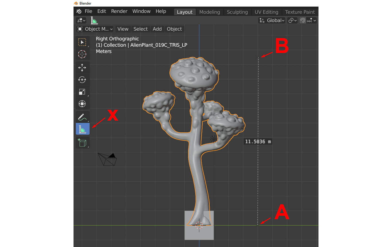
Figure 11.5 – Alien Plant position and scale in Blender
You can now see that this particular Alien Plant model is about 11.5 meters tall. Your custom-created plant might be of a different scale, so this is just for illustration. For our final scene, we want it to be just a bit taller than a human, so about 2.2 meters to 2.4 meters, as shown in Figure 11.6.
- Repeat the previous steps to create another Measure Object, but this time drag it so it's about 2.4 meters tall as a guide.
- Use the Scale tool to scale the Alien Plant to that guide height. The Measure Tool will disappear while using the scaling tool, but you can switch between the Scale tool and the Measure Tool for reference:
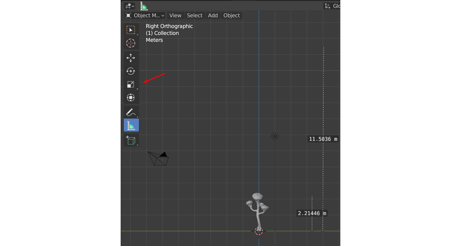
Figure 11.6 – Scaling the Alien Plant with the Scale tool
Tool Note
If you still have the cube in the scene that opens with a standard Blender scene, you can delete it at this point, since it's not needed and will most probably only get in the way.
- You can then reframe your scene to focus on the newly resized plant by using View | Frame Selected or the period (.) key on the number pad (depending on your keyboard shortcut setup), as shown in Figure 11.7:
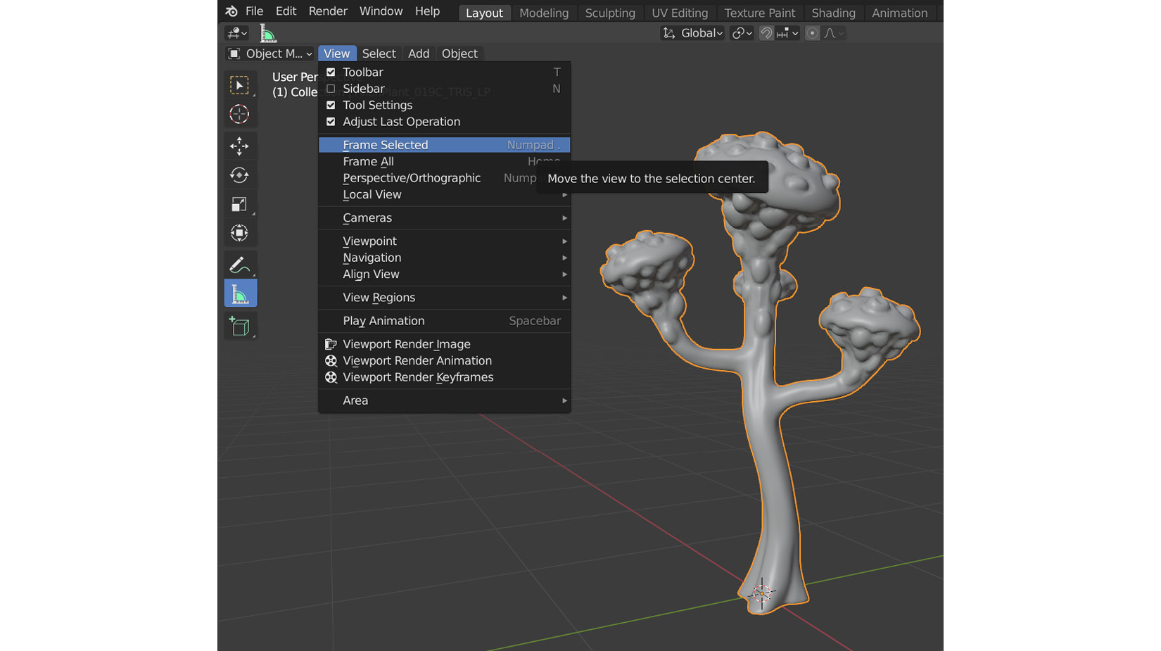
Figure 11.7 – Framing the selected Alien Plant in the Blender viewport
- Finally, in the top-right corner, click on Object | Apply | All Transforms. This should reset all the transform values of the 3D model to the default 0, 0, 0 and 1, 1, 1 for Scale, without affecting the actual size of the 3D model, as shown in Figure 11.8:
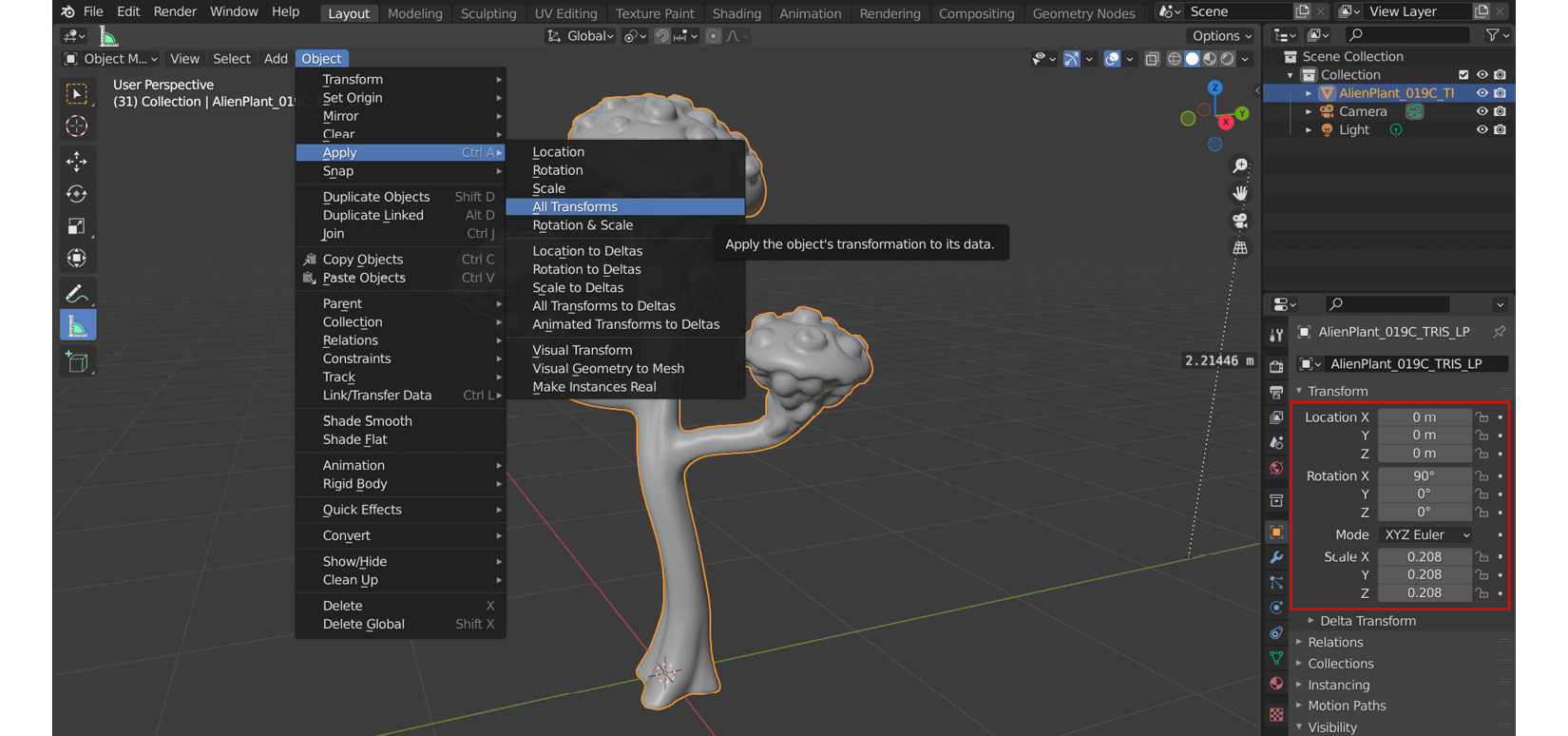
Figure 11.8 – Applying transforms to reset to the default values
Important Note
The reason we do this is that it makes the creation of the skeleton, skinning, and rigging much easier. It keeps things nice and tidy and is generally just good practice if you work with other artists in a team. Having a skinned model with non-default scale and transform values might be confusing later.
Also, once a character is skinned, it becomes very hard to scale the model afterward in some 3D packages. In Unreal Engine, it's not such a big problem, but it's still better to have the correct scale before skinning in case you need to use other 3D packages in your pipeline later.
You've learned how to import a .fbx model and check the world position and scale. After making sure your self-modeled Alien Plant is positioned optimally in the 3D scene, it's time to move on to the next step. Alternatively, import the Alien Plant model provided in the book materials: https://github.com/PacktPublishing/Unreal-Engine-5-Character-Creation-Animation-and-Cinematics/blob/main/Chapter11/AlienPlant.fbx.
Next, we will learn about parent/child relationships in 3D software.
Parent/child hierarchies in 3D software
Before we start creating the skeleton itself, I just want to take a moment to explain the parent and child concepts, also called the hierarchy in 3D programs.
Parent/child hierarchies in 3D software are explained with the simple concept that a child always follows the parent as they walk around when the parent is holding the hand of the child.
However, if the child pulls away, the parent doesn't follow the child. Now, imagine a family: the parent and four children, Child A, Child B, Child C, and Child D. They are connected in the following way, as shown in Figure 11.9:
- If we now select the parent, all the children will move with the parent since it is at the top of the hierarchy, as shown in Figure 11.9.
- In the same way that Child A and Child B are the children of the parent, Child B is the parent of Child C and Child D. If we only select and move Child B, then Child C and Child D would follow and the rest would stay where they are, as shown in Figure 11.9.
- Child A, Child C, and Child D are at the end of the parent/child hierarchy chain, and if you select and move them, the parent and Child B will stay in the same place, as shown in Figure 11.9:
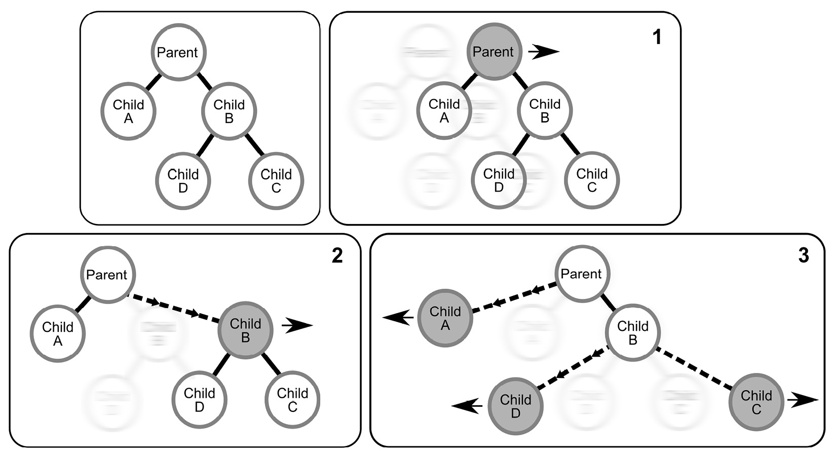
Figure 11.9 – How parent/child hierarchies work
Skeleton hierarchies work in the same way as these parent/child relationships. Figure 11.10 shows an example of the standard UE Mannequin hand skeleton in Maya. I chose to show it in Maya because it is visually a bit easier to understand the relationship between the joints.
The little circles are the actual joint pivots. The elongated triangular lines are the parent/child linkages, with the thicker part of the triangle on the parent side and getting thinner as it points to the child. Most 3D software displays it in a similar way:

Figure 11.10 – Standard arm skeleton in 3D software
They work the same way in Blender, but Blender displays the parenting a bit differently at times and it can be visually a bit more confusing at first glance when a custom parenting is created. However, it's nothing to worry about, as you will see in the rest of the chapter as we make our skeleton.
Now that you understand child/parent hierarchies, we can move on to making the skeleton.
Creating a skeleton for the Alien Plant
Blender is just one of the many 3D software packages that can be used to create skeletons and joints for your models or characters. Most use roughly the same kind of workflow, with some small differences. In Blender, skeletons and their bones are created under a grouping called Armature, named after the wire supports used for stop motion animation and inside some sculptures. Blender might not refer to them as skeletons but in the industry, more generally, people just call them skeletons.
Everything is now ready to create our Alien Plant skeleton. Blender has some oddities in how it displays the hierarchy in the viewport with parenting, but in reality, it is the same as most 3D packages in structure.
Creating the skeleton
As we mentioned earlier in the chapter, in Blender, skeletons are grouped under the name of Armature. Now, let's learn how to make one for our plant:
- At the top left of the standard Blender interface, click on Add | Armature, as shown in Figure 11.11:
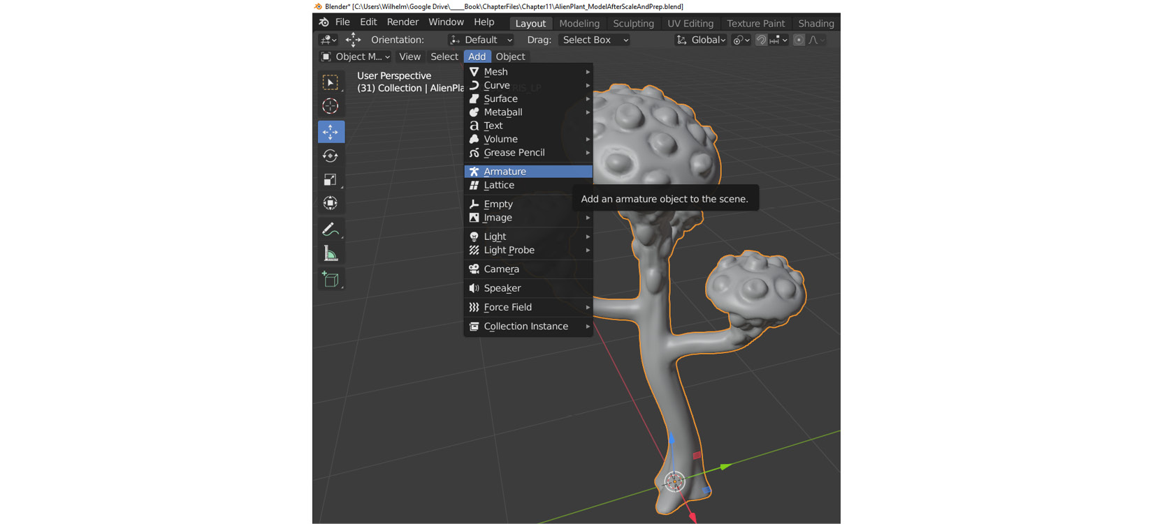
Figure 11.11 – Adding an armature in Blender
At the bottom left of the screen, an Add Armature menu will appear. Here, we can check the unit scale. If needed, change this to 1 m so the bones are bigger and more visible on the screen, as shown in Figure 11.12:

Figure 11.12 – Setting the bone size in Blender
- With the newly created armature still selected, on the bottom right of the screen, click on the green stick figure tab on the Properties tab (Object Data Properties), expand Viewport Display, then click the checkbox to toggle In Front and Axes on, as shown in Figure 11.13:

Figure 11.13 – Bone Viewport Display settings
This will display the skeleton bones over the 3D models so it's easier to work with. Axes will display the axes (local orientation) of the bones. In some cases, this is very helpful to see this in the viewport, so it's a good habit to switch them on.
You can see your Armature group and Scene Collection in the viewport, as shown in Figure 11.14.
Note
If the armature doesn't appear at the origin of the scene, you probably need to reset the 3D cursor back to the world origin. The armature will be created on the cursor like other objects. You do this by using the drop-down menu at the top left of the screen: Object | Snap | Cursor To World Origin.
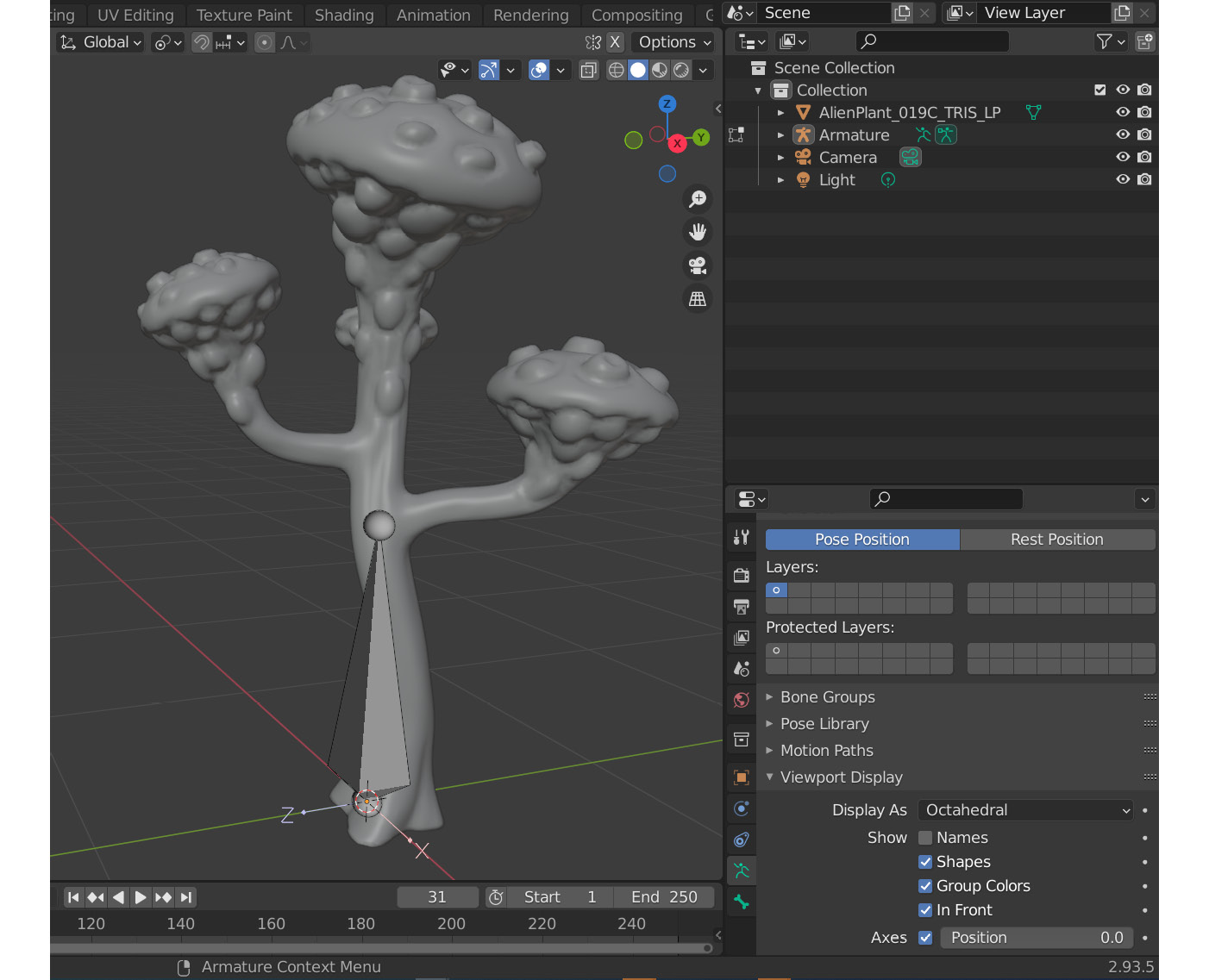
Figure 11.14 – Bone Viewport Display in Blender
- If you expand the hierarchy by clicking on the little triangle, you will see that our armature currently only has one bone, as shown in Figure 11.15. This is also a good place to check on your parent/child hierarchy, as we will see later:

Figure 11.15 – Bone hierarchy display in Blender Scene Collection
Next, I like to keep the first bone, or what we call the root bone, at the origin of the scene. This bone will be a good overall parent for our entire skeleton at the origin of the 3D scene later in UE, but the bone is visually a bit too big, so let's scale it down.
- Put Blender in Edit Mode. Now, all the regular editing tools are available to use on the bones, as shown in Figure 11.16:
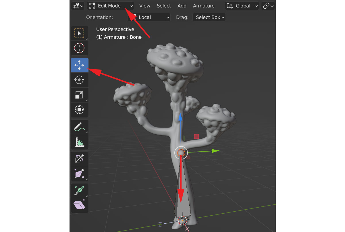
Figure 11.16 – Editing bones in Blender with Edit Mode and the Scale tool
- Select the Move tool, then select the small sphere at the end of the bone in the viewport. Move it downward on the Z axis. You will see that the bone will scale down as you move the little sphere down. Move it till it's not visually so much in the way, as shown in Figure 11.17:
.
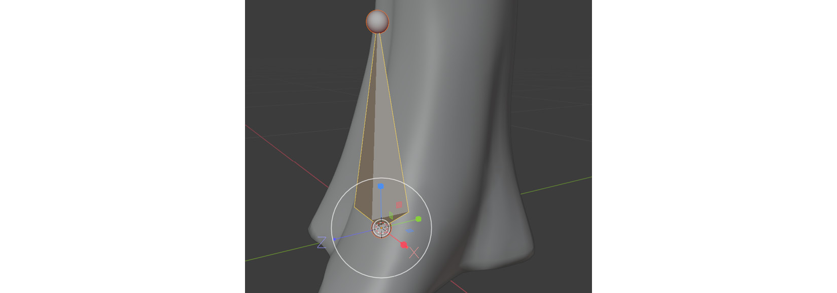
Figure 11.17 – Editing bones scale in Blender result
- Now, select the bone itself, and click on Armature | Duplicate to create another copy of the bone, as shown in Figure 11.18. The new bone will move with the mouse till you click again. Don't worry if it's in the wrong location after this step:
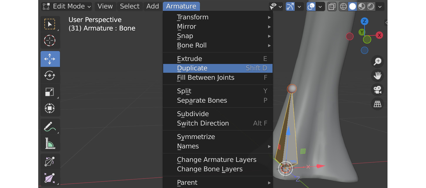
Figure 11.18 – Duplicating and editing bones in Blender
- You can position it afterward, as shown in Figure 11.19, above the previous bone, but roughly in the middle of the plant's stem. You will also notice that we now have one extra bone in the Scene Collection hierarchy:
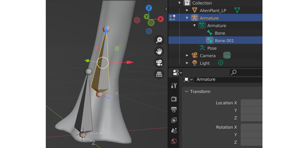
Figure 11.19 – Moving and editing the duplicated bone
- By double-clicking on the name of the bones in the Scene Collection, rename them as RootBone and StemBone01, as shown in Figure 11.20:

Figure 11.20 – Renaming bones in Blender
Creating a parent/child relationship
However, there's a problem. We want RootBone to be the overall parent of our entire skeleton so all the other bones follow RootBone. At the moment, the bone hierarchy itself is what we call flat. Both RootBone and StemBone01 are on the same level in the hierarchy, so neither will follow the other. Let's fix that:
- While still in Edit Mode, select StemBone01 first in the viewport. Hold Shift on the keyboard and then select RootBone second. The order of selection is important since the last selected object will be given the role of the parent. In the top-left corner, select Armature | Parent | Make, as shown in Figure 11.21:
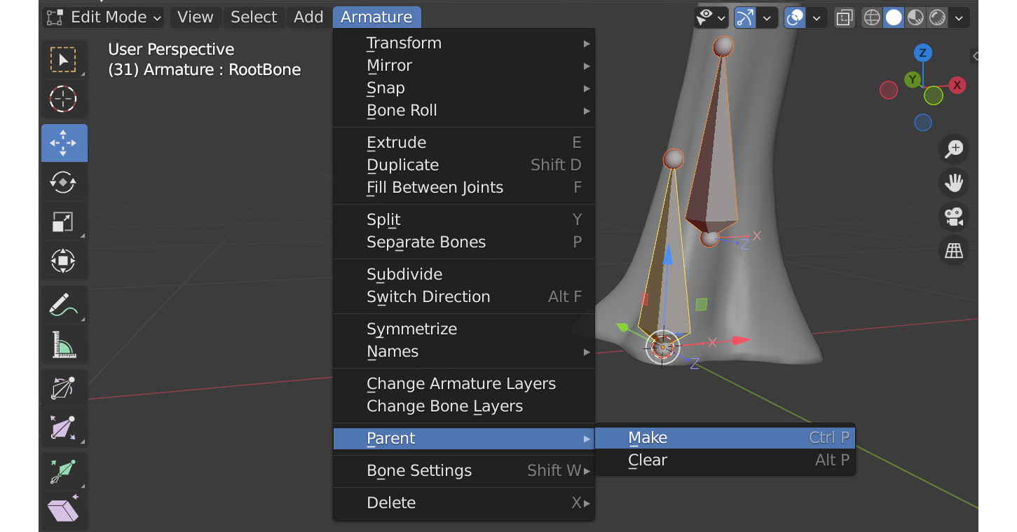
Figure 11.21 – Editing the bones parenting in Blender
- A second menu will appear. Choose Keep Offset, as shown in Figure 11.22:

Figure 11.22 – Keep Offset menu in bones parenting
- If you look at Scene Collection again, it might seem like StemBone01 disappeared, but if you click on the little triangle, the hierarchy will expand and, as you can see, StemBone01 is now the child of RootBone, as shown in Figure 11.23:
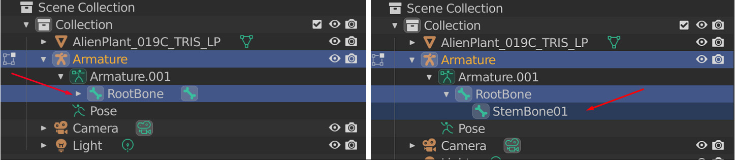
Figure 11.23 – Bones hierarchy displayed in Scene Collection
In the viewport, the parenting is indicated with a dotted line, as shown in Figure 11.24:
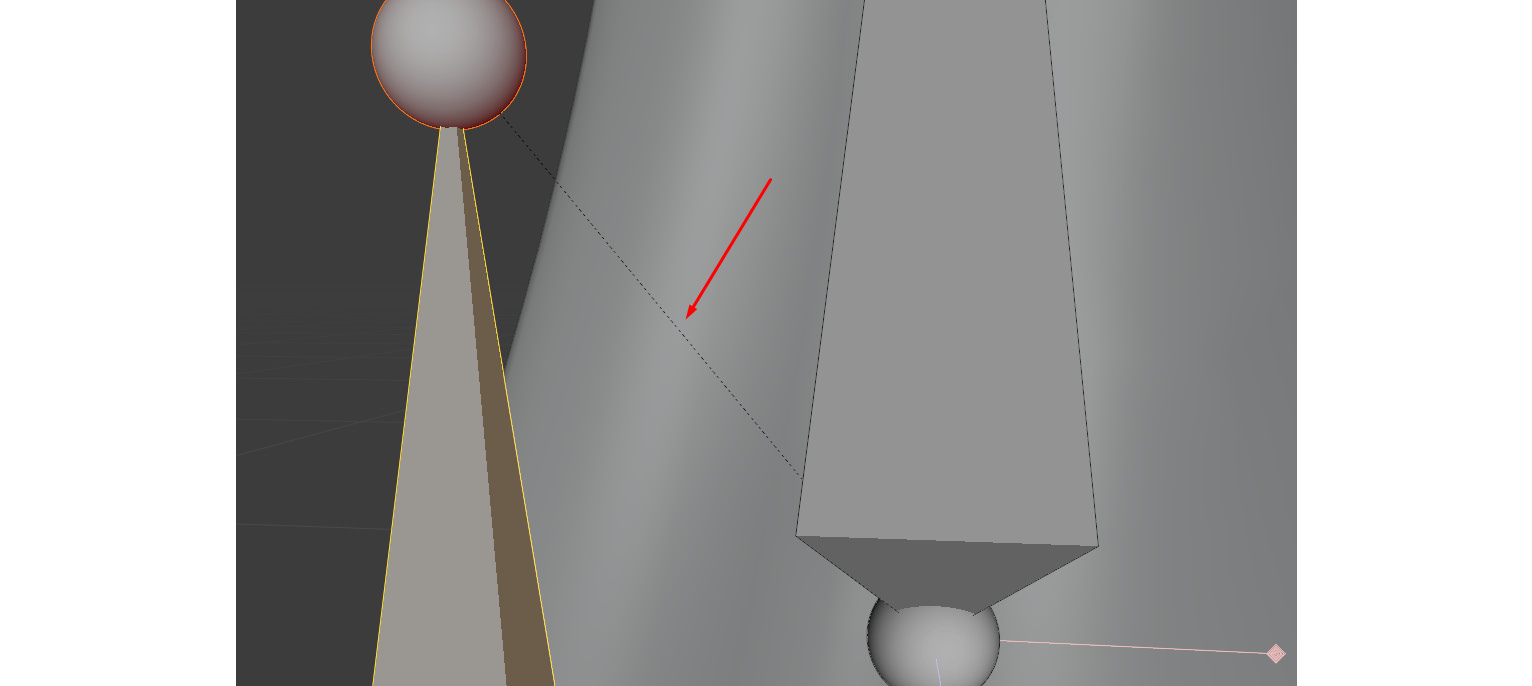
Figure 11.24 – Bones hierarchy displayed in the Blender viewport
We have now learned how to do custom parenting if needed. Now, let's learn a way to make a longer joint chain quickly.
Making a long joint chain for the main stem
We now need a longer skeleton parent/child chain to do the main stem of the Alien Plant. Instead of repeating the previous steps one by one till we have a long enough chain from the bottom of the main stem to the top, we will use the special Extrude function for bones:
- The next step is better done in the Right Orthographic view instead of in perspective. Simply select the little sphere at the top of the bone of StemBone01 and then click Armature | Extrude. The bone will extrude till we click the mouse again. There's also a keyboard shortcut in the default Blender settings by just pressing E, as shown in Figure 11.25:
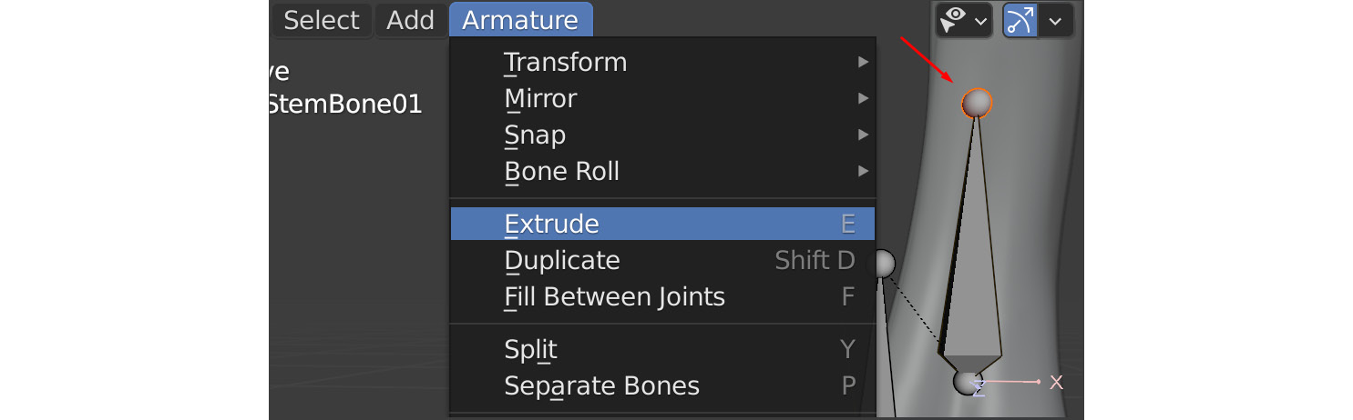
Figure 11.25 – Creating more bones by extruding them
- Repeat this step until your armature resembles that of Figure 11.26. Notice that I created a bone on each split of the branches to link their bone chains up in the later steps. I marked these with arrows in Figure 11.26:

Figure 11.26 – Extruded bones result and bones for forked branches
- Now, switch to the Back Orthographic view. Because we extruded in the Right Orthographic view, it created the extrude on a flat plane relative to that view. This is what we wanted; now, we just need to adjust it from the back (the side of the Alien Plant) view.
The easiest way to do this is to select and move the little spheres at the top of the bones. You can also select the main bone and move it if needed, but it behaves differently. Feel free to experiment as shown in Figure 11.27:
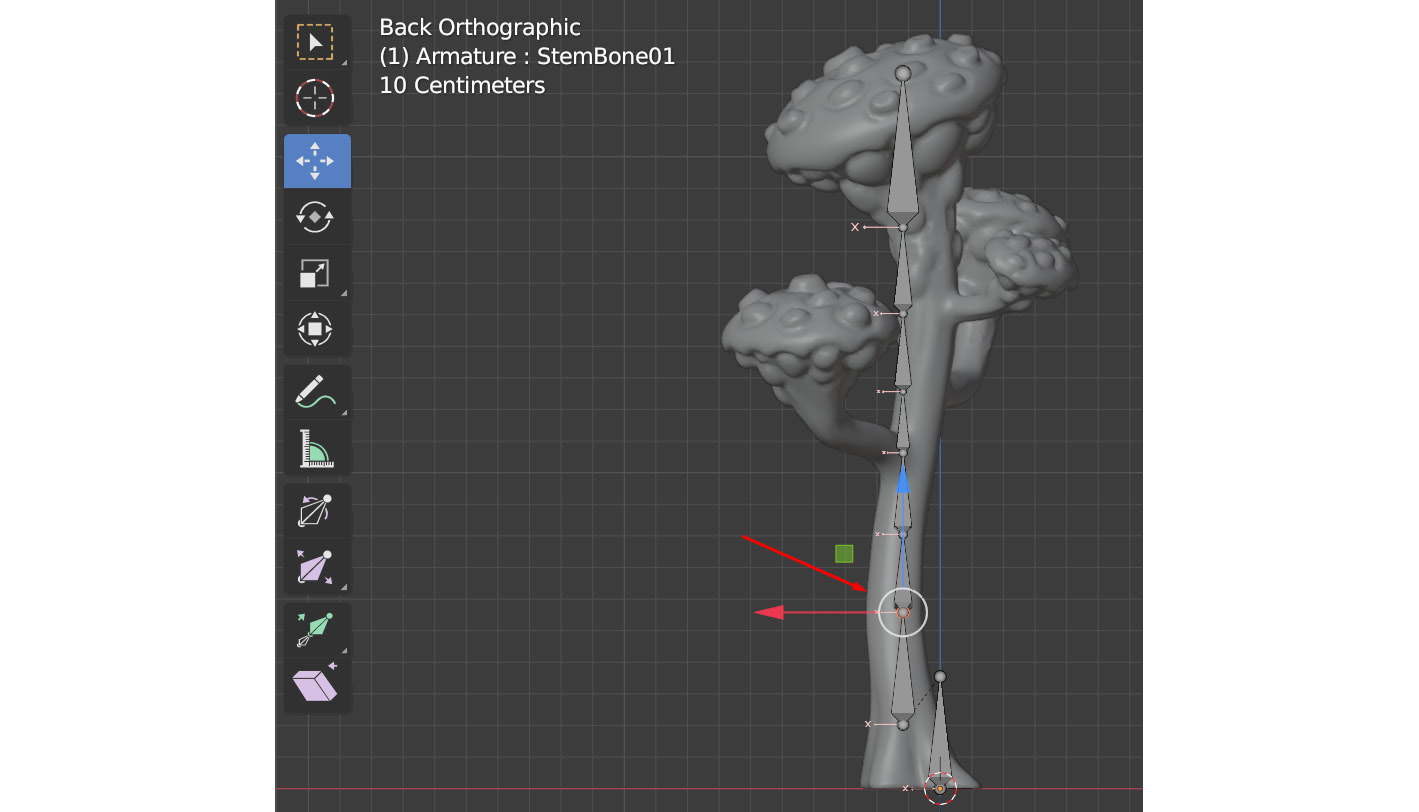
Figure 11.27 – Adjusting the bone positions
Important Note
The aim of creating this kind of skeleton is for the bones to run down the middle of the main stem at regular enough intervals so we get nice deformations once it's skinned. Once you have done a few, you will start to get a feel of where the best places are to place the bones in future projects.
After moving the bones according to the stem profile, it should look something like Figure 11.28:
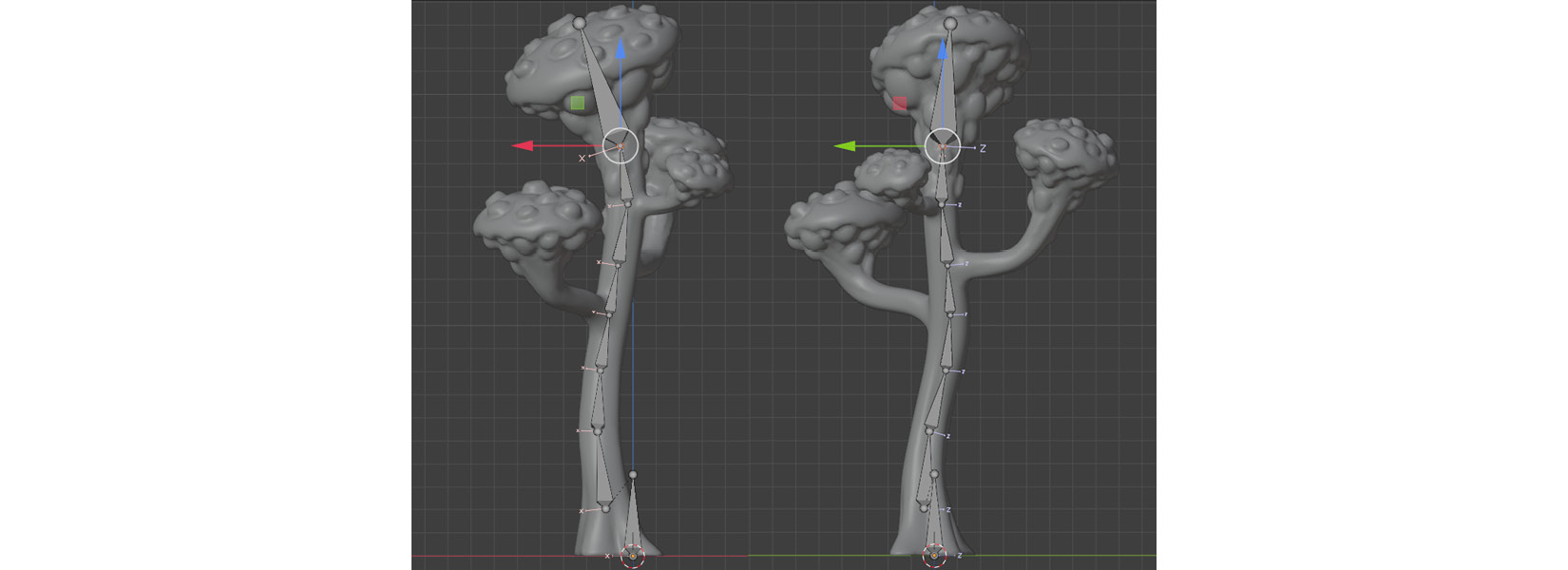
Figure 11.28 – Results after moving the bones, back and side view
Make sure to navigate around the 3D model to check that the bones are well-positioned inside the main stem. If not, make small adjustments till you're happy with the placement.
We now have a full bone chain for the main stem of our Alien Plant. Next, we will explore how to create additional bones for the branches as part of the same skeleton.
Making the skeleton for the branches
To make the branches, we're going to use Extrude and Subdivide. The latter is another one of the techniques available and is very useful to make quick joint chains:
- First, select one of the little spheres where a branch would fork off and extrude it like before. This time, you can see that it forks the joint, as shown in Figure 11.29:
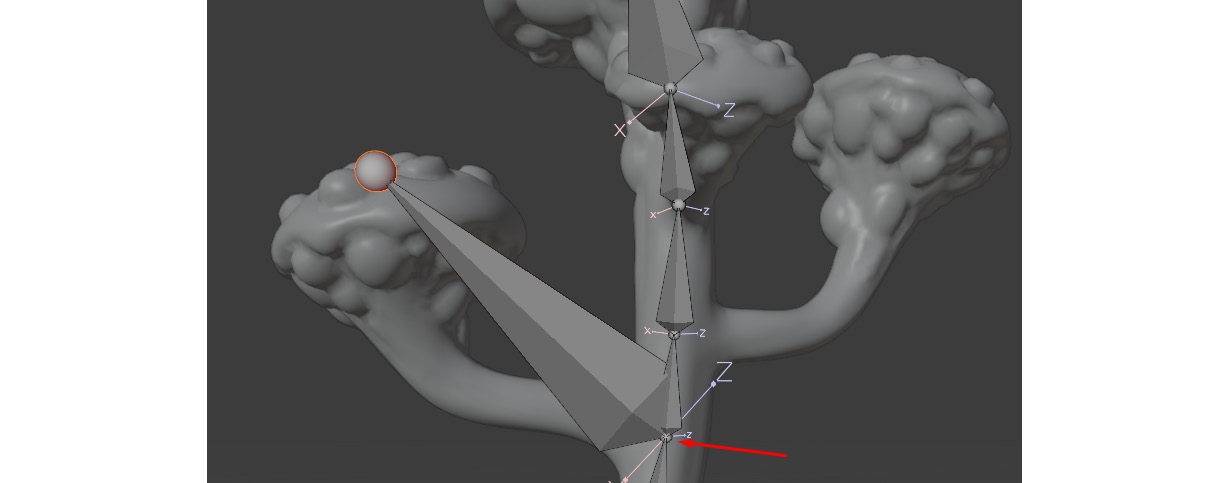
Figure 11.29 – Extruding the branch bone
- Position the end of the bone to the top and middle of the bulb, as shown in Figure 11.30. Make sure to navigate around the plant in your perspective view to check that it's in the right position before the next step:
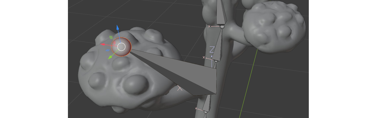
Figure 11.30 – Checking the bone position
- Use the Scene Collection menu to select the branching base bone again so that it's highlighted, and then click Armature | Subdivide, as shown in Figure 11.31:
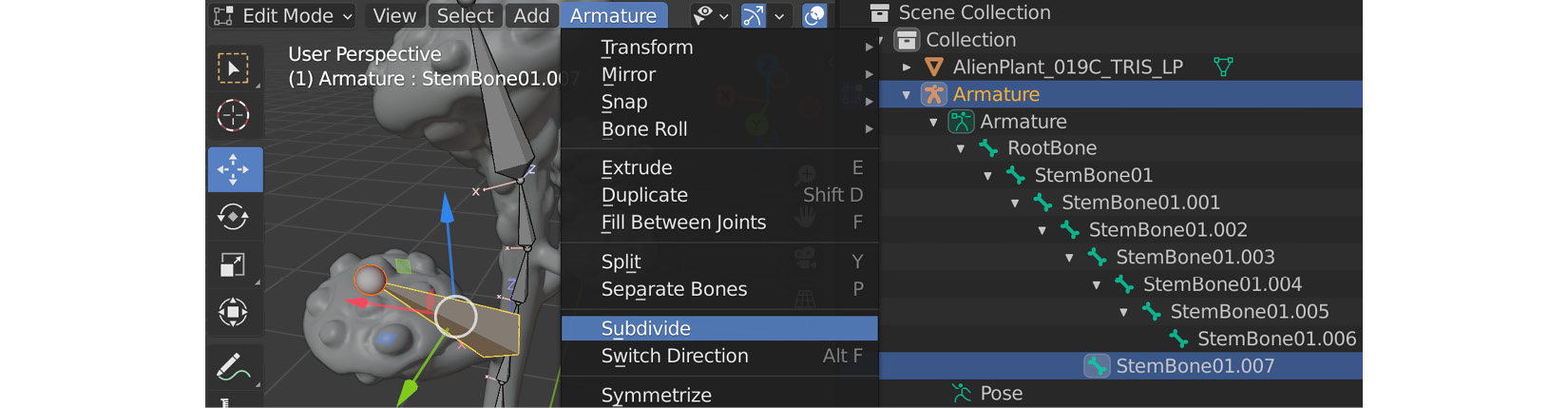
Figure 11.31 – Subdividing a bone
This will subdivide the bone into two equal pieces, as shown in Figure 11.32:
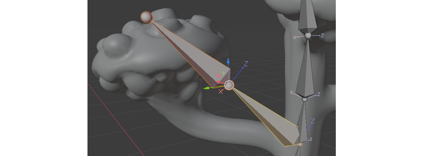
Figure 11.32 – Subdividing a bone results
- Position this new joint (little sphere) at the base of the bulb while making sure to navigate around the object to check that the position is correct from all angles like before, as shown in Figure 11.33:
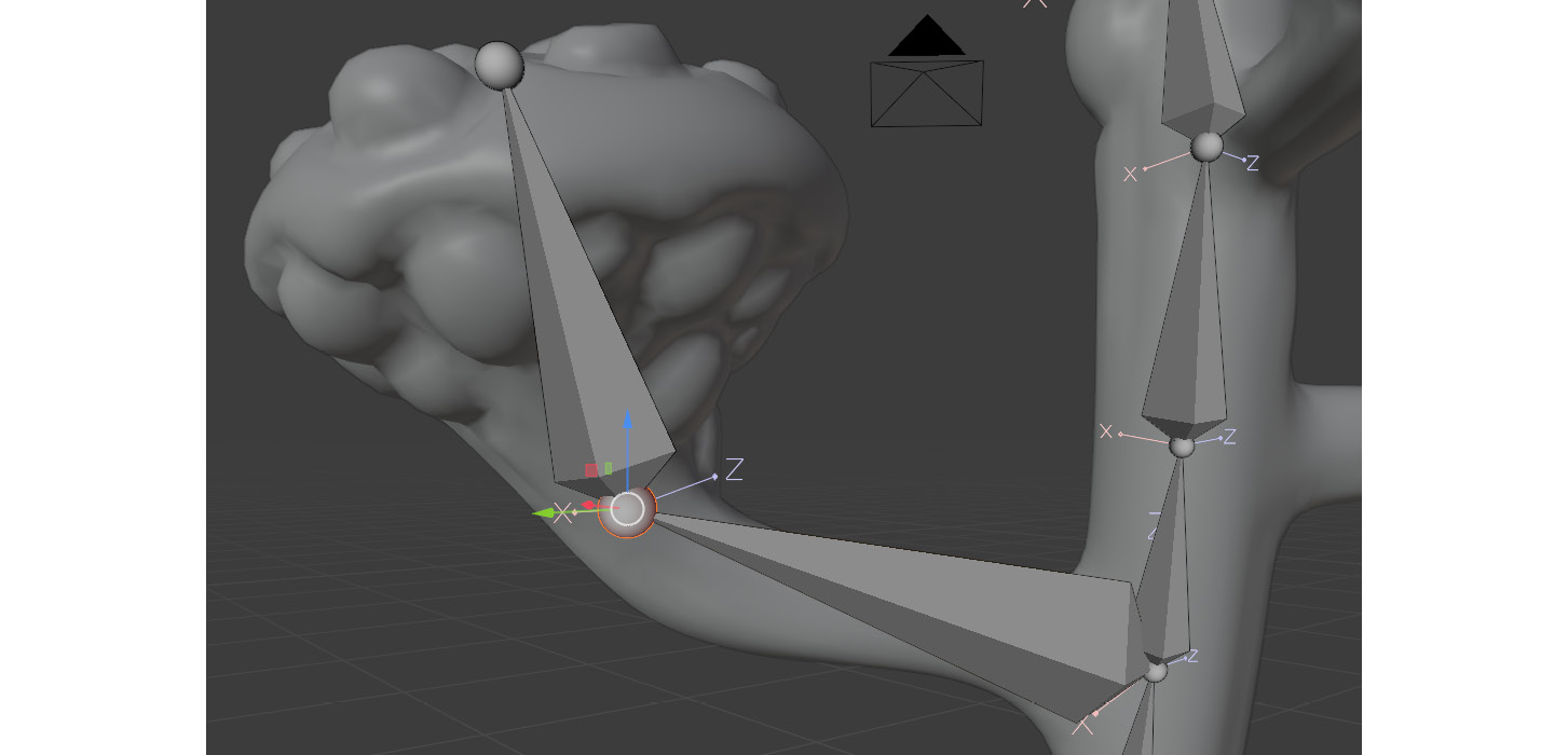
Figure 11.33 – Subdivide bone position
- Select the base joint again and repeat the process following the branch arc, as shown in Figure 11.34:
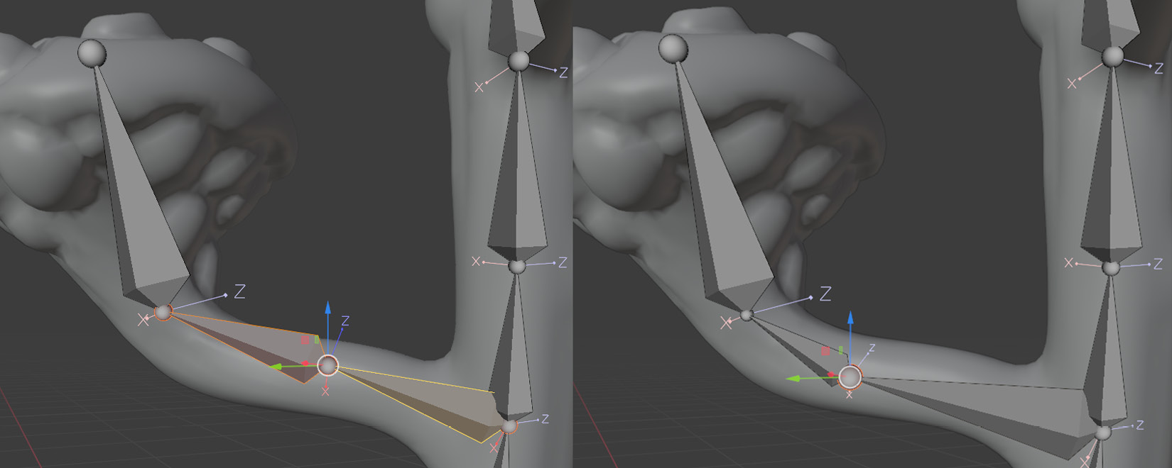
Figure 11.34 – Subdividing bones again and editing position
- Repeat this one final time so that you have a separate joint at the base of the branch too, as shown in Figure 11.35:
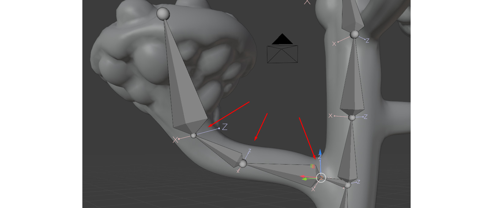
Figure 11.35 – Subdivide bone edit result
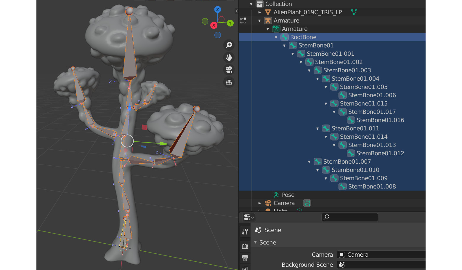
Figure 11.36 – Final result after creating all the bones in the skeleton
- Finally, it's best to rename your bones to something that will make sense. It's a good habit to get into since if you do more complex rigging and skinning, good bone names can make the job much easier, as shown in Figure 11.37:
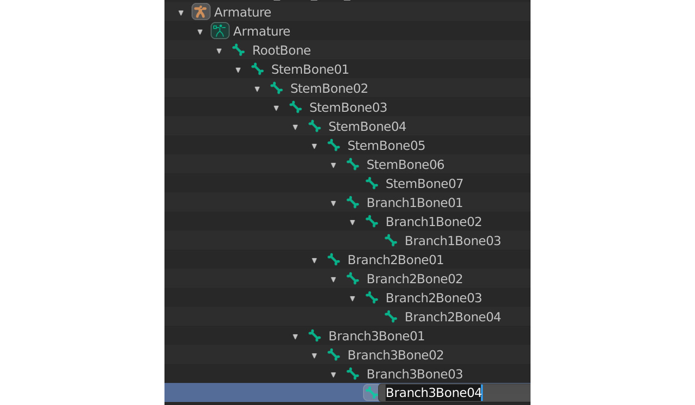
Figure 11.37 – Editing bones by renaming them
- Save this Alien Plant Blender file with a descriptive name in a convenient location to use later in this book.
We have now built a skeleton for our Alien Plant and we are ready to move on to learning about skinning in the next chapter.
Summary
In this chapter, you've learned how to prepare 3D models before you create skeletons for them with some industry best practices. You've created a skeleton for your Alien Plant and got a deeper insight into how it works. You are well on your way to creating custom animatable characters.
In the next chapter, we will learn all about skinning and how it works.