
Chapter 7: Setting Up Materials in UE 5
In the previous chapter, you learned the basics of Unreal Engine 5's (UE5's) UI, basic navigation, and shortcuts.
In this chapter, you will learn the process of importing models and textures and creating materials for 3D assets.
The materials that you will create will use the textures that you exported in Chapter 5, Texturing Your Models inside Quixel Mixer.
In this chapter, we're going to cover the following main topics:
- Importing models into UE5
- Learning the basic UI of the Material, Texture, and Static Mesh Editors
- Importing textures into UE5
- Creating materials in UE5
- Previewing your models with basic lighting
By the end of this chapter, you will have completed both the Robot Drone and Alien Plant's UE materials setup, making them ready to be animated and placed into your virtual 3D movie set.
In the next section, we will take you through the model import process in UE5.
Technical requirements
The following are the technical skills and software you will need to complete this chapter:
- A computer that can run basic 3D animation software.
- You need to have installed UE 5.0.1. You can download it from https://www.unrealengine.com/en-US/download.
- Have a basic understanding of how to navigate in UE5. If you skipped ahead, this was covered in Chapter 6, Exploring Unreal Engine 5.
The files related to this chapter are placed at https://github.com/PacktPublishing/Unreal-Engine-5-Character-Creation-Animation-and-Cinematics/tree/main/Chapter07
Importing your 3D assets
Let's start by importing the Robot Drone and Alien Plant models into UE5.
If you prefer to use the provided models instead of your own models for this tutorial, download the RobotDrone.fbx and AlienPlant.fbx model files from the online repository here:
https://github.com/PacktPublishing/Unreal-Engine-5-Character-Creation-Animation-and-Cinematics/tree/main/Chapter07
These are Static Mesh versions of the models. We will only use these models for the material creation process:
- Create a new folder in the Content Browser panel by right-clicking on the sources view area and in the menu that pops up, selecting New folder. Name this folder RobotDrone and then open this newly created folder.
- Create another new folder inside the RobotDrone folder and name it Model. Open the Model folder.
- Drag and drop the RobotDrone.fbx model from the file's location on your computer into the asset view area of the Content Browser panel. The asset view area is shown in Figure 7.1:
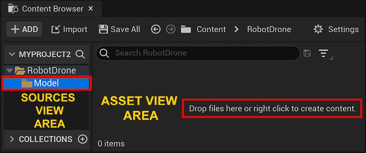
Figure 7.1 – Dragging and dropping your model file onto the asset view area of Content Browser
- Once you have dropped your model file in the asset view area of the Content Browser panel, the FBX Import Options window will open up. Match your settings to the settings that are shown in Figure 7.2:

Figure 7.2 – The import settings for your Static Meshes
- Once you have matched the settings shown in Figure 7.2, click on Import All to complete the import of the model, as highlighted in Figure 7.2. Your RobotDrone model will now be imported into the Model folder.
- Repeat the same import process for the Alien Plant. Create a new folder for the Alien Plant in the sources view area named AlienPlant.
- Create another new folder inside the AlienPlant folder, name it Model, and open it.
- Drag and drop the AlienPlant.fbx model into the asset view area. Use the settings shown in Figure 7.2. Your AlienPlant model will now be imported into the Model folder.
Now, both models will be visible in their respective Model folders in the sources view area. You will also see the icons of the untextured models that are displayed in the asset view area. When an asset is untextured, it will display a checker pattern on its surface.
You've successfully completed the model importing stage of this chapter. In the next section, we will import the textures that you've exported from Quixel Mixer.
Tip
A good practice when working in UE is to save your work regularly. To save all levels and assets to your hard disk, just click on File | Save All. Alternatively, you can use the Ctrl + Shift + S shortcut. The Ctrl + S shortcut will save the current level only.
Importing textures
Importing textures into UE 5 is a really simple process. Let's start with the Robot Drone's textures first:
- Create two new folders inside the RobotDrone folder in the sources view area of the Content Browser panel. Name the first folder Textures and the second folder Materials. Open the Textures folder.
- Select all the Robot Drone's exported textures in their location on your hard drive. These are the textures that you exported from Quixel Mixer at the end of Chapter 5, Texturing Your Models inside Quixel Mixer. These textures are the following: RobotDrone_Albedo.png, RobotDrone_AO.png, RobotDrone_Metalness.png, RobotDrone_Roughness.png, and RobotDrone_Normal.png.
Note
If you prefer to use the provided textures instead of using your own exported textures, you can download all of these textures (for the Robot Drone and Alien Plant) from the online repository here: https://github.com/PacktPublishing/Unreal-Engine-5-Character-Creation-Animation-and-Cinematics/tree/main/Chapter07.
- Drag and drop all five of the Robot Drone's exported textures from your hard drive's location into the asset view area of the Content Browser panel. This will add the textures to the Textures folder. You will notice that each texture has an asterisk symbol in the bottom-left corner of its icon. This asterisk indicates that the textures have not been saved yet, as shown in Figure 7.3:

Figure 7.3 – The Robot Drone's textures are now added to Content Browser
- Repeat the same process for the Alien Plant's exported textures. Create two new folders inside the AlienPlant folder. Name the first folder Textures and the second folder Materials.
- Select the AlienPlant's Textures folder and then drag and drop the Alien Plant's exported textures (AlienPlant_Albedo.png, AlienPlant _AO.png, AlienPlant_Roughness.png, and AlienPlant_Normal.png) into the asset view area of the Content Browser panel.
You have just learned how to create new folders and import textures into Content Browser.
In the next section, we will see how to change the settings for each texture by using the Texture Editor in UE5.
The Texture Editor
The Texture Editor is used to change the settings of textures in UE5. In Figure 7.4, you can see a screenshot of the Texture Editor (without a texture loaded).
Instead of explaining every part of this Editor, we will focus on the parts that you need for this tutorial. This is to prepare you for setting up your own textures. There are more advanced options in this editor, but that is beyond the scope of this book:

Figure 7.4 – The three areas of the Texture Editor's UI that we will focus on
The three areas of the Texture Editor's UI that we will focus on are listed as follows and correspond to the numbers of the UI regions in Figure 7.4:
- Toolbar: Here, you will find the Save icon.
- Viewport: This is your view of the texture that you are editing.
- Details panel: You can change the settings and view details of your texture here.
Let's start by editing the RobotDrone_Albedo texture first:
- Double-click on the RobotDrone_Albedo texture in the asset view area. This will open up the Texture Editor window. The selected texture is automatically preloaded into the Texture Editor.
- With the RobotDrone_Albedo texture loaded into the Texture Editor window, set the settings in the Editor's Details panel to the following:
- Under the LEVEL OF DETAIL drop-down menu, set Mip Gen Settings to NoMipMaps.
- Check that under the COMPRESSION drop-down menu, Compression Settings is set to Default (DXT1/5, BC1/3 on DX11).
- Under the Texture drop-down menu, check the sRGB checkbox. Save the texture and close this window.
You have prepared your first texture successfully. I have highlighted all of the settings from this step, including the Save button, in Figure 7.5:

Figure 7.5 – Setting up an Albedo texture in the Texture Editor
- Double-click on the RobotDrone_AO texture to load it into the Texture Editor. Apply the same settings that you have just used for the Albedo texture in the previous step, except this time, uncheck the sRGB checkbox in the Texture drop-down menu, to disable sRGB (only Albedo textures should have the sRGB option enabled).
- Repeat Step 3 for both the RobotDrone_Metalness texture and the RobotDrone_Roughness texture.
- Double-click on the RobotDrone_Normal texture to load it into the Texture Editor and do the following:
- Under the LEVEL OF DETAIL drop-down menu, set Mip Gen Settings to NoMipMaps.
- Check that under the COMPRESSION drop-down menu, Compression Settings is set to Normalmap (DXT5, BC5 on DX11).
- Under the Texture drop-down menu, make sure the sRGB checkbox is unchecked.
- Still under the Texture drop-down menu, click on the small downward-pointing arrow before the heading named Advanced to open the drop-down menu, then check on the checkbox for Flip Green Channel, as shown in Figure 7.6:

Figure 7.6 – Check the Flip Green Channel checkbox for Normal Maps that are exported from Quixel Mixer
Note
Quixel Mixer uses a Normal Map system with its green channel (Y) set in the positive direction: (X: +, Y: +, Z: +).
UE uses a Normal Map system with its green channel (Y) set to the negative direction: (X: +, Y: -, Z: +).
The X, Y, Z coordinates correlate to the R, G, B color channels. The reason we're flipping the green color channel of the Normal Map textures inside UE is to correct the way that light bounces off a mesh's surface. If the green color channel is flipped, it will invert the direction of bumps to look like they are indentations, and vice versa.
- You will now repeat the texture preparation process for the Alien Plant. For the AlienPlant_Albedo texture, use Step 2. For the AlienPlant_AO texture and the AlienPlant_Roughness texture, use Step 3. For the AlienPlant_Normal texture, use Step 5.
Note
The Alien Plant does not have a Metalness texture map.
You've just learned how to set up all the textures for the Robot Drone and the Alien Plant. In the next section, I will take you through the process of setting up materials.
Creating materials
Let's now use the textures that you prepared in the previous section to create materials for your Robot Drone and Alien Plant.
Note
For those of you who wish to skip the materials setup part of this tutorial, you can download the completed materials from the online repository at https://github.com/PacktPublishing/Unreal-Engine-5-Character-Creation-Animation-and-Cinematics/tree/main/Chapter07/AlienPlant/Materials
and from here: https://github.com/PacktPublishing/Unreal-Engine-5-Character-Creation-Animation-and-Cinematics/tree/main/Chapter07/RobotDrone/Materials.
Let's create your first material in Content Browser by following these simple steps:
- Open RobotDrone's Materials folder in the sources view area of the Content Browser panel.
- Right-click in the asset view area of the Content Browser panel. This will open a menu. In the CREATE BASIC ASSET section of this menu, select Material, as shown in Figure 7.7:
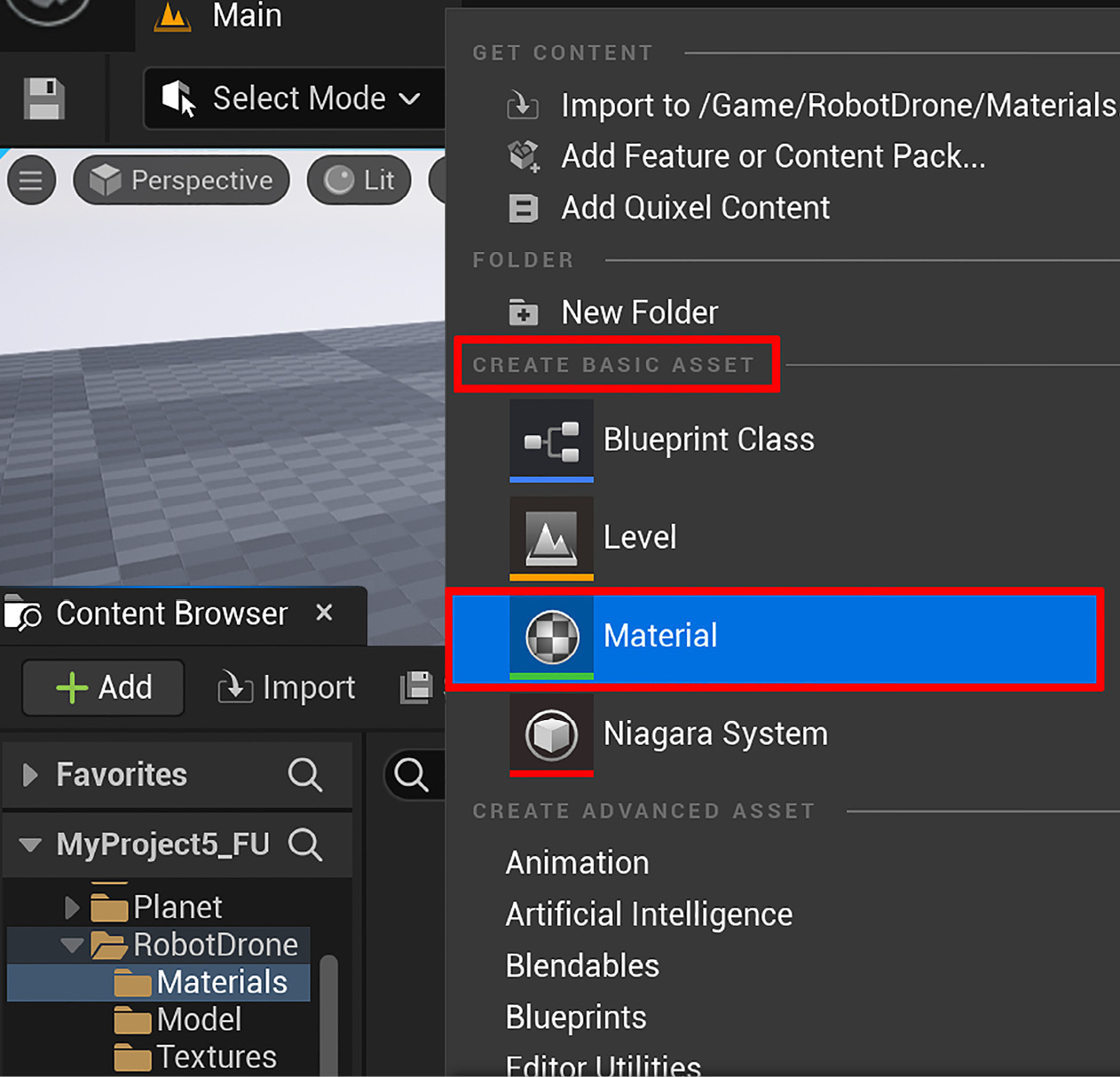
Figure 7.7 – Creating a new material
- This will create a new material in the asset browser that doesn't have any textures connected to it yet. Name this material M_RobotDrone. You can see your new material in Figure 7.8:
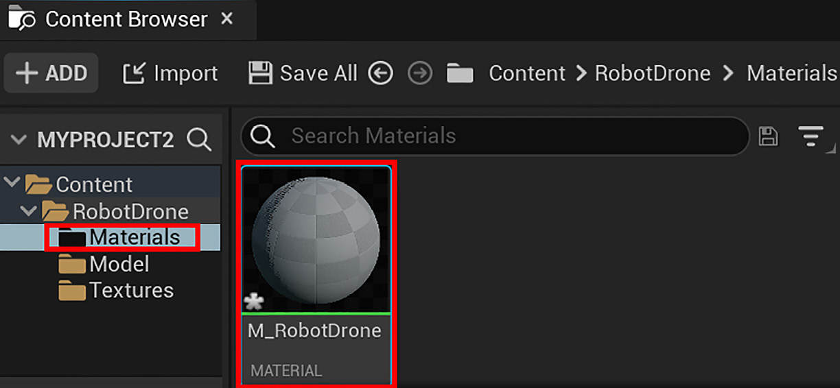
Figure 7.8 – Your new material in the asset view area of Content Browser
- Repeat this process (Step 1 and Step 2) for the Alien Plant. Create a new material in AlienPlant's Materials folder and name this material M_AlienPlant.
- Double-click on the newly created M_RobotDrone material. This will open the Material Editor window with the currently selected material preloaded in the Material Editor. In Figure 7.9, you can see a screenshot of the Material Editor. I have numbered and highlighted the parts we will focus on.
You have just learned how to create a new material in UE5. In the next section, we will explore the Material Editor window.
The Material Editor
The Material Editor is used to connect textures to a Base Material node. The Base Material node is a visual representation of your material. For each texture that you connect to this node, you are describing a specific property of your material.
For example, if you connect your Roughness map to the node, you are describing how rough or smooth areas of your material will be. You can have multiple textures that can describe multiple aspects of the same material. For example, a model of a cube can have areas on its material that are smooth described by the Roughness map and also metallic described by the Metalness map.
Let's now explore the UI regions of the Material Editor that opened up automatically when you double-clicked on a material in Content Browser's asset view area.
In Figure 7.9, you will see a screenshot of the Material Editor window. I have added numbers and highlights to indicate the different UI regions for explanation purposes:
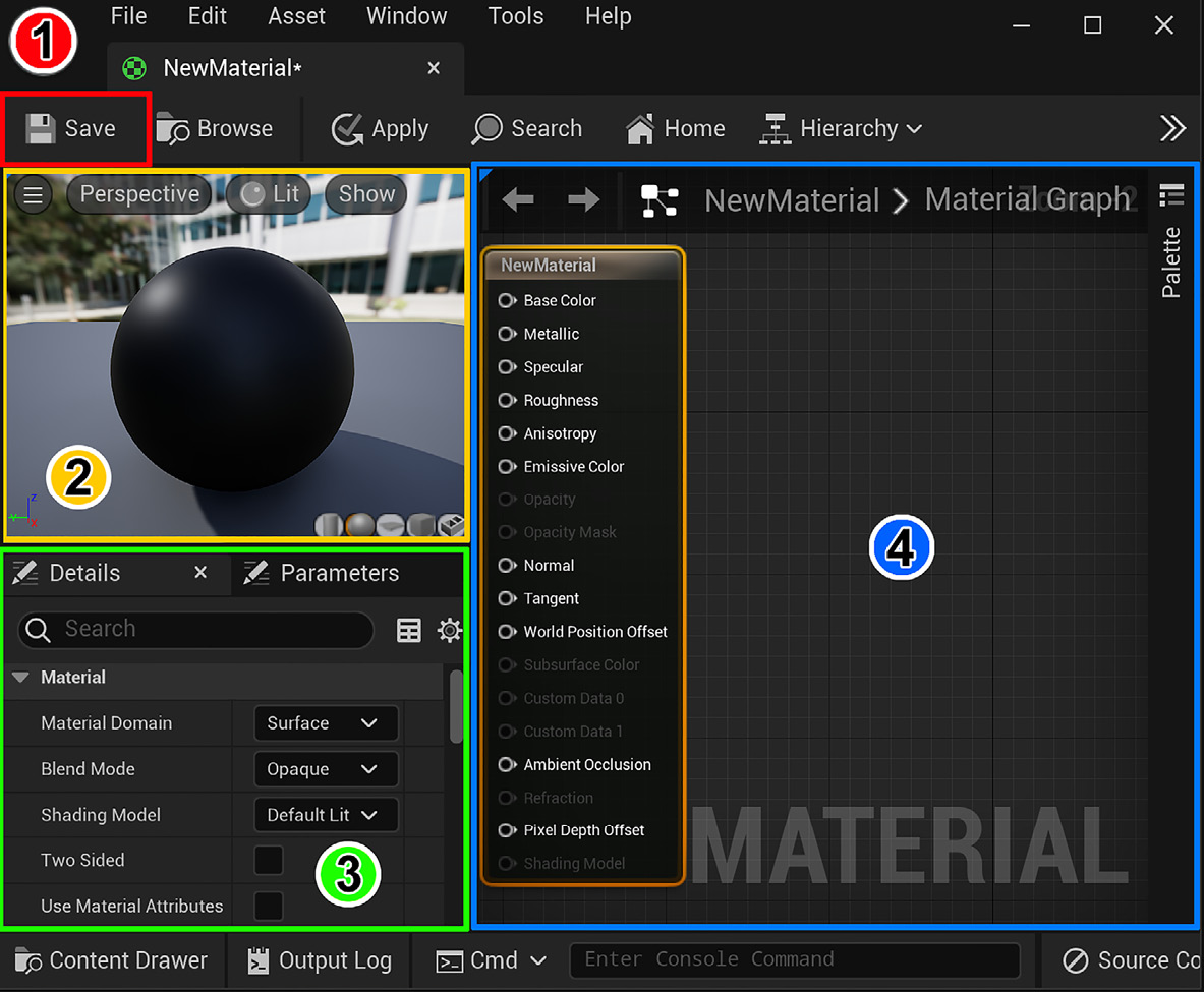
Figure 7.9 – The Material Editor's regions
The following are the UI regions that are shown in Figure 7.9:
- Toolbar: Here, you will find the Save icon.
- Viewport panel: View of your material.
- Details panel: Displays details and changeable settings for your material.
- Graph panel: Where you connect textures to the Base Material node.
Let's start by setting up the material for the Robot Drone:
- Reduce the size of the Material Editor window by clicking on the Restore Down icon (the icon with two squares, on the top-right side of the window). Drag and drop all five of the Robot Drone's textures from Content Browser into the Material Editor's Graph panel.
Tip
Inside the Material Editor's Graph panel, use the mouse wheel to zoom in or out. Click and drag the right mouse button to pan.
- Move the textures to the same positions that are shown in Figure 7.10.
- Note that the Base Material node is already inside the Graph panel when you open it, so just move the five textures to the left of it. The Details panel will display the texture name when you click on a texture.

Figure 7.10 – The Graph panel with your Robot Drone's textures and the Base Material node
Next, we will start connecting the textures to the Base Material node.
- Let's start with the Albedo texture. Left-click on the RGB output, as shown in Figure 7.11, Part A. Then, drag the connection and connect the line to the Base Color input in the Base Material node and then release the mouse button. As seen in Figure 7.11, Part B, (Base Color is the same as Albedo).
You have just learned how to connect a texture to a Base Material node.

Figure 7.11 – Connecting a texture to the Material node: (A) Dragging the connection from the RGB output (B) Connecting it to the Base Color input
- Connect the Metalness output to the Metallic input, the Roughness output to the Roughness input, the Normal output to the Normal input, and the AO output to the Ambient Occlusion input of the Base Material node, as shown in Figure 7.12:

Figure 7.12 – Connecting the rest of the textures to the Base Material node
- For the last step, just click on the Save icon. This will save the changes you've made to the material. Now, close the Material Editor window.
- Repeat the same process (Step 1 to Step 5) for the M_AlienPlant material but use the four textures of the Alien Plant to create this material, then save it.
You've successfully completed the materials for the Robot Drone and the Alien Plant.
In this section, you've just learned how to create new materials in UE5. You have also learned how to connect the textures that you've exported from Quixel Mixer to create UE-compatible materials.
In the next section, we will see how we can now apply these materials to the models.
The Static Mesh Editor
The Static Mesh Editor is used to change the settings of Static Meshes in UE5. We can also use it to assign a particular material to your Static Mesh.
You've completed all your texture imports for both the Robot Drone and Alien Plant and edited their individual texture settings. After this, you created new materials for these models. Finally, you are now ready to apply these materials to your models.
We will apply the materials by using the Static Mesh Editor. But first, we need to go over the basic UI regions we will use for this tutorial. In Figure 7.13, you can see a screenshot of the Static Mesh Editor window. I have added numbers and highlights to indicate the different UI regions for explanation purposes:
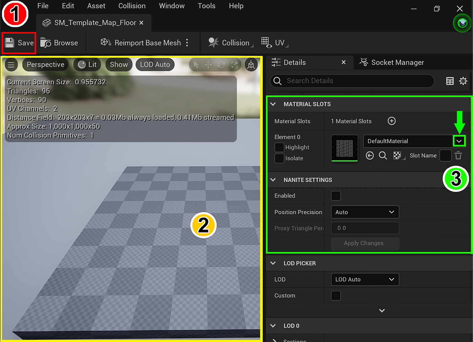
Figure 7.13 – The Static Mesh Editor's UI and the highlighted parts that we will focus on
The following numbers correspond to the UI regions that are shown in Figure 7.13:
- Toolbar: Here, you will find the Save icon.
- Viewport panel: This is your view of the model that you are editing.
- Details panel: You can change settings, view details, and assign materials to your models here. The Material Slot drop-down selection menu is indicated by the green arrow.
Let's get started by assigning the Robot Drone's material first, then we will move on to the Alien Plant's material:
- Open the RobotDrone folder.
- Inside the asset view area, double-click on the RobotDrone model (Static Mesh). This will open the Static Mesh Editor, as shown in Figure 7.13. The RobotDrone Static Mesh will be preloaded and displayed in the Viewport panel.
Note
The model will still have a checker pattern applied at this point.
- In the Details panel, click on the Material Slot drop-down selection menu, which is indicated by the green arrow in Figure 7.13.
- In this drop-down menu, you will see the two materials that you created earlier. Select the M_RobotDrone material. This will replace the checker pattern on the Robot Drone's surface with the material you created for it.
- Click on the Save icon to save the changes you've made to the Static Mesh.
- Repeat the same process (Steps 1–5) for the Alien Plant model (Static Mesh) by applying the M_AlienPlant material to it.
In this section, you have learned how to use the Static Mesh Editor to assign a material to a Static Mesh. You will essentially use the same process for the Skeletal Mesh versions of the Robot Drone and Alien Plant later on by using the Skeletal Mesh Editor. In later chapters, we will take you through all the steps to assign a material to a Skeletal Mesh.
Now that you have materials assigned to both the Robot Drone and Alien Plant, it is time to see how they look in the Viewport.
In the next section, I will show you how to adjust the lighting in the scene so that you can see the materials better, since the default lighting has very dark shadows.
Previewing your models with lighting
The purpose of this section is to show you some very basic lighting methods to use for previewing your 3D assets. In Chapter 10, Adding Lighting and Atmospheric Visual Effects in UE5, you will have an in-depth exploration of the subject of lighting.
To get started, let's add RobotDrone and AlienPlant Static Mesh models to the scene (World) to see how they look with the materials you've made. Then, we will adjust the lighting to achieve a more pleasing look:
Note
This part of the process will not be used in your final 3D movie set, since we are using this step to preview what the materials look like on your models.
- Left-click and drag the RobotDrone model (Static Mesh) from the asset view area of Content Browser into the Viewport. Let go of the left mouse button when you are happy with the position of the model in the World.
- With the Robot Drone still selected, look inside the Details panel. Under the Transform heading, change the Z-axis (blue tab) location to 40, as shown in Figure 7.14. This will move the Robot Drone model so that it floats above the ground, instead of intersecting with it (sci-fi Robot Drones are supposed to fly above the ground):

Figure 7.14 – Adjusting the Z-axis location of the Robot Drone
- Now, it is time to place the Alien Plant. Left-click and drag the AlienPlant model (Static Mesh) from the asset view area of Content Browser into the Viewport. Let go of the left mouse button when you are happy with the position of the model in the World. The Alien Plant model does not need any adjustment, because its base is already resting on the ground level.
- Left-click inside the Viewport in an empty space, then press G on your keyboard. This shortcut will toggle the display of the icons and grid in your Viewport so you can see the models better.
- Now that both models are in the Viewport, we will adjust the lighting. In the World Outliner, click on SkyLight. Inside the Details panel, under the Light (heading), set Intensity Scale to 6, as shown in Figure 7.15:

Figure 7.15 – Adjusting SkyLight's Intensity Scale
- In the World Outliner, click on Light Source. Inside the Details panel, under the Light (heading), set Intensity to 10.0 lux, as shown in Figure 7.16:

Figure 7.16 – Adjusting Light Source's Intensity
- Let's interactively adjust the angle of the sunlight in the Viewport. Left-click inside the Viewport in an empty space, then use the Ctrl + L shortcut while moving your mouse, to interactively adjust the angle of the sunlight.
- When you are satisfied with the angle of the sunlight, just release the shortcut keys. In Figure 7.17, I have adjusted the sunlight that is used to light the Alien Plant and Robot Drone, to look more pleasing:

Figure 7.17 – Testing the models with a variety of lighting angles
Testing your models with different types and angles of lighting helps to give you a better idea of what your models will look like once they are placed inside the 3D movie set that we will build later in Chapter 9, Building a Virtual 3D Movie Set in UE5.
In this section, you've just learned how to place your models in the World.
You've also learned how to adjust the properties of the lights in UE5, plus how to interactively adjust the angle of the sunlight.
Summary
You have successfully completed the practical tutorials in this chapter to import your assets, create materials, connect textures to materials, and apply these materials to a 3D asset.
Finally, you've learned how to place your models in the World and how to do some basic adjustments to the lighting for previewing purposes.
In the next chapter, we will explore MetaHuman Creator, which is used to create photo-realistic human characters for use in UE 5. We will go through the step-by-step process to create a sci-fi-style female character.
See you in the next chapter!