
Chapter 3 : Let's Sculpt an Alien Plant!
In Chapter 2, Modeling a Robot Drone Character, you learned how to utilize Blender's excellent modeling tools to create a Robot Drone character.
Modeling tools work great for mechanically shaped models (such as our Robot Drone), but when you want to create a model that has an organic form, 3D sculpting is the best method. That's because it is much more intuitive to use 3D sculpting tools to shape organic surfaces.
This practical tutorial will teach you how to create an organic model for your 3D movie set. So, let's learn how to do this by sculpting an Alien Plant model! These plants would look amazing in your Alien Planet Surface 3D movie set.
In this chapter, you will learn how to sculpt a mesh in Blender, as if it were a piece of virtual clay.
You'll be guided through the complete 3D sculpting process, which will start with setting up the reference image and the block-out stage of your model.
Next, you will learn how to combine all these parts into a single high-resolution mesh that you will sculpt on. Once your sculpted model is complete, you will learn how to convert it into a lower-resolution mesh for use in Unreal Engine 5 (UE5).
In this chapter, we're going to cover the following main topics:
- Blocking out your model
- Fixing problem areas
- Adding secondary and tertiary forms
- Generating the low-resolution mesh
The techniques you will learn in this chapter are essential as a base for 3D sculpting in Blender. After completing this practical tutorial, you will have a solid understanding of the 3D sculpting workflow and its tools. You will be able to create 3D sculptures for use in UE.
Now that you know what we are going to cover in this practical tutorial, let's start by loading the tutorial file and creating the block-out shape of the model.
Technical requirements
You will need the following hardware and software to complete this chapter:
- A computer that can run basic 3D animation software
- Blender, which can be installed from https://www.blender.org/download/
- Instant meshes, which can be downloaded and installed from https://github.com/wjakob/instant-meshes
Scroll down to the bottom and you will find a section called Pre-compiled binaries. Download the .zip file according to the operating system that you are using.
You can download the completed Alien Plant model, called AlienPlant_LP.blend, from this book's GitHub repository: .
Loading the file containing the reference image
First, let's take a quick look at the reference image that I've provided. It is a sketch of the Alien Plant that you will create for your Alien-Planet 3D movie set:
- Download the Alien_Plant_REF.blend file from this book's GitHub repository: https://github.com/PacktPublishing/Unreal-Engine-5-Character-Creation-Animation-and-Cinematics/tree/main/Chapter03.
- Upon opening this Blender file, you will see the reference image of the Alien Plant inside the 3D Viewport. You will also find the AlienPlant_REF item, listed in the Outliner panel. There is also a Cube mesh that has been prepared for this practical tutorial. The following figure shows what the reference image of the Alien Plant looks like:

Figure 3.1 – The reference image of the Alien Plant
Handy Tip
There is an easy way to identify the icons on the toolbar. Just hover your cursor over the right-hand side of the toolbar's edge until the two-directional arrow icon appears. Then, click and drag the toolbar to the right-hand side to expand it. Once the icons have rearranged themselves, drag the toolbar to the right once more to reveal the name of each icon on the toolbar.
In the next section, you will learn how to block out a model.
Blocking out your model
Blocking out means creating a mesh of the "rough approximate shape" of the model you want to sculpt. It can be created from low-resolution (low geometric density) meshes to create a base for the 3D sculpture.
In the next section, you will use the Cube mesh that has been prepared for you and extrude it into the shape of the Alien Plant.
Extruding and duplicating mesh parts
Now that you have loaded the Blender file containing the Cube mesh and reference image, we need to convert this Cube mesh into the rough approximated shape of the Alien Plant.
The easiest way to do this is by using the Extrude function on the Cube mesh's faces. We will do this in small incremental steps so that we can modify the position, rotation, and scale of the newly created geometry each time that we perform an extrusion. Let's get started:
- Select the very top face of your Cube mesh.
- Press E to extrude this face upward. Only extrude it by a small amount so that it matches the outlines of the Alien Plant's trunk; this is shown behind the Cube mesh in Figure 3.2, part A.
- Adjust the rotation and scale of the newly extruded faces. Continue these extrusions and adjustments to the top of the plant, as shown in Figure 3.2, part A.
- Refine the shape of the mesh by adding more Edge Loops by using the Ctrl + R shortcut. Then move, rotate, and scale the Edge Loops so that they match the shape of the plant's trunk and top, as shown in Figure 3.2, part B:
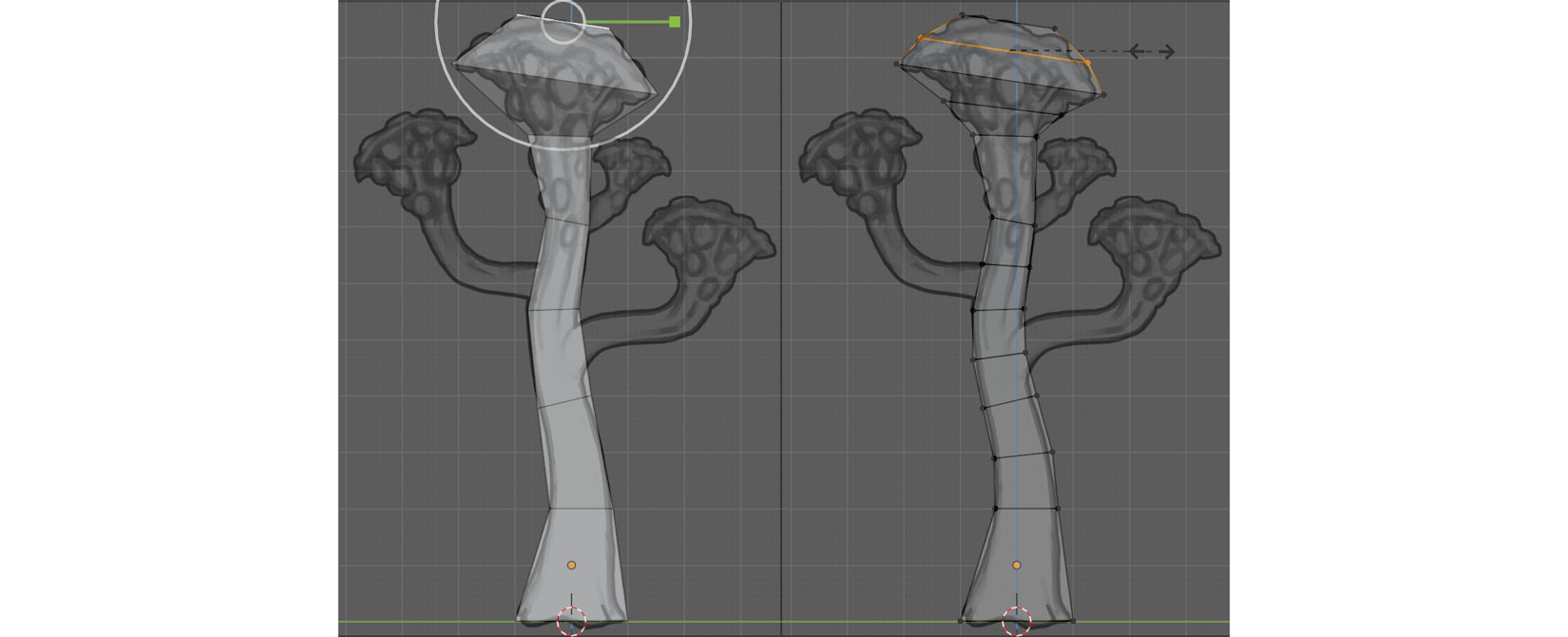
Figure 3.2 – (A) Extruding the Cube mesh's faces upwards to create the basic trunk shape;(B) Refining the form by adding more Edge Loops and adjusting them
- Once your model looks approximately similar to the model in Figure 3.2, part B, it is time to move on to the next stage.
- Press Alt + Z to toggle on X-Ray Viewport Shading Mode (toggle it on or off as needed). X-Ray Viewport Shading Mode allows you to select the mesh's components right through the mesh (on the opposite side of your current view).
- Select the faces of the Alien Plant's head (the top) plus approximately six of the trunk's segments below the head.
- Duplicate these faces by pressing Shift + D. Then move, rotate, scale, and edit the vertices of the duplicated mesh to fit it to the shape of the big branch that is shown on the bottom right-hand side of the reference image. This step is shown in Figure 3.3, parts A and B.
- Repeat this process for the remaining two branches by duplicating this branch twice and manipulating it so that it fits the other two branches. The result of the model with the duplicated branches should look like the model shown in Figure 3.3, part C:
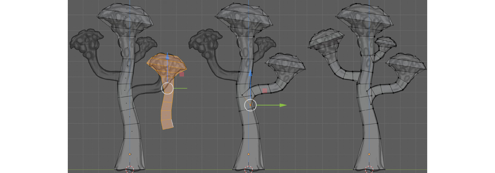
Figure 3.3 – (A) Duplicating the top part of the mesh; (B) and (C) Modifying the shape of the duplicated branches so that they fit the shape of the other branches
Now that we have the main shapes of our Alien Plant blocked out, we can see that it looks a bit too mechanical from the top and front Orthographic views since all the branches and the direction of the trunk's curvature are only in the Y-axis direction. See the BEFORE view in Figure 3.4.
- Let's add some organic variation to the shape of the trunk. Select some of the mesh components. Press O to enable Proportional Editing, then rotate and move these selected mesh components into a slightly bent shape so that the trunk is bent in both the X-axis and Y-axis directions. The result should look like the AFTER view in Figure 3.4.
Note
To select all the linked components on a mesh, select one component on it and press Ctrl + L to use the Select Link function.
Now, you should have a mesh that resembles a more organic-shaped Alien Plant, as shown in the AFTER view in the following diagram:
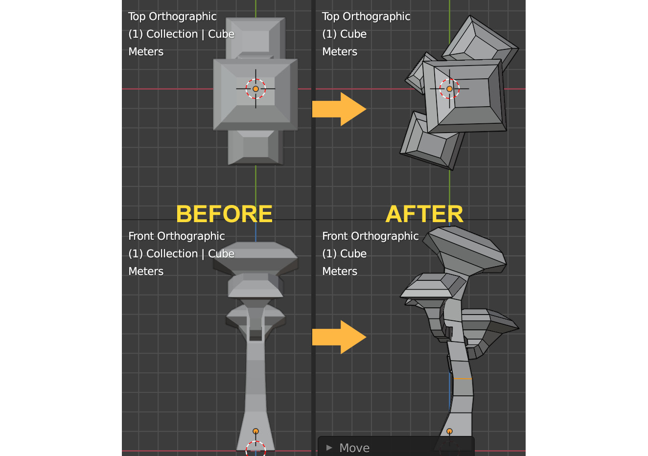
Figure 3.4 – Adjusting the shape of the trunk and rotating the branches
- There is one last thing we need to do before our block-out mesh is completed. We need to add two Edge Loops very close to the bottom of the base of the trunk, as shown in the following screenshot:
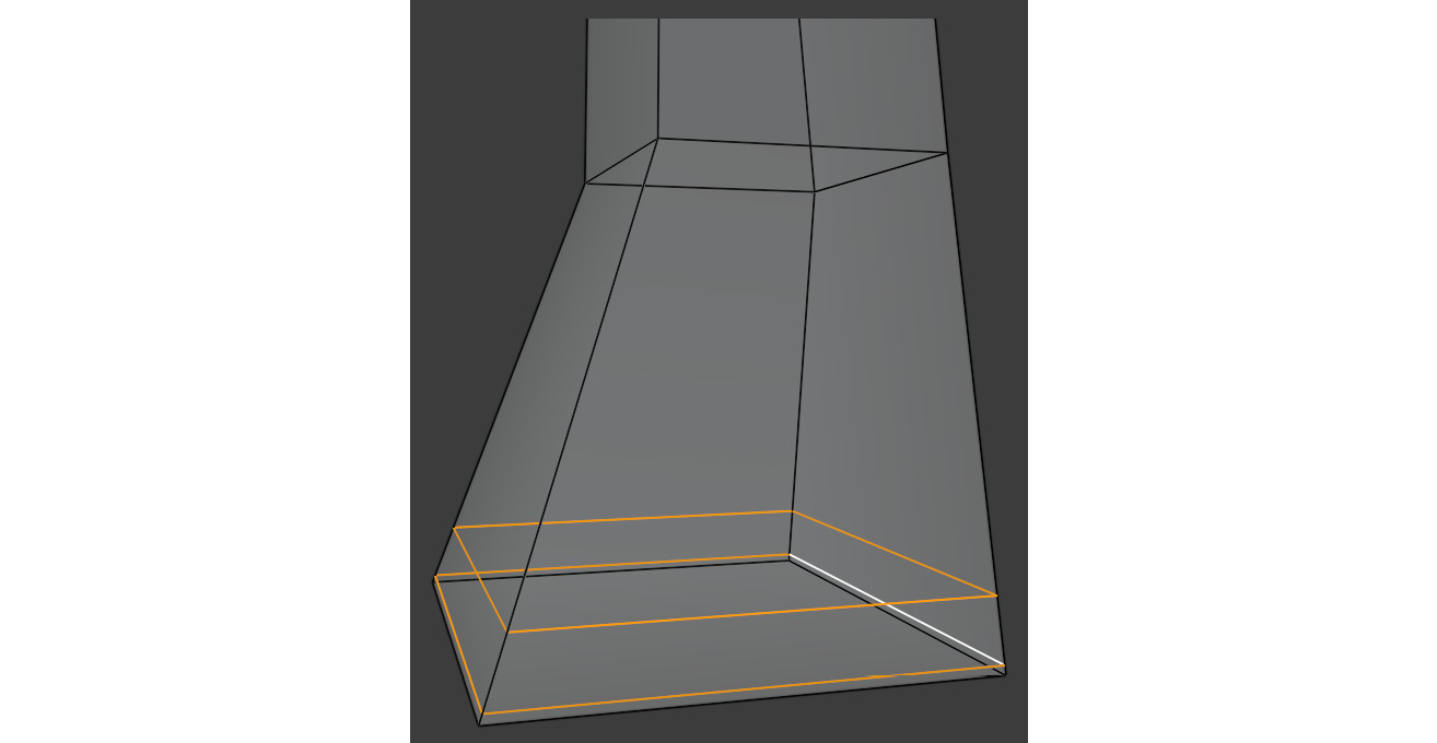
Figure 3.5 – Adding two Edge Loops to the base of the trunk
The block-out stage of the model is now complete and we're ready for the next stage! In this section, you learned how to create a block-out of a model and how to follow the shape of the reference image. You can use the same technique for any of your future 3D work.
In the next section, you will learn how to add higher geometric density to this mesh.
Important
Before you use functions in Blender that add new geometry to your mesh (such as Remesh, Dyntopo, Subdivision Surface Modifier, or Multiresolution Modifier), you need to take your computer system's specifications (CPU, video card, and RAM) into account. The denser the geometry of the mesh becomes, the more system resources your computer will need.
Subdividing the mesh
All the shapes of the Alien Plant have now been blocked out.
Since this mesh is still very blocky looking (because of its low-resolution geometry), we need to convert the mesh into a high-resolution mesh so that we can deform it with the 3D sculpting brushes. Follow these steps:
- Select the model in Object Mode and press Ctrl + 5 on your keyboard to turn the mesh into a smooth and rounded shape! By using that shortcut, you've automatically added the Subdivision Surface Modifier to your mesh, which is now visible in the Properties panel under the Modifier Properties tab:

Figure 3.6 – Adding the Subdivision Surface Modifier to the mesh
- Here, you will see that it lists Modifier as Subdivision. Set Levels Viewport to approximately four to five subdivisions.
- Before you can sculpt the mesh, you need to apply the modifier to the mesh by using the Ctrl + A shortcut, while your mouse pointer is hovering over the modifier.
You will notice that the mesh's simple wireframe suddenly displays a lot of new faces. This is exactly what we want for 3D sculpting.
In this section, you learned how to subdivide the block-out mesh by using the Subdivision Surface Modifier and then used the Apply function to apply the modifier to the mesh.
The model is now prepared and has a high resolution (high mesh density).
In the next section, we will use the Remesh function on the model so that all the branches are joined up into one surface. Then, we can continue to the fun part: sculpting some of the big surface shapes – that is, making the primary forms.
Sculpting the primary forms
To start the 3D sculpting process, you need to use the Remesh function in Blender's Sculpting Workspace.
Important Note
The quoted figures for Remesh's Voxel Size should be used as a suggestion. The actual number depends on what your computer system can handle, so adjust these numbers accordingly.
Follow these steps:
- Click on the Remesh button on the Header bar. The Remesh function was explained in Chapter 1, An Introduction to Blender's 3D Modeling and Sculpting Tools.
- In the drop-down menu that opens, set Voxel Size to the approximate size of 0.02 m. The smaller the number, the higher the mesh's density.
- Now, either click on the Remesh button at the bottom of the drop-down menu or use the Ctrl + R shortcut to remesh your mesh.
- Once you've applied the Remesh function to your mesh, you will see that your mesh's surface has been divided into more faces (it has a much higher geometric density than before). You will also notice that the previously separate branch meshes have been combined into a single mesh.
You can repeat this process any time your mesh becomes too blocky (or when it has a stretched topology). The remeshed mesh topology will replace the stretched mesh topology with a new, evenly divided mesh that works great for 3D sculpting.
- Zoom in closer to where the branches join up with the trunk of the Alien Plant. Select the Smooth brush from the toolbar.
- Press Shift + F to open the Brush Strength pop-up menu and set the amount to 0.3. Now, brush over the parts where the branches join the trunk. You will observe that this smooths out the sharp line where they joined up. The smoothed lines will create a great transition between the different surfaces, as shown in the following screenshot:
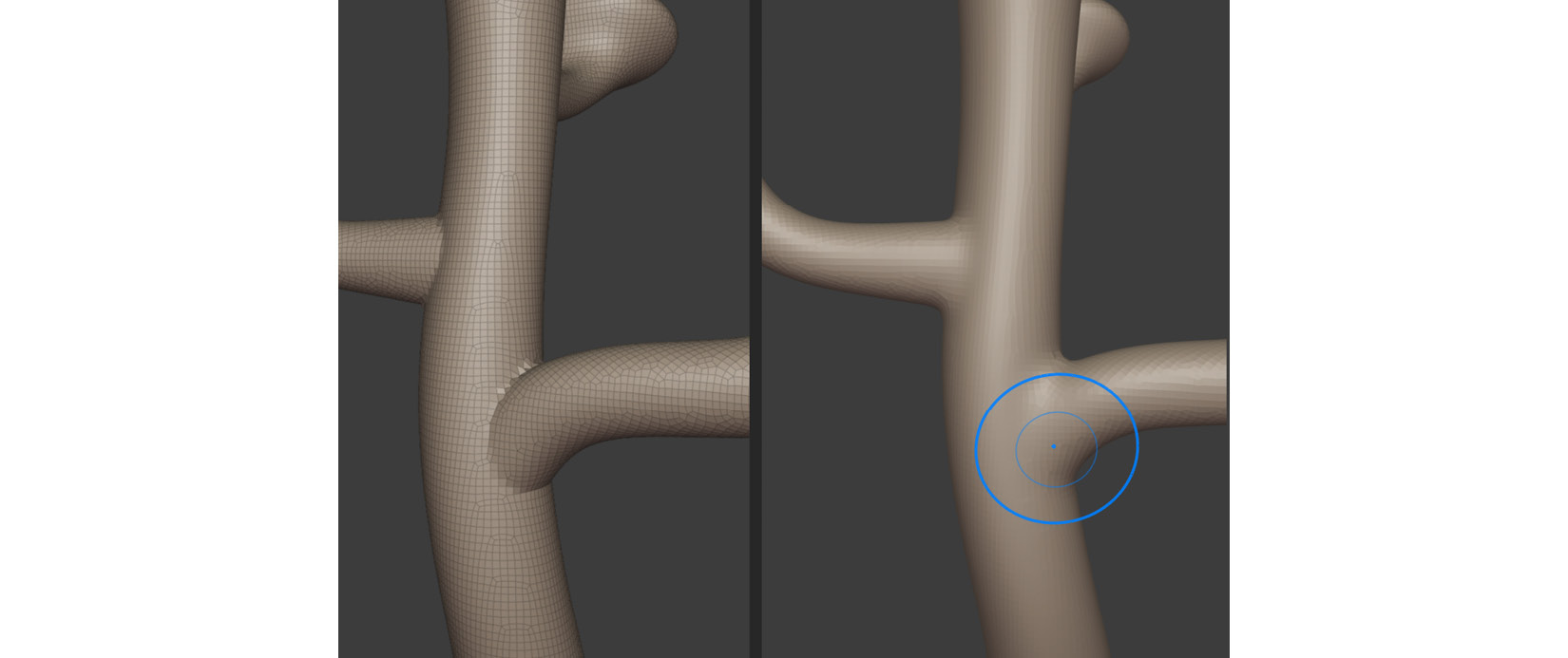
Figure 3.7 – Smoothing the joined parts
- Now, let's move on to the base of the trunk. Zoom in closer and select the Draw brush from the toolbar. We will start our sculpting here. The shape of the trunk is a primary form since it is an important feature that we can notice even when we've zoomed out or are looking at the silhouette.
- Set Brush Strength to 0.4 and start with medium-sized strokes. Brush gently over the base of the trunk to pull out the shapes.
If you want to push the surface inwards (in the negative brush direction), you can use the Ctrl button while sculpting, as shown in the following screenshot:
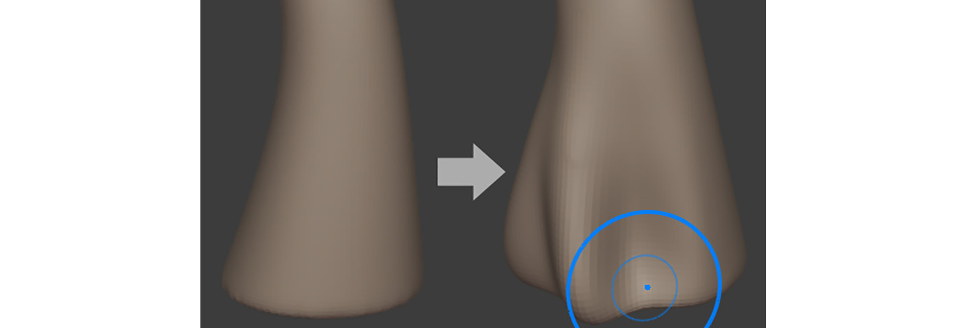
Figure 3.8 – Sculpting the base of the trunk
If you want to smooth the surface while sculpting, you can hold the Shift key while sculpting. This function works with the Draw brush, Draw Sharp brush, and Inflate brush.
You have just completed your first 3D sculpting exercise. You now know how to use the Draw brush, which is one of the most important sculpting tools in Blender.
You've practiced how to use the brush in both positive and negative directions, as well as how to use the Smoothing function. With more practice, your skill at handling the sculpting brushes will greatly improve.
In the next section, you will learn how to fix some common sculpting issues.
Fixing problem areas
From time to time, every 3D sculptor will encounter some common 3D sculpting issues. Let's look at how to fix some of these now.
Flattening an area of the mesh
Since you are sculpting the base of the trunk, parts of the geometry will move below the floor grid level. As seen to the left of the following screenshot, the base of the trunk is dipping below the dotted line.
To correct this, there is a handy tool in the 3D sculpting toolset called the Line Project brush. Let's learn how to use it:
- With the Line Project brush selected, left-click and start to draw a line from the left toward the right-hand side.
- Hold Ctrl while drawing to snap the line at an angle that's parallel to the floor grid.
- Release the left mouse button once you have drawn the line past the base of the trunk. The overhanging part of the mesh will now be flattened out. You may have noticed that the area below the line is shaded darker than the area above the line. The Line Project brush will flatten the area of the mesh that is on the shaded side of the line, as shown in the following screenshot:
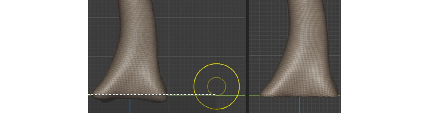
Figure 3.9 – Using the Line Project brush to flatten overhanging geometry
- Slightly smooth out the sharp edges of the base of the trunk.
In this section, you learned how to flatten a part of a mesh with the Line Project brush. Now, let's learn how to fix surface artifacts.
How to fix surface artifacts
Mesh surface artifacts are irregularities on the mesh's surface. These can be caused by various things, but one of the main effects is a surface that has strange pinching or smoothing errors, as shown in the following screenshot.
Important Note
The quoted figures for Dyntopo's Detail Size should be used as a suggestion. The actual number depends on what your computer system can handle, so adjust these numbers accordingly.
The following screenshot shows what surface artifacts can look like. As you can see, they cause unwanted surface details:

Figure 3.10 – An example of mesh surface artifacts.(A) The Wireframe Viewport overlay turned on; (B) A regular view of the surface artifacts
If there are any artifacts on your 3D sculpture model's surface, follow these steps:
- Press Ctrl + D to toggle on the Dyntopo brush. Alternatively, use the Dyntopo button in the Sculpting Workspace Header bar, as shown in the following screenshot.
- Set Brush Strength to 0.
- From the Dyntopo drop-down menu, set Detail Size to 5.00 px:
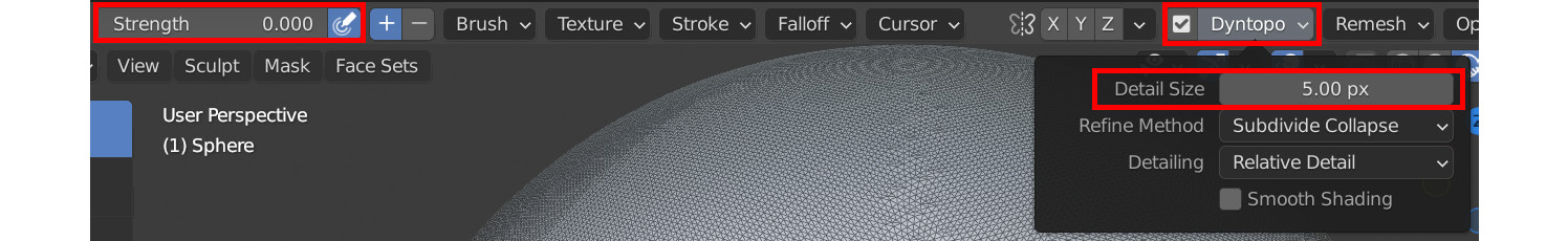
Figure 3.11 – Use these settings to fix surface artifacts with the Dyntopo brush
- Select the Draw brush and gently brush the problem area. This will add geometric detail while keeping the shape of the mesh intact. In the following screenshot, I used the Dyntopo brush with the Draw brush to replace the surface artifacts with new small triangular faces.
- Smooth the problem area out slightly, as shown in the following screenshot. As you can see, the surface artifacts have been fixed:
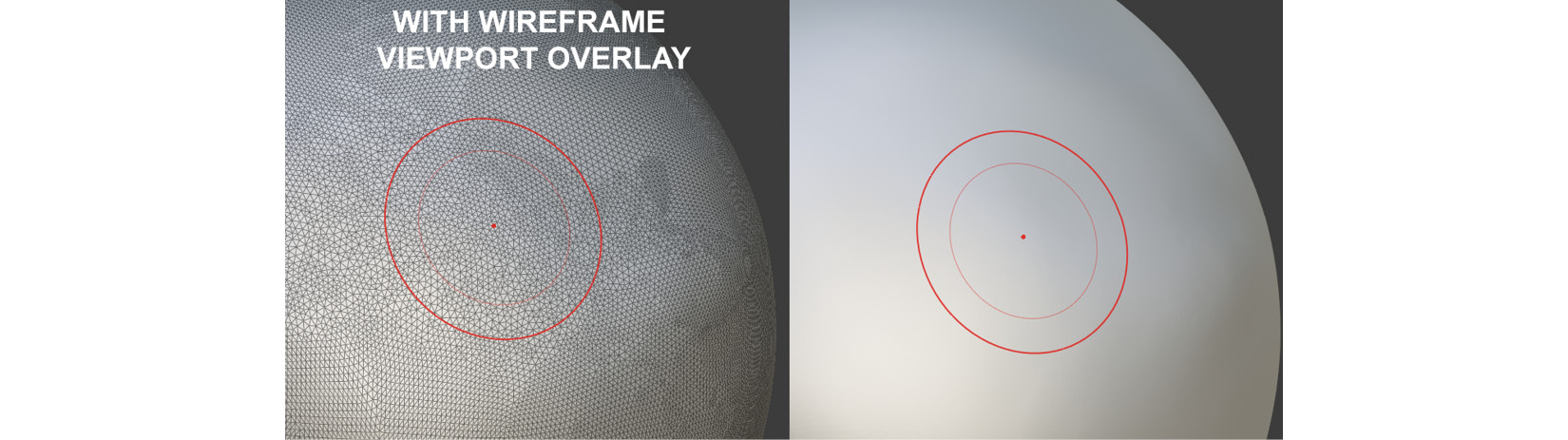
Figure 3.12 – (A) Brushing over the surface artifacts replaces them with small triangular faces;(B) Smoothing them out
You've just learned how to deal with mesh surface artifacts. Now, let's start sculpting on the rest of the Alien Plant.
Adding secondary and tertiary forms
Now that the basic shape of the Alien Plant is complete, let's add some more details (called secondary forms in sculpting) to the upper parts of the Alien Plant:
- Before we get started on the secondary forms, let's smooth the shading on the model. Make sure the Alien Plant model is selected, then switch to the Layout Workspace tab. Right-click anywhere in the 3D Viewport and select Shade Smooth from the menu that opened. Now, return to the Sculpting Workspace area.
- Zoom into the upper part of the main trunk. Here, the plant has alien-like spore sacks that grow around the tops.
- Select the Inflate brush from the toolbar and set Brush Strength to 0.85.
- Gently brush in a circular motion until dome-like shapes form on the mesh's surface, as shown in the following screenshot. Continue sculpting more of these around the head and then move on to the other three plant heads. Try to cluster some of these domes together and keep some domes spaced apart. Vary the sizes of these domes. This will create an organic look; if you space them too evenly with uniform size, they will appear too mechanical:
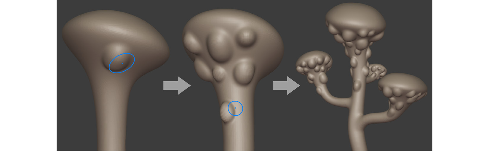
Figure 3.13 – Adding spore sacks to the Alien Plant
With that, you've learned how to use the Inflate brush to add dome-like details over a mesh surface. Now, let's learn how to use masking to quickly add some interesting details.
Using masking in 3D sculpting
The effect of masking in 3D sculpting is to define an area of the mesh that stops us from making modifications to it. Using masking in combination with other sculpting tools gives us a lot of new ways to deform a mesh.
Let's learn how to affect a whole area of a mesh globally (all at once) without the need to brush the surface:
- Select the Mask brush since we want to mask out areas of the mesh.
- Set Brush Strength to 1 and Brush Radius to 15.
- Mask around the shapes of the domes, without brushing over them. Continue the mask around the plant heads. Mask the tops by using a bigger Brush Radius.
- Once you've completed all four of the Alien Plant's heads, press Ctrl + I to use the Invert Mask function. You can see what the inverted mask looks like in Figure 3.14, right-hand side.
We used the mask in this way because it was quicker to paint the mask on the smaller surface area and then invert it, rather than to paint the mask over the bigger surface area:
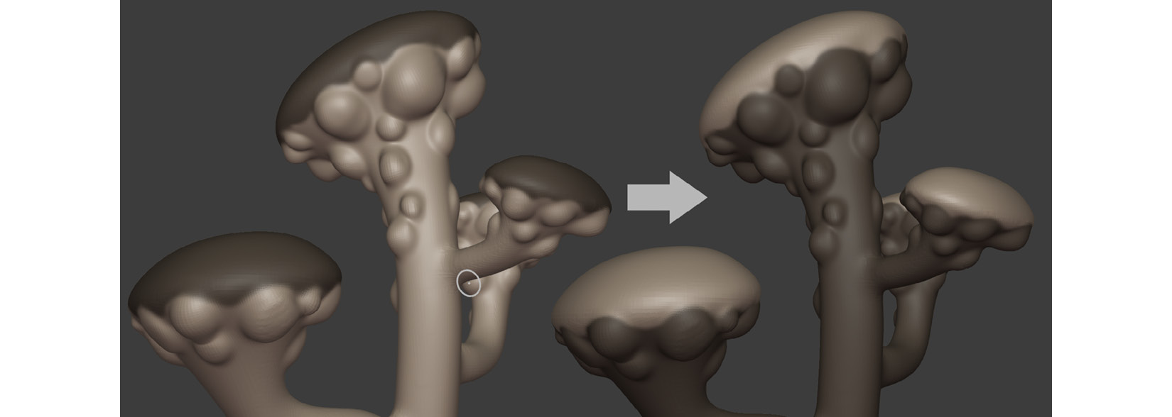
Figure 3.14 – (Left) Painting masks; (Right) Inverting the masks
Now, let's inflate parts of the mesh evenly but leave the masked parts alone.
- Select the Mesh Filter tool from the toolbar. This will apply an effect (of your choosing) over the entire mesh or the parts of it that have not been hidden or masked.
- From the Header bar, next to Filter Type, select Inflate from the drop-down menu.
- Left-click on a space inside the 3D Viewport (but not on a menu) and drag the mouse to the right to apply the Mesh Filter effect. The further you drag your mouse to the right, the stronger the applied effect will be, as shown in Figure 3.15, part A:

Figure 3.15 – (A) Using Mesh Filter to inflate the unmasked parts of the mesh;(B) Smoothing the sharp edges
- After you've inflated the mesh, as shown in Figure 3.15, part A, press Alt + M to apply the Clear Mask function. The model with the cleared mask should now look like the model shown in Figure 3.15, part B.
- Use the Smooth brush with a low Strength setting and smooth out the sharp edges around all four plant heads.
- Paint masks in the shape of big dots on all four plant heads.
- Press Ctrl + I to apply the Invert Mask function.
- Use the Mesh Filter tool to inflate the dots, but in the negative direction, so that the dots are going into the mesh instead of inflating outwards.
- Press Alt + M to apply the Clear Mask function.
- Smooth the edges of the submerged dots, as shown in Figure 3.16, part C:
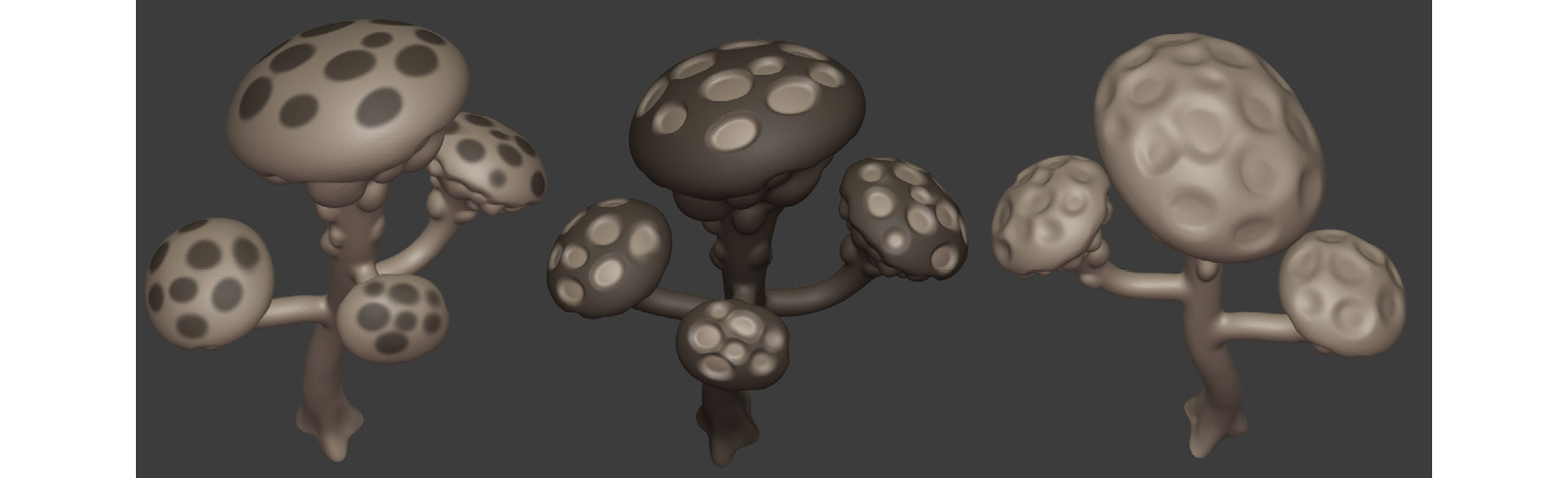
Figure 3.16 – (A) Painting the masks;(B) Inverting the mask and using the Inflate Mesh filter in the negative direction;(C) Smoothing the sharp edges
In this section, you learned how to use masking in combination with the Mesh Filter tool to affect the mesh in unmasked areas.
The Alien Plant's surface is starting to look interesting and organic. If you look at the provided Alien Plant reference image, you will notice there are small nodules (protrusions) on the top of the plant's heads. These nodules release the spores from the spore sacks into the Alien-Planet's atmosphere.
Handy Tip
To spark your creativity while you are working on your 3D assets, it is useful to come up with an interesting backstory for your models, characters, and movie sets. Having a backstory allows your projects to come to life and be much more believable since they're filled with vivid details.
In the next section, you will learn how to sculpt the nodules in the Alien Plant model.
Sculpting the spore nodules
For this task, we will use the Inflate brush again, but this time on the inside of each of the recessed spots that you made in the previous section. Make sure that some of the nodules are more inflated than others and have varying sizes:
- Once all the nodules have been inflated, remesh your sculpture with Voxel Size set to anywhere between 0.01 and 0.03.
- Use the Draw brush and hold Ctrl while sculpting to push in the centers of some of the nodules, as shown in Figure 3.17, part C:
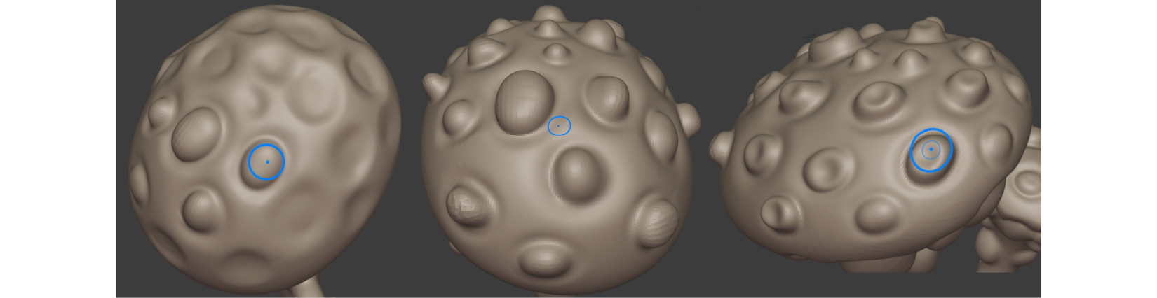
Figure 3.17 – (A) Sculpting the nodules; (B) Inflating the nodules;(C) Pushing in the center parts
Your Alien Plant sculpture should now look similar to the following:

Figure 3.18 – The Alien Plant sculpture's progress thus far
In this section, you practiced how to sculpt some extra details inside the mesh. In the next section, we will start adding the final polish.
Adding the final polish to the sculpture
The Alien Plant looks great so far, so let's sculpt the finishing touches!
In terms of sculpting terminology, we call the small fine details such as fine wrinkles, pores, and surface grooves the tertiary details. Let's add these now:
- Select the Draw Sharp brush and set Strength to 0.5.
- On one of the plant heads, gently start outlining one of the dome-like spore sacks that you sculpted previously. These sharper lines add an extra layer of visual detail. Without these, everything would look too smooth.
- Continue to outline the rest of the spore sacks. The following screenshot shows how the spore sacks on the left-hand side look quite smooth, while they look sharp and defined on the right-hand side:
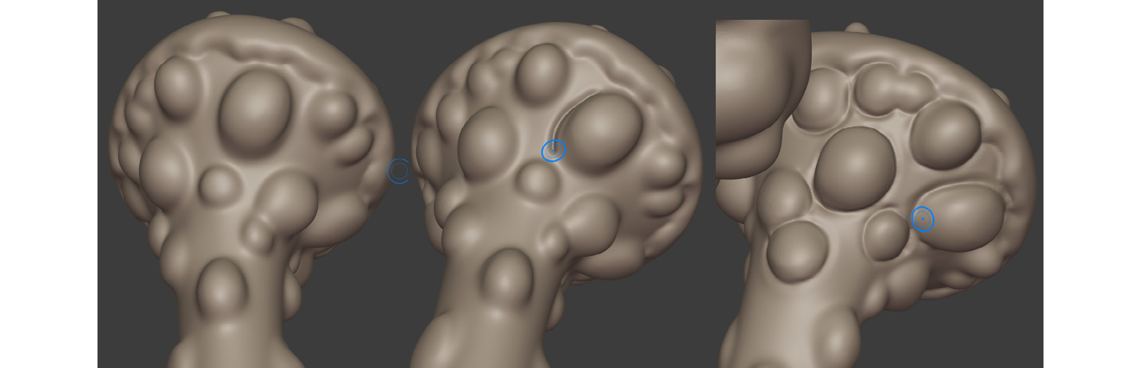
Figure 3.19 – Adding sharp creases with the Draw Sharp brush
- Once all the spore sacks are completed, it is time to do the same thing to the spore nodules on the tops of all the plant heads. The result should resemble the model on the right in the following screenshot:
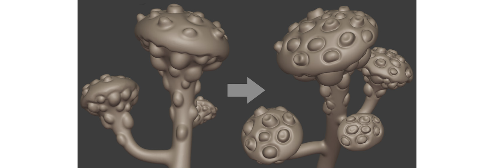
Figure 3.20 – Adding sharp creases with the Draw Sharp brush to the spore nodules
- The last step is to add some more lines to the trunk and branches. These lines will balance all the details and create visual cohesion. Use the Draw Sharp brush (with the same settings you used previously) and sculpt some fine lines of varying depth and lengths that follow the direction of the trunk and branches, as shown in the following screenshot:
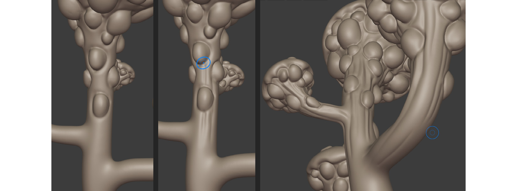
Figure 3.21 – Adding sharp creases to the trunk and branches with the Draw Sharp brush
You have just completed your first sculpture in Blender! Your model should now resemble the Alien Plant shown in the following screenshot:
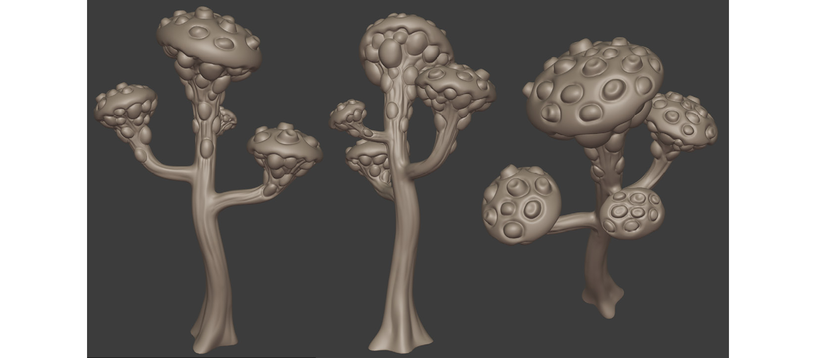
Figure 3.22 – The Alien Plant sculpt completed
Save the Alien Plant model in Blender file format (.blend). You also need to export this high-poly Alien Plant model so that you can use it in the tutorial in Chapter 4, UV Maps and Texture Baking. Navigate to File | Export | Wavefront (.obj) and use the settings shown in Figure 3.20.
In the File Name entry box, choose a suitable filename for the exported file. Export this high-poly model and use the .obj model format:
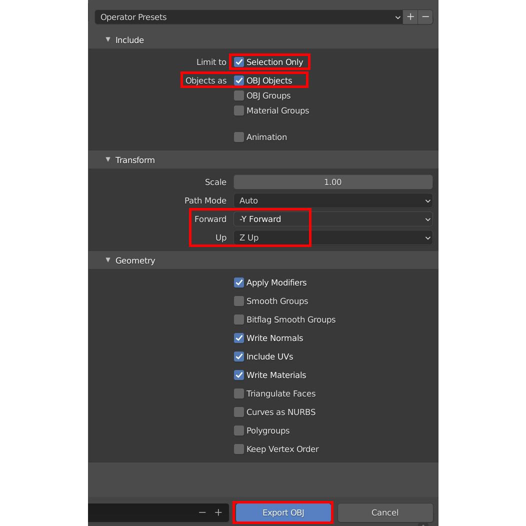
Figure 3.23 – Exporting your model using the Wavefront (.obj) settings
In this section, you learned how to add the finishing touches to the model by using the versatile Draw Sharp brush.
Congratulations! By completing all the practical 3D sculpting sections in this chapter, you have acquired a clear understanding of the entire sculpting pipeline: you know which brushes to use for different tasks and how to fix problem areas if they occur.
Now that the sculpt of the Alien Plant has been completed, we need to convert this model into a mesh that UE can use.
At this stage, the sculpt is too high-resolution to be used as an animated model in UE. This is because the denser the geometry is in a mesh, the more of your computer's computational power (CPU) it needs to deform that mesh (at the time of writing, a regular desktop PC's CPU is not powerful enough to deform a very dense mesh in real time). That is why we need to create a low-resolution mesh for animation purposes.
I will take you through the steps to convert our model into a lower-resolution mesh in the next section.
Generating the low-resolution mesh
To prepare the sculpted mesh for UE, we need to create a new mesh that has the same shape as the high-resolution mesh. However, the new mesh should be low-resolution in geometric density (also called a low-polygon mesh). The process of creating a low-resolution mesh is called retopology.
There are many ways to do retopology in Blender. The most accurate methods are all done by hand (manual retopology). They provide superior results, but these techniques are beyond the scope of this book.
I will show you how to perform retopology using a method called auto-retopology (automatically generated by a software algorithm). It is one of the simplest ways you can automatically generate a new low-resolution mesh. It is not as accurate, but the main benefits are simplicity and great savings in terms of production time.
We will use the free standalone software known as Instant Meshes (the download link has been provided in the Technical requirements section). In my experience, it has superior results compared to the built-in auto-retopology tools that are included in Blender.
The first step is to reduce our current mesh's geometric density with a modifier in Blender since Instant Meshes work better when the source mesh is low resolution.
In the next section, we will learn how to use the Decimate modifier in Blender.
Decimating the mesh in Blender
The Decimate modifier uses a function that decimates a mesh. Decimation reduces the mesh's geometry by converting the surface into triangular faces that are of lower resolution than the original mesh.
You may be wondering, why not just use this function to create a low-resolution mesh for UE? The answer is that the topology (the layout of the faces and edges) of the surface is not suited for a model that needs to be animated, plus there could be many smoothing artifacts on the mesh.
Let's decimate the mesh in Blender:
- Switch to Object Mode and go to Layout Workspace.
- Look under your Modifiers list and find the Decimate modifier.
- When you look at this modifier in the Properties panel, you will see that the mesh still looks the same. This is because the ratio figure needs to be adjusted.
- Change the default Ratio to 0.03. You will notice that the mesh's geometric density is greatly reduced (decimated), as shown in the following screenshot:
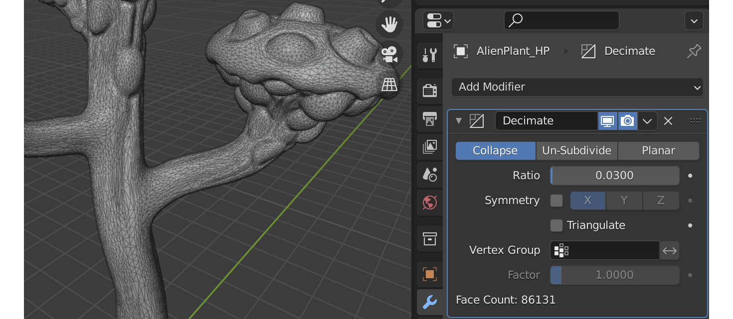
Figure 3.24 – Using the Decimate modifier to reduce mesh density for instant meshes
- Navigate to File | Export | Wavefront (.obj). This will export the model as a .obj model. The reason we're using the .obj file format is that the Instant Meshes software can only load .obj and .ply types of model formats.
- Use the settings shown in Figure 3.23. In the File Name entry box, choose a suitable filename for the exported file. This decimated version of the model will only be used in Instant Meshes.
In this section, you learned how to use the Decimate modifier to reduce the mesh's geometric density for exporting to Instant Meshes.
In the next section, you will learn how to use Instant Meshes for auto-retopology.
Using Instant Meshes for auto-retopology
Instant meshes is a free software tool that can be used to generate auto-retopology meshes from your source mesh. You can guide this auto-retopology algorithm by drawing guidelines (called Orientation Comb Lines in Instant Meshes).
Note
The controls for Instant Meshes are rotate: left mouse button, pan: right mouse button, and zoom: use the mouse wheel.
Let's use the Alien Plant model in Instant Meshes:
- Launch the Instant Meshes software.
- Click on the Open mesh button and load the decimated version of your Alien Plant model that you've just exported (the .obj mesh).
- Change Target Vertex Count to approximately 18K.
- Position your mesh so that you can see the whole mesh at once.
- Click on the Orientation Comb icon, as shown in Figure 3.25, part A. When Orientation Comb is active, the viewport navigation will be locked in place until you unclick the Orientation Comb icon. The Orientation Comb function creates orientation comb lines (directional guidelines) that tell the software how to direct the flow of the Edge Loops in the direction that you are combing over the mesh's surface.
- Draw orientation comb lines by using your mouse cursor. First, left-click + drag a line across the surface of the mesh, as shown in Figure 3.25, part A. When you let go of the mouse button, a colored line will appear with a little X icon on it, as shown in Figure 3.25, part B.
You will notice that multiple colored surface lines will appear all over your mesh's surface. These colored lines are a visual representation of the Edge Flow, as shown in Figure 3.26:
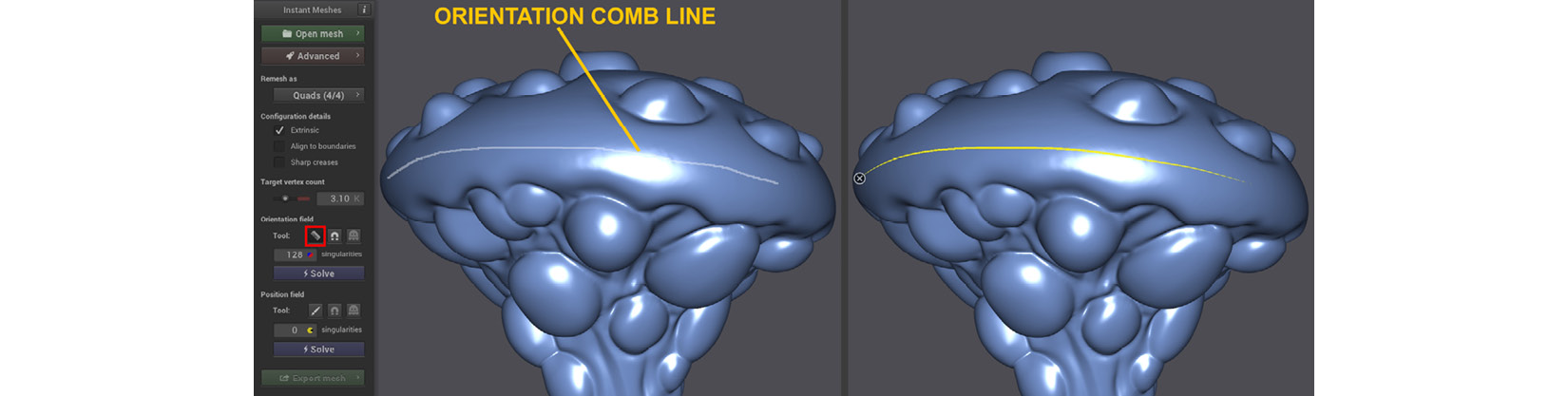
Figure 3.25 – (A) Drawing an orientation comb line across the surface of the model; (B) The orientation comb line becomes a colored line
- We are trying to change the Edge Flow of the Edge Loops to make it easier to animate and to UV Map later. In Figure 3.26, part A, I have highlighted a part of a mesh where the default Edge Flow was not flowing correctly. In Figure 3.26, part B, I have drawn multiple orientation comb lines over the mesh's surface to adjust the Edge Flow. The following screenshot shows how much more organized the Edge Flow is now:
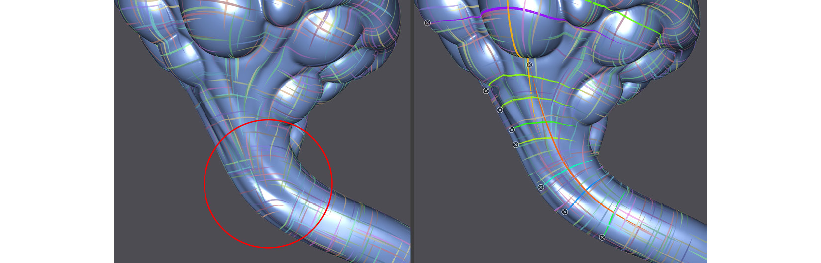
Figure 3.26 – (A) The Edge Flow was disorganized in the highlighted area;(B) I have drawn multiple orientation comb lines to fix the Edge Flow
- If you want to delete a line, click on the little X icon.
- When you've finished drawing guidelines from your current viewing angle, unclick the Orientation Comb icon and rotate your view to a new angle. Re-enable Orientation Comb to start the guidelines again.
- Continue this process of rotating and drawing guidelines until your guidelines look similar to what is shown in the following screenshot.
- Press the Solve button under the Orientation Field heading. You will see colored lines appear all over your mesh:
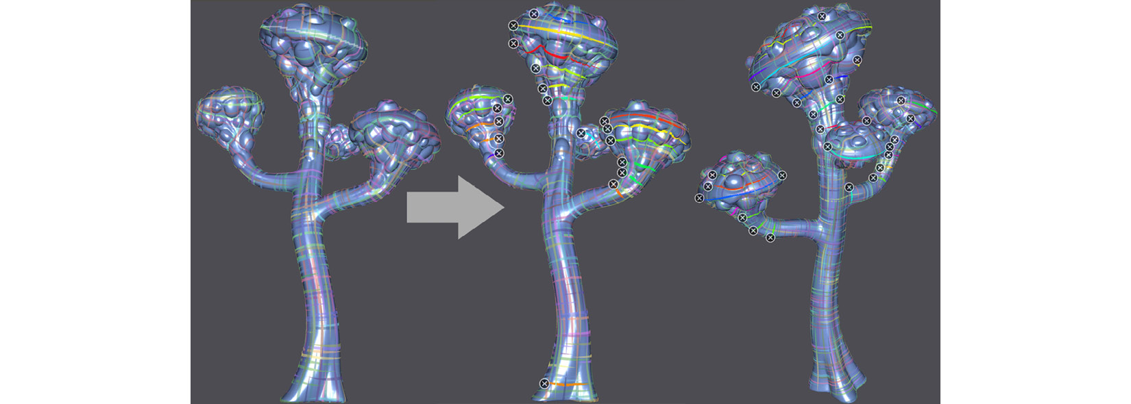
Figure 3.27 – Creating guidelines with Orientation Comb
- Disable the Orientation Comb option.
- Look for the Solve button under the Position Field heading and click it. The mesh display will turn dark blue with light blue edge lines.
- Click on the Export mesh button. Another menu will appear to the right of the current menu.
- Click on the Extract mesh button to see your generated mesh appear. It will have a red wireframe and blue-colored faces. Your mesh should look similar to what's shown in the following screenshot.
- Click on Save... and save the new mesh to your hard disk. This will save your model in the .obj file format:
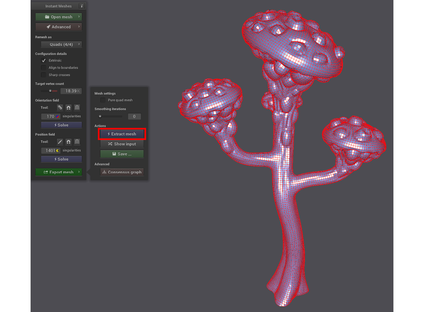
Figure 3.28 – The retopology mesh generated with Instant Meshes
You now have a thorough understanding of how to use Instant Meshes to create auto-retopology for your models.
Congratulations! You've just completed the process of sculpting a model in Blender and generating the retopology mesh!
Summary
In this chapter, you learned how to put Blender's 3D sculpting toolset to great practical use by sculpting an organic Alien Plant model to use as a set piece for our 3D movie.
You also learned how to follow the reference image to create the block-out model.
After that, you learned how to refine that shape by adding geometry and sculpting finer details. We briefly delved into fixing problem areas and how to use masking as a useful tool in 3D sculpting.
Finally, you learned how to take this sculpted model and convert it into the low-resolution mesh that we will use in UE5.
In the next chapter, we will explore how and why a model needs to be UV mapped and how to bake texture maps to use them in our texturing tutorial in a later chapter.