
In this recipe, we will learn how to create a point cloud based on an image selected by the user. We will create a grid of points where each point will correspond to a pixel. The x and y coordinates of each point will be equal to the pixel's position on the image, and the z coordinate will be calculated based on its color.
Include the necessary files to work with OpenGL, image surfaces, VBO meshes, and loading images.
Add the following code to the top of the source file:
#include "cinder/gl/gl.h"
#include "cinder/Surface.h"
#include "cinder/gl/Vbo.h"
#include "cinder/MayaCamUI.h"
#include "cinder/ImageIo.h"
Also, add the following using statements:
using namespace ci;
using namespace ci::app;
using namespace std;
We will learn how to read pixel values from an image and create a point cloud.
- Declare
ci::Surface32fto store the image pixels,ci::gl::VboMeshthat we will use as the point cloud, andci::MayaCamUIfor easy rotation of our scene.Surface32f mImage; gl::VboMesh mPointCloud;gl::VboMesh mPointCloud; MayaCamUI mCam;
- In the
setupmethod, we will first open a file load dialog and then let the user select the image to use and check if it returns a valid path.fs::path imagePath = getOpenFilePath( "", ImageIo::getLoadExtensions() ); if( imagePath.empty() == false ){ - Next, let's load the image and initialize
mPointCloud. We will set theci::gl::VboMesh::Layoutto have dynamic positions and colors so that we will be able to change them later.mImage = loadImage( imagePath ); int numPixels = mImage.getWidth() * mImage.getHeight(); gl::VboMesh::Layout layout; layout.setDynamicColorsRGB(); layout.setDynamicPositions(); mPointCloud = gl::VboMesh( numPixels, 0, layout, GL_POINTS );
- Next, we'll iterate over the image's pixels and update the vertices in
mPointCloud.Surface32f::IterpixelIt = mImage.getIter(); gl::VboMesh::VertexItervertexIt( mPointCloud ); while( pixelIt.line() ){ while( pixelIt.pixel() ){ Color color( pixelIt.r(), pixelIt.g(), pixelIt.b() ); float height = color.get( CM_RGB ).length(); float x = pixelIt.x(); float y = mImage.getHeight() - pixelIt.y(); float z = height * 100.0f; vertexIt.setPosition( x,y, z ); vertexIt.setColorRGB( color ); ++vertexIt; } } - Now we will set up the camera so that it will rotate around the center of the point cloud and close the
ifstatement we began on the second step.Vec3f center( (float)mImage.getWidth()/2.0f, (float)mImage.getHeight()/2.0f, 50.0f ); CameraPersp camera( getWindowWidth(), getWindowHeight(), 60.0f ); camera.setEyePoint( Vec3f( center.x, center.y, (float)mImage.getHeight() ) ); camera.setCenterOfInterestPoint( center ); mCam.setCurrentCam( camera ); } - Let's declare and implement the necessary mouse event handlers to use
mCam.void mouseDown( MouseEvent event ); void mouseDrag( MouseEvent event );
- And implement them:
void MyApp::mouseDown( MouseEvent event ){ mCam.mouseDown( event.getPos() ); } void MyApp::mouseDrag( MouseEvent event ){ mCam.mouseDrag( event.getPos(), event.isLeft(), event.isMiddle(), event.isRight() ); } - In the
drawmethod, we will begin by clearing the background, setting the window's matrices defined bymCam, and enable reading and writing the depth buffer.gl::clear( Color( 0, 0, 0 ) ); gl::setMatrices( mCam.getCamera() ); gl::enableDepthRead(); gl::enableDepthWrite();
- Finally, we will check if
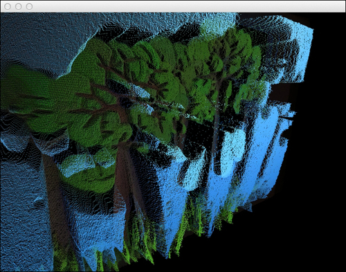
mPointCloudis a valid object and draw it.if( mPointCloud ){ gl::draw( mPointCloud ); } - Build and run the application. You will be prompted with a dialog box to select an image file. Select it and you will see a point cloud representation of the image. Drag the mouse cursor to rotate the scene.
We started by loading an image into ci::Surface32f. This surface stores pixels as float numbers in the range from 0 to 1.
We created a grid of points where the x and y coordinates represented the pixel's position on the image and the z coordinate was the length of the color's vector.
The point cloud is represented by a ci::gl::VboMesh, which is a mesh of vertices, normal, colors, and indexes with an underlying Vertex Buffer Object. It allows for optimized drawing of geometry.