
Chapter 14. Data Acquisition Software
14.1. An Overview of DA&C Software
In addition to code that acquires data or issues control signals, it is usual for DA&C (data acquisition and control) software to incorporate a number of support modules that allow the system to be configured and maintained. Other routines may be required for sorting, analyzing, and displaying the acquired data. A typical DA&C program may contain the following modules and facilities:
- Program configuration routines
- Diagnostics modules
- System maintenance and calibration modules
- Run-time modules
- Device drivers
- Data analysis modules
With the exception of device drivers, these modules are executed more or less independently of each other (although it is, of course, possible for multitasking systems to execute two or more concurrently). A brief overview of the main software components of a typical DA&C system follows. Particular systems may, of course, differ somewhat in the detail of their implementation but most applications will require at least some of these modules.
14.1.1. Program Configuration Routines
These software routines may be used for initial configuration of elements of the system that the end user would normally never (or very infrequently) have to change. This might include facilities for selecting and setting up hardware and driver options; for specifying how data is to be routed through software “devices” (such as comparators, triggers, data-scaling operators, software latches, logical operators, or graphical displays); for defining start, stop, and error conditions; or for selecting delays, run times, and data buffer sizes.
14.1.2. Diagnostic Modules
Once a DA&C program has been tested and debugged, any diagnostic routines that the designer may have included for testing are often removed or disabled. However, their value should not be underestimated in “finished” (i.e., operational) systems. Routines such as these can be invaluable tools during installation and for subsequent system maintenance. Often, the dynamic and transient nature of input/output (I/O) signals and the complex interrelation between them can make it very difficult to reproduce a fault during static testing with a voltmeter, continuity tester, or a logic probe. Well-designed diagnostic routines can be a great benefit to maintenance engineers should a fault occur somewhere in the DA&C system.
With a little care and thought it is usually quite straightforward to implement a range of simple but useful diagnostic routines. These can be made to monitor aspects of the DA&C system either during normal operation or when the system is placed in a special test mode. On the simplest level, the diagnostic routines might check for incorrect hardware or software configuration. They might also be designed to perform continuous tests during normal operation of the system. This might include checking for interruptions in communication between system components, ensuring correct timing of I/O control signals, and monitoring or validating data from individual sensors.
Diagnostic software routines have their limitations, however, and other means of fault finding must be used where appropriate. Various items of test equipment such as voltmeters, logic probes, and logic pulsers may also be needed. More sophisticated equipment is sometimes required, especially when dealing with rapid pulse trains. Digital storage, or sampling, oscilloscopes allow high-frequency waveforms to be captured and displayed. These are especially suited to monitoring digital signals on high-speed parallel buses or serial communications links. Where it is necessary to see the relationship between two or more time-varying signals, logic analyzers may be used. These devices possess multiple (typically 32) probes, each of which detects the logic state of some element of the digital I/O circuit under test. Logic analyzers are controlled by a dedicated microcomputer and can be programmed to provide a snapshot of the logic states present at the probes on a display screen. The conditions for triggering the snapshot—that is, a selected pattern of logic states—can be programmed by the user. The device may also be used for timing analysis, in which case it operates in a similar way to a multiple-beam oscilloscope.
In addition to these items of equipment, purpose-built test harnesses may be used in conjunction with diagnostic software. Test harnesses may consist of relatively simple devices such as a bank of switches or LEDs that are used to check the continuity of digital I/O lines. At the other extreme a dedicated computer system, running specially designed test software, may be required for diagnosing problems on complex DA&C systems. See Section 14.4.1, Software Production and Testing, later in this chapter for more on this topic.
14.1.3. System Maintenance and Calibration Modules
Tasks such as calibrating sensors, adjusting comparators, and tuning control loops might need to be carried out periodically by the user. Because any errors made during calibration or control loop tuning have the potential to severely disrupt the operation of the DA&C system, it is essential for the associated software routines to be as robust and simple to use as possible.
One of the most important of these system maintenance tasks is calibration of analog input (i.e., sensor) channels. Many sensors and signal-conditioning systems need to be recalibrated periodically in order to maintain the system within its specified operating tolerance. The simplest approach (from the program designer's perspective) is to require the user to manually calculate scaling factors and other calibration parameters and then to type these directly into a data file and so forth. It goes without saying that this approach is both time consuming and error prone. A more satisfactory alternative is to provide an interactive calibration facility that minimizes the scope for operator errors by sampling the sensor's input at predefined reference points, and then automatically calculating the required calibration factors. We will resume our discussion of this subject in Chapter 15 which covers scaling and interactive calibration techniques in some detail.
14.1.4. Run-Time Modules
These, together with the device drivers, form the core of any DA&C system. They are responsible for performing all of the tasks required of the system when it is “live”—such as reading sensor and status inputs, executing control algorithms, outputting control signals, updating real-time displays, or logging data to disk.
The nature of the run-time portion varies immensely. In some monitoring applications, the run-time routine may be very simple indeed. It might, for example, consist of an iterative polling loop that repeatedly reads data from one or more sensors and then perhaps stores the data in a disk file or displays it on the PC's screen. In many applications other tasks may also have to be carried out. These might include scaling and filtering the acquired data or executing dynamic control algorithms.
More complex real-time control systems often have very stringent timing constraints. Many interrelated factors may need to be considered in order to ensure that the system meets its real-time response targets. It is sometimes necessary to write quite elaborate interrupt-driven buffered I/O routines or to use specially designed real-time operating systems (RTOSs) in order to allow accurate assessments of response times to be made. The software might be required to monitor several different processes in parallel. In such cases, this parallelism can often be accommodated by executing a number of separate program tasks concurrently. We will discuss concurrent programming later in this chapter.
14.1.5. Drivers
A diverse range of data-acquisition units and interface cards are now on the market. The basic functions performed by most devices are very similar, although they each tend to perform these functions in a different manner. The DA&C system designer may choose from the large number of analog input cards that are now available. Many of these will, for example, allow analog signals to be digitized and read into the PC, but they differ in the way in which their software interface (e.g., their control register and bit mapping) is implemented.
To facilitate replacement of the data-acquisition hardware, it is prudent to introduce a degree of device independence into the software by using a system of device drivers. All I/O is routed through software services provided by the driver. The driver's service routines handle the details of communicating with each item of hardware. The main program is unaware of the mechanisms involved in the communication: It only knows that it can perform I/O in a consistent manner by calling a well-defined set of driver services. In this way the data-acquisition hardware may be changed by the end user and, provided that a corresponding driver is also substituted, the DA&C program should continue to function in the same way. This provides some latitude in selecting precisely which interface cards are to be used with the software. For this reason, replaceable device drivers are commonplace in virtually all commercial DA&C programs. Protected operating systems such as Windows NT perform all I/O via a complex system of privileged device drivers.
14.1.6. Data Analysis Modules
These modules are concerned mainly with postacquisition analysis of data. This might include, for example, spectral analysis or filtering of time-varying signals, statistical analysis (including statistical process control, SPC), and report generation. Many commercial software packages are available for carrying out these activities. Some general-purpose business programs such as spreadsheets and graphics/presentation packages may be suitable for simple calculations and for producing graphical output, but there are a number of programs that cater specifically for the needs of scientists, engineers, and quality control personnel. Because of this, and the fact that the details of the techniques involved are so varied, it is impracticable to cover this subject in the present book. A variety of data reduction techniques are described by Press et al. (1992) and Miller (1993).
14.2. Data Acquisition and Control in Real Time
Data-acquisition systems that are designed for inspection or dimensional gauging applications may be required to gather data at only very low speeds. In these cases, the time taken to read and respond to a series of measurements may be unimportant. Because such systems usually have quite undemanding timing requirements, they tend to be relatively straightforward to implement. The choice of computing platform, operating system, and programming language is usually not critical. A surprisingly large number of industrial DA&C applications fall into this category. However, many do not.
High-speed DA&C normally has associated with it a variety of quite severe timing constraints. Indeed the PC and its operating systems cannot always satisfy the requirements of such applications without recourse to purpose-built hardware and/or special coding techniques. High-speed processors or intelligent interface devices may be required in order to guarantee that the system will be capable of performing certain DA&C operations within specified time limits.
A real-time DA&C system is one in which the time taken to read data, process that data, and then issue an appropriate response is negligible compared with the timescale over which significant changes can occur in the variables being monitored and/or controlled. There are other more precise definitions, but this conveys the essence of real-time data acquisition and control.
A typical example of a real-time application is a furnace control system. The temperature is repeatedly sampled and these readings are then used to control when power is applied to the heating element. Suppose that it is necessary to maintain the temperature within a certain range either side of some desired setting. The system detects when the temperature falls to a predefined lower limit and then switches the heating element on. The temperature then rises to a corresponding upper limit, at which point the monitoring system switches the heating element off again, allowing the temperature to fall. In this way, the temperature repeatedly cycles around the desired mean value. The monitoring system can only be said to operate in real time, if it can switch the heating element in response to changes in temperature quickly enough to maintain the temperature of the furnace within the desired operating band.
This is not a particularly demanding application—temperature changes in this situation are relatively slow—but it does illustrate the need for real-time monitoring and control systems to operate within predefined timing constraints. There are many other examples of real-time control systems in the process and manufacturing industries (such as control of reactant flow rate, controlling component assembly machines, and monitoring continuous sheet metal production, for example) which all have their own particular timing requirements. The response times required of real-time systems might vary from a few microseconds up to several minutes or longer. Whatever the absolute values of these deadlines, all real-time systems must operate to within precisely defined and specified time limits.
14.2.1. Requirements of Real-Time DA&C Systems
As mentioned previously, normal PC operating systems (DOS, Microsoft Windows, and OS/2) do not form an ideal basis for real-time applications. A number of factors conspire to make the temporal response of the PC somewhat unpredictable. Fortunately there are ways in which the situation can be improved. These techniques will be introduced later in this section, but first we will consider some of the basic characteristics that a real-time computer system must possess. In addition to the usual properties required of any software, a real-time system must generally satisfy the following requirements.
14.2.1.1. Requirement 1: High Speed
The most obvious requirement of a real-time system is that it should be able to provide adequate throughput rates and response times. Fortunately, many industrial applications need to acquire data at only relatively low speeds (less than 100 or 200 readings per second) and need response times upward of several tens of milliseconds. This type of application can be easily accommodated on the PC. Difficulties may arise when more rapid data acquisition or shorter responses are required.
Obviously a fast and efficient processor is the key to meeting this requirement. As we have already seen, modern PCs are equipped with very powerful processors which are more than adequate for many DA&C tasks. However, the memory and I/O systems, as well as other PC subsystems, must also be capable of operating at high speed. The disk and video subsystems are notorious bottlenecks, and these can severely limit data throughput when large quantities of data are to be displayed or stored in real time. Fortunately, most modern PC designs lessen this problem to some extent by making use of high-speed buses such as the small computer systems interface (SCSI) and the PCI local bus. Modern Pentium-based PCs are very powerful machines and are capable of acquiring and processing data at ever increasing rates. Older XT and 80286- or 80386-based computers offer a lower level of performance, but are still often adequate in less demanding applications.
14.2.1.2. Requirement 2: Determinism
A deterministic system is one in which it is possible to precisely predict every detail of the way in which the system responds to specific events or conditions. There is an inherent predictability to the sequence of events occurring within most computer programs, although the timing of those events may be more difficult to ascertain. A more practical definition of a deterministic system is one in which the times taken to respond to interrupts, perform task switches, and execute operating system services and the like are well known and guaranteed. In short, a deterministic system has the ability to respond to external events within a guaranteed time interval.
Determinism is an important requirement of all real-time systems. It is necessary for the programmer to possess a detailed knowledge of the temporal characteristics of the operating system and device drivers as well as of the DA&C program itself. This knowledge is an important prerequisite for the programmer to assess the worst-case response of the system and thus to ensure that it meets specified deadlines.
14.2.1.3. Requirement 3: High-Resolution Timekeeping and Pacing Facilities
In addition to being able to operate within given time constraints, it is important for most real-time systems to be able to precisely measure elapsed time. This ability is essential for the software to accurately schedule I/O operations and other tasks. Where data is acquired at irregular or unpredictable rates, it is particularly important to be able to time stamp readings and other events. An accurate timing facility is also an invaluable aid to fault finding in dynamic systems. The PC is equipped with a real-time clock and a set of timers which are useful for this purpose. The timers function by means of the PCs interrupt system and provide a powerful means of pacing a data-acquisition sequence or for generating precisely timed control signals.
14.2.1.4. Requirement 4: Flexible Interfacing Capability
It should be obvious that any data-acquisition and control system should be able to interface easily to sensors, actuators, and other equipment. This requirement covers not only the PC's physical interfacing capacity (i.e., the presence of appropriate plugs, sockets, and expansion slots), but also encompasses an efficient means of transferring data in and out of the computer.
The PC possesses a very flexible interfacing system. As mentioned previously, this is implemented by means of the standard ISA, EISA, MCA, or PCI expansion buses or PCMCIA slots. The PC also facilitates processor-independent high-speed I/O using techniques known as direct memory access (DMA) and bus mastering. These facilities give the PC the capability to interface to a range of external buses and peripherals (e.g., data-logging units, sensors, relays, and timers) via suitable adaptor cards. Indeed, adaptor cards for RS-232 ports and Centronics parallel ports, which can be used to interface to certain types of DA&C hardware, are an integral component of almost all PCs.
14.2.1.5. Requirement 5: Ability to Model Real-World Processes
It should also be apparent to the reader that the logical structure of a real-time DA&C system should adequately mirror the processes that are being monitored. As we shall see on the following pages, this requirement sometimes necessitates using a specially designed real-time operating system. In less demanding applications, however, such a step is unnecessary provided that due care is taken to avoid some of the pitfalls associated with standard “desktop” operating systems.
14.2.1.6. Requirement 6: Robustness and Reliability
Again, this is a rather obvious requirement but its importance cannot be overstated. A number of steps can be taken to maximize the reliability of both hardware and software. We will return to this issue later in this chapter.
14.2.2. Simple DA&C Systems
Some PC-based DA&C systems are fairly undemanding in regard to the detailed timing of I/O events. Many applications involve quite low-speed data logging, where samples and other events occur at intervals of several seconds or longer. In other cases a high average data-acquisition rate might be needed, but the times at which individual readings are obtained may not be subject to very tight restrictions. Often, only a single process (or a group of closely coupled processes) will have to be monitored and in these cases it is usually sufficient to base the run-time portion of a DA&C program on a simple polling loop as illustrated in Figure 14.1.
Figure 14.1. Schematic illustration of the structure of a typical DA&C program based on a simple polling loop.

This figure shows the sequence and repetitive nature of events that might occur in a simple single-task application. When some predefined start condition occurs (such as a keystroke or external signal), the program enters a monitoring loop, during which data is acquired, processed, and stored. The loop may also include actions such as generating signals to control external apparatus. The program exits from the loop when some desired condition is satisfied—that is, after a certain time has elapsed, after a predefined number of readings have been obtained, or when the user presses a key. In some cases, additional processing may be performed once the data-acquisition sequence has terminated.
There are, of course, many variations on this basic theme, but the essence of this type of program structure is that all processing is performed within a single execution thread. This means that each instruction in the program is executed in a predefined sequence, one after the other. There is no possibility that external events will cause parts of the program to be executed out of sequence. Any tasks that the computer does carry out in parallel with the execution of the program, such as responding to keystrokes, “ticks” of the inbuilt timer, or to other system interrupts, are essentially part of the operating system and are not directly related to the functioning of the DA&C program.
It should be noted that events such as a timer or keyboard interrupt will temporarily suspend execution of the DA&C program while the processor services the event (increments the time counter or reads the keyboard scan code). This means that the timing of events within the interrupted program will not be totally predictable. However, such a system is still considered to operate in real time if the uncertainty in the timing of the data-acquisition cycle is small compared with the timescales over which the monitored variables change.
14.2.3. Systems with More Stringent Timing Requirements
All real-time systems have precisely defined timing requirements. In many cases, these requirements are such that the system must be designed to respond rapidly to events that occur asynchronously with the operation of the program. In these cases, a simple polling loop may not guarantee a sufficiently short response time. The usual way to achieve a consistent and timely response is to use interrupts.
14.2.3.1. Interrupts
Interrupts are the means by which the system timer, the keyboard, and other PC peripherals request the processor's attention. When service is required, the peripheral generates an interrupt request signal on one of the expansion bus lines. The processor responds, as soon as possible, by temporarily suspending execution of the current program and then jumping to a predefined software routine. The routine performs whatever action is necessary to fulfill the request and then returns control to the original program, which resumes execution from the point at which it was interrupted.
Because an interrupt handling routine is executed in preference to the main portion of the program, it is considered to have a higher priority than the noninterrupt code. The PC has the capacity to deal with up to 15 external interrupts (8 on the IBM PC, XT, and compatibles) and each of these is allocated a unique priority. This prioritization scheme allows high-priority interrupts to be allotted to the most time-critical tasks. With appropriate software techniques, the programmer may adapt and modify the interrupt priority rules for use in real-time applications.
The PC is equipped with a very flexible interrupt system, although the gradual evolution of the PC design has left something to be desired in terms of the allocation of interrupts between the processor and the various PC subsystems. When using interrupts, you should bear in mind two important considerations (although there are many others): reentrance and interrupt latency. These topics are introduced next.
14.2.3.2. Reentrant Code and Shared Resources
This is relevant to all types of software, not just to real-time DA&C programs. Because external interrupts occur asynchronously with the execution of the program, the state of the computer is undefined at the time of the interrupt. The interrupt handling routine must, therefore, ensure that it does not inadvertently alter the state of the machine or any software running on it. This means that it must (a) preserve all processor registers (and other context information) and (b) refrain from interfering with any hardware devices or data to which it should not have access. The last requirement means that care should be taken when calling any subroutines or operating system services from within the interrupt handler. If one of these routines happened to be executing at the time that the interrupt occurred, and the routine is then reentered from within the interrupt handler, the second invocation may corrupt any internal data structures that the routine was originally using. This can obviously cause severe problems—most likely a system crash—when control returns to the interrupted process. Of course, software routines can be written to allow multiple calls to be made in this way. Such routines are termed reentrant.
Unfortunately most MS-DOS and PC-DOS services are not reentrant, and so calls to the operating system should generally be avoided from within interrupt handlers. Specially designed real-time operating systems are available for the PC and these normally incorporate at least partially reentrant code. The run-time libraries supplied with compilers and other programming tool kits may not be reentrant. You should always attempt to identify any nonreentrant library functions that you use and take appropriate precautions to avoid the problems just outlined. A similar consideration applies when accessing any system resource (including hardware registers or operating system or BIOS data) that may be used by the main program and/or by one or more interrupt handlers.
14.2.3.3. Interrupt Latencies
This consideration is more problematic in real-time systems. The processor may not always respond immediately to an interrupt request. The maximum time delay between assertion of an interrupt request signal and subsequent entry to the interrupt handler routine is known as the interrupt latency. The length of the delay depends upon the type of instructions being executed when the interrupt occurs, the priority of the interrupt relative to the code currently being executed, and whether or not interrupts are currently disabled. Because interrupts are asynchronous processes, the effect of these factors will vary. Consequently, the delay in responding to an interrupt request will also vary. In order to ensure that the system is able to meet specified real-time deadlines, it is important for the system designer to quantify the maximum possible delay or interrupt latency.
By careful design it is possible to ensure that the code within a DA&C program does not introduce excessive delays in responding to interrupts. However, most programs occasionally need to call operating system or BIOS services. The programmer must ensure that the system will still respond within a specified time, even if an interrupt occurs while the processor is executing an operating system service. Unfortunately, standard desktop operating systems such as DOS and Microsoft Windows are not designed specifically for real-time use. These operating systems generally exhibit quite long interrupt latencies (particularly Windows). Typical figures are in the order of 10–20 ms, although you should not place too much reliance on this value as it will vary quite considerably between applications. Unfortunately, interrupt latency data for Windows and MS-DOS is hard to come by. Such operating systems are known as nondeterministic.
The magnitude of the problem can be reduced if real-time operating systems are used. These operating systems are designed so as to minimize interrupt latencies. They are usually essential if latencies of less than about 1 ms are required. The interrupt latencies applicable to various parts of the RTOS are also generally documented in the operating system manual, allowing the programmer to ensure that the whole system is capable of meeting the required response deadlines.
14.2.4. Concurrent Processing
Systems monitored or controlled by real-time DA&C software often consist of a number of separate processes operating in parallel. If these processes are asynchronous and largely independent of each other, it may be very difficult to represent them adequately in a simple, single-threaded program. It is usually more convenient to model parallel processes within the computer as entirely separate programs or execution threads. This arrangement is illustrated in Figure 14.2 which shows three separate processes being executed in parallel (i.e., three separate instances of the single-task loop of Figure 14.1).
Figure 14.2. Schematic illustration of concurrent monitoring and control of parallel processes.

Ideally, each process would be executed independently by a separate computer. We can go some way toward this ideal situation by delegating specific real-time tasks to distributed intelligent data-logging or control modules. Many factory automation systems adopt this approach. Dedicated data-acquisition cards, with on-board memory buffers and an intrinsic processing ability, can also be used to provide a degree of autonomous parallel processing. Other parallel processing solutions are also available, but these generally involve the use of separate multiprocessing computer systems and, as such, are beyond the scope of this book.
The most common way of modeling parallel processes on the PC is to employ concurrent programming (or multitasking) techniques. Most modern PCs are equipped with 80386, 80486, or Pentium processors and these incorporate features that greatly facilitate multitasking. On single-processor systems such as the PC, concurrent execution is achieved by dividing the processor's time between all executing programs. The processor executes sections of each program (or task) in turn, switching between tasks frequently enough to give the impression that all tasks are being executed simultaneously. This technique is used in multitasking operating systems such as OS/2, Windows, and UNIX.
14.2.4.1. Scheduling
Clearly, there must be a set of rules governing how and when task switching is to occur. These rules must also define the proportions of time assigned to, and the priorities of, each program. The process of allocating execution time to the various tasks is known as scheduling and is generally the responsibility of the operating system. The basic principles of scheduling are quite straightforward although the details of its implementation are somewhat more complex.
There are several ways in which a task scheduler can operate. In a system with preemptive scheduling, the operating system might switch between tasks (almost) independently of the state of each task. In nonpreemptive scheduling, the operating system will perform a task switch only when it detects that the current task has reached a suitable point. If, for example, the current task makes a call to an operating system service routine, this allows the operating system to check whether the task is idle (e.g., waiting for input). If it is idle, the operating system may then decide to perform more useful work by allowing another process to execute. This makes for efficient use of available processor time, but, as it relies on an individual task to initiate the switch, it does allow poorly behaved tasks to hog the processor. This is obviously undesirable in real-time applications because it may prevent other processes from executing in a timely manner. Preemptive scheduling, on the other hand, provides for a fairer division of time between all pending processes, by making the operating system responsible for regularly initiating each task switch.
14.2.4.2. Task Switching, Threads, and Processes
Whenever the operating system switches between tasks, it has to save the current context of the system (including processor registers, pointers to data structures, and the stack), determine which task to execute next, and then reload the previously stored context information for the new task. This processing takes time, which in a real-time operating system should be as short as possible. Most multitasking “desktop” operating systems use the advanced multitasking features available on 80386 and later processors to implement a high degree of task protection and robust task switching. However, this type of task switching can be too time consuming for use in high-performance real-time systems.
Other operating systems, such as those designed for real-time use, minimize the switching overhead by allowing each process (i.e., executing program) to be divided into separate execution threads. Threads are independent execution paths through a process. They can generally share the same code and data areas (although they each tend to have their own stack segment) and are normally less isolated from each other than are individual processes in a multitasking system. There is also less context information to be saved and restored whenever the operating system switches between different threads, rather than between different processes. This reduces the amount of time taken to perform the context switch. Although not intended for hard real-time applications, Microsoft Windows NT supports multithreaded processes.
The term task is used somewhat loosely in the remainder of this chapter to refer to both processes and threads.
14.2.5. Real-Time Design Considerations: A Brief Overview
As mentioned previously many PC-based data-acquisition systems will not be required to operate within the very tight timing constraints imposed in real-time control applications. However, it is useful for programmers involved in producing any type of time-dependent application to have a basic understanding of the fundamentals of real-time design. Even if you do not plan to implement these principles in your own systems, the following introduction to the subject may help you to avoid any related potential problems.
14.2.5.1. Structure of Real-Time Multitasking Programs
A typical real-time system might consist of several tasks running in parallel. The division of processing between tasks will usually be assigned on the basis of the real-world processes that the system must model. Each task will often be assigned to a separate, and more or less independent, physical process.
A typical example is the control of a manufacturing process for producing rolled metal or polymer sheet. One task might be dedicated to monitoring and controlling product thickness. Another may be assigned to regulating the temperature to which the material is heated prior to being passed through the rollers. Yet another task could be used for periodically transferring thickness, temperature, and status information to the display. A similar arrangement is shown in Figure 14.3.
Figure 14.3. Conceptual structure of a typical real-time multitasking system.
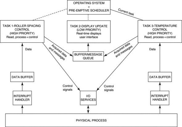
The interface between the various tasks and the data-acquisition hardware is often implemented by means of one or more interrupt handlers. These are normally contained within some form of dedicated device driver and are designed to allow the system to respond quickly to external events. Data acquired via an interrupt handler might be stored in a memory buffer until the associated task is able to read and process it. The individual tasks are responsible for operations such as data logging, display maintenance, or data reduction. A task might also be assigned to perform real-time calculations or tests on the acquired data. The results can then be used as the basis for generating control signals that are output to external equipment. In general, time-critical operations are performed by high-priority tasks, allowing them to take precedence over less critical operations such as managing the user interface.
There is generally a need for some form of intertask communication. This facility is often based on the use of message queues and memory buffers. Where shared memory or other resources are used, special protection mechanisms must be employed to mediate between tasks. Interprocess communication and protection mechanisms are provided by real-time operating systems (RTOSs). We will consider some of these facilities in more detail in the following sections. Additional information on real-time and multitasking systems can be found in the texts by Evesham (1990), Adamson (1990), Ben-Ari (1982) and Bell, Morrey, and Pugh (1992).
14.2.5.2. Accessing Shared Resources and Interprocess Communication
Although the processes in a multitasking system tend to operate more or less independently of each other, there usually has to be some degree of communication between them in order to transfer data or to synchronize certain features of their operation.
Interprocess communication involves accessing a shared resource such as a buffer or message queue that is maintained somewhere in the PC's memory. The operating system is generally responsible for coordinating access to these structures, and to other system resources such as disk drives and the like.
Whenever a task or an interrupt handler needs to access any shared resource—including hardware, operating system services, and data structures—great care must be taken to avoid conflicting with any other tasks that may be in the process of accessing the same resource. Consider a section of code that accesses a shared resource. If the code could possibly malfunction as a result of being preempted (or interrupted) by a task that accesses the same resource, the code is known as a critical section. It is necessary to protect critical sections from this type of interference by temporarily blocking task switches and/or interrupts until the critical section has been completed. This requirement is known as mutual exclusion.
Mutual exclusion can be enforced by means of semaphores. These are essentially flags or tokens that are allocated by the operating system to any process wishing to access a particular resource. A task may not proceed into a critical section until it has obtained the appropriate semaphore. In some systems, implementations of semaphores, for the purpose of enforcing mutual exclusion, are referred to as Mutexes.
14.2.5.3. Deadlocks and Lockouts
A deadlock occurs when all processes within a system become suspended as a result of each process waiting for another to perform some action. A lockout is similar but does not affect all tasks. It arises when conditions brought about by two or more processes conspire to prevent another process from running. Great care must be taken to avoid the possibility of deadlocks or lockouts in any real-time system.
14.2.5.4. Priorities
Many multitasking systems allow priorities to be assigned to the individual tasks. Whenever the scheduler performs a task switch, it uses the priorities assigned to each task to decide which one to execute next. This has the obvious benefit in real-time systems of allowing the most important or time-critical tasks to take precedence. In some systems, priorities can be changed dynamically. Priority systems can be quite complex to implement and a number of special programming techniques may have to be used, both within the application program and within the operating system itself, to ensure that the priorities are always applied correctly.
A common problem is priority inversion. If a low-priority task holds a semaphore and is then preempted by a higher-priority task that requires the same semaphore, the operating system will have to let the low-priority task continue to run until it has released the semaphore. If, meanwhile, the low-priority task is preempted by a task with an intermediate priority, this will run in preference to the highest-priority task. Some of the solutions to priority inversion (such as priority inheritance which dynamically alters the priority of tasks) raise additional problems. Certain RTOSs go to great lengths to provide generally applicable solutions to these problems. However, many of these difficulties can be avoided if the programmer has a detailed understanding of all of the software components running on the system so that potential deadlocks or other incompatibilities can be identified.
14.3. Implementing Real-Time Systems on the PC
Thanks to its expansion bus and flexible interrupt system, the PC has a very open architecture. This allows both hardware and software subsystems to be modified and replaced with ease. Although this openness is a great benefit to designers of DA&C systems, it can introduce problems in maintaining the system's real-time performance. If non-real-time code is introduced into the system, in the form of software drivers that trap interrupts or calls to operating system services, it may no longer be possible to guarantee that the system will meet its specified real-time targets. It should be clear that there is a need to exercise a considerable degree of control over the software subsystems that are installed into the PC.
In general, the architecture of the PC itself is reasonably well suited to real-time use. Its operating system is often the limiting factor in determining whether the PC can meet the demands of specific real-time applications. Standard MS-DOS or PC-DOS, Microsoft Windows, and the PC's BIOS present a number of difficulties that may preclude their use in some real-time systems. However, there are several specially designed real-time operating systems, including real-time versions of DOS and the BIOS, that can help to alleviate these problems. Real-time operating systems can be quite complex, and different implementations vary to such a degree that it is impracticable to attempt a detailed coverage here. The reader is referred to manufacturer's literature and product manuals for details of individual RTOSs.
As we have already noted, standard desktop operating systems (e.g., MS-DOS and Microsoft Windows) were not designed specifically for real-time use. Interrupt latencies and reentrance can be problematic. These operating systems frequently embark on lengthy tasks, which can block interrupt processing for unacceptable (and possibly indeterminate) lengths of time. Some of the instructions present on 80386 and subsequent processors, which were designed to facilitate multitasking (and which are used on systems such as Windows, OS/2, and UNIX), are not interruptible and can occupy several hundred processor cycles. Using these operating systems and instructions can increase interrupt latencies to typically several hundred microseconds or more.
Table 14.1 lists a few example applications that require different degrees of timing precision and different sampling rates. Notice that, where timing constraints are more relaxed, nondeterministic operating systems such as Windows may be used in conjunction with slow software-controlled DA&C hardware. Tighter timing constraints (near the bottom of the table) necessitate the use of buffered DA&C cards, hardware triggering, autonomous data loggers, or specialized RTOSs. Note that the timing figures and sampling rates listed in the table are intended only as a rough guide and in reality may vary considerably between applications.
Table 14.1. DA&C applications representative of various timing regimes
| Application | Approx. sampling rate (samples s−1) | Permissible timing uncertainty[(1)] (ms) | Possible operating system and hardware combination |
|---|---|---|---|
| Static dimensional gauging | Not applicable | Few × 1000 | MS-DOS, Windows 98, or Windows NT. Low-speed (nonbuffered) ADC card or multichannel serial port data logger. |
| Furnace temperature control | <1 | 100 | MS-DOS, Windows 98, or Windows NT. Low-speed (nonbuffered) ADC card or RS-485 intelligent temperature sensing module. |
| Low-speed chemical process control | 1–5 | 50 | MS-DOS with low-speed nonbuffered ADC card or serial port data acquisition/control modules. |
| Windows NT with buffered and hardware-triggered DA&C card or autonomous data logger/controller. | |||
| Roller control in sheet metal production | 5–50 | 2–10 | MS-DOS with medium-speed software-triggered DA&C card and SSH, or RS-232 data logger. |
| Windows NT with hardware-triggered buffered DA&C card and SSH, or autonomous data logger/controller. | |||
| Load monitoring during manual component testing | 10–50 | 2–5 | MS-DOS or Windows NT/98 with hardware-triggered, buffered DA&C card or IEEE-488 instrumentation. |
| Dynamic load/displacement monitoring with machine control | 10–200 | 1–2 | MS-DOS or Windows NT/98 with hardware-controlled, buffered DA&C card. |
| Destructive proof testing and machine control | >1000 | <1 | RTOS with high-speed, hardware-triggered and buffered ADC card and opto-isolated I/O cards. |
| Audio testing (no control) | >1000 | <1 | MS-DOS, Windows NT, or RTOS with fast, buffered ADC card. |
(1) Of a single measurement, assuming accurate average sampling rate is maintained.
14.3.1. The BIOS
The PC's BIOS can be a source of problems in real-time applications. Several of the BIOS services can suspend interrupts for unpredictable lengths of time. Some of the BIOS may also be nonreentrant. At least one manufacturer produces a real-time version of the BIOS for use with its real-time DOS, and another supplies an independent real-time BIOS that can be used with MS-DOS or compatible systems (including real-time DOSs). These BIOSs provide many standard low-level I/O facilities while maintaining a short and guaranteed interrupt latency.
14.3.2. Dos
MS-DOS is a relatively simple operating system designed for execution in real mode. It is largely nonreentrant, and it does not possess multitasking capabilities or the deterministic qualities (e.g., a short and well-defined interrupt latency) required for real-time use.
Nevertheless, it is inexpensive and is often suitable as the basis for simple DA&C systems provided that the real-time requirements are not too stringent. For many low- and medium-speed data-acquisition applications, in which timing accuracies on the order of 10 ms or so are needed, DOS is ideal, being both relatively simple and compact. Real-time control applications are often more demanding, however.
If timing is critical, it may be prudent to turn to one of the specially designed real-time versions of DOS. These tend to be ROMable and suitable for use in embedded PC systems. It should be noted, though, that not all ROMable DOSs are fully deterministic—that is, interrupt latencies and other timing details may not be guaranteed.
There are now several real-time versions of DOS on the market such as General Software Inc.'s Embedded DOS and Datalight Inc.'s ROM-DOS (available in the United Kingdom from Great Western Instruments Ltd and Dexdyne Ltd, respectively). Real-time DOS systems are fully deterministic, having well-defined interrupt latencies, and are generally characterized by their ability to execute multiple processes using preemptive task scheduling. Other facilities, such as task prioritization and the option to utilize nonpreemptive scheduling are also often included.
The multitasking capabilities of real-time DOSs contrasts with those of desktop operating systems. Because the requirements of most real-time applications are relatively simple, the large quantities of memory and the task protection features offered by heavyweight operating systems like Windows and OS/2 can often be dispensed with.
Real-time DOSs are designed to minimize task switching overheads. Each task switch may be accomplished in a few microseconds and interrupt latencies are often reduced to less than about 20 μs, depending, of course, on the type of PC used. Detailed timing information should be provided in the operating system documentation.
These operating systems are also generally reentrant to some extent. This allows DOS services to be shared between different tasks and to be safely called from within interrupt handlers. Other features found in real-time DOSs may include mutual exclusion primitives (semaphores) for accessing shared resources and for protecting critical sections; software timers; interprocess communication features such as support for message queues; and debugging facilities. These operating systems also support a range of other configurable features which allow the operating system to be adapted for use in a variety of different real-time or embedded systems.
Real-time DOSs retain a high degree of compatibility with MSDOS's interrupts, file system, and installable device drivers. Networks may also be supported. Note that version numbers of real-time DOSs may bear no relation to the version of MS-DOS that they emulate. Some systems provide basic MS-DOS version 3.3 compatibility while others also provide some of the features found in more recent releases of MS-DOS.
In some cases, at least partial source code may also be available, allowing the operating system itself to be adapted for more specialized applications. The main drawback with real-time versions of DOS is that they can be considerably more expensive, particularly for use in one-off systems. Royalties may also be payable on each copy of the operating system distributed.
14.3.3. DOS Extenders and DPMI
With the proliferation of sophisticated multitasking operating systems, DOS extenders are now used much less frequently than they were in the early 1990s. However, if you have to develop a DOS-based DA&C system, an extender will allow you to access up to typically 16 MB of memory. This is achieved by running your program in protected mode and, when necessary, switching back to real mode in order to access DOS and BIOS services. DOS extenders conforming to the DOS protected mode interface (DPMI) standard are available from several vendors.
In spite of having a slightly greater potential for determinism than processes running under Windows, for example, a DPMI-based program may run more slowly that its real-mode counterpart. A number of the problems outlined for Windows in the following section also apply to DOS extenders. Mode switches are required whenever DOS or BIOS services are called or when the system has to respond to interrupts. Some DOS extenders may also virtualize the interrupt system, by providing services specifically for disabling and enabling interrupts. To this end, they also prevent the program from directly disabling or enabling interrupts by trapping the STI and CLI instructions in much the same way as the processor might trap IN and OUT instructions in protected mode. This point should be borne in mind as it can affect the system's interrupt performance. DOS extenders are discussed in detail in the text by Duncan et al. (1990).
14.3.4. Microsoft Windows
Microsoft Windows 98 and Windows NT version 4 are the latest releases in a long line of graphical windowing environments for the PC. Since it was first introduced in 1985, Windows has evolved from a simple shell sitting on top of DOS into a very powerful and complex operating system. The oldest version of Windows that is still used in significant numbers is Windows 3.1. This version, which was released in 1992, introduced many of the features present in Windows today such as TrueType fonts and object linking and embedding (OLE). Windows for Workgroups, was subsequently released in 1992. This included support for peer-to-peer networking, fax systems, and printer sharing, but in most other respects was similar to Windows 3.1.
Subsequently, Windows development split, forming two product lines, Windows 9x and Windows NT. At the time of writing the latest releases are Windows 98 (which supersedes Windows 95) and Windows NT version 4 (version 5 is due for imminent release). Although Windows 98 and NT are distinctly different products they share many similarities. Both are 32-bit protected mode operating systems, supporting a 4-GB flat memory model, sophisticated security features, and support for installable file systems and long (256 character) file names. Both also use the same applications programming interface: the Win32 API.
Several features of Windows NT and Windows 98 are important in the context of real-time data acquisition and control. The ability to preemptively multitask many threads and to interface to a range of peripherals in a device-independent manner are especially relevant. However, there are a number of quite serious problems associated with using any of the current versions of Windows in real time. Rather than having complete control of the whole PC (as is the case with real-mode DOS programs, for example), programs running under Windows execute under the control and supervision of the operating system. They have restricted access to memory, I/O ports, and the interrupt subsystem. Furthermore, they must execute concurrently with other processes and this can severely complicate the design of DA&C programs. In order to build a deterministic Windows system, it is necessary to employ quite sophisticated programming techniques. The following sections outline some of the problems associated with using Windows in real time.
While Windows NT and 98 are both essentially desktop operating systems, Windows NT is the more robust of the two and is widely regarded as a well-engineered, secure, and reliable operating system. It contains pure 32-bit code and possesses integrated networking capabilities and enhanced security features. Windows NT has also been designed to be portable across platforms, including multiprocessor and RISC systems. For these reasons Windows NT is often used in preference to Windows 98 for industrial interfacing applications.
A brief introduction to data acquisition under Windows is provided in the following subsections. Those readers interested in programming under Windows are advised to consult one of the numerous books on this topic such as Solomon (1998), Templeman (1998), Petzold (1996), or Oney (1996).
14.3.4.1. Windows Overview
One of the main features of Windows NT and Windows 98 is their ability to run 32-bit software. This offers significant (potential) improvements in execution speed as well as many other advantages.
In contrast to Windows 95/98, Windows NT contains only 32-bit code. This is beneficial since 16-bit portions of code within Windows 95/98 can have an adverse effect on performance. Problems can arise when 32-bit code has to communicate with 16-bit code and vice versa. The process that permits such a communication is known as a thunk. This is a complex action that, as it involves switching between 16-bit and 32-bit addressing schemes, can slow program execution considerably. In fact, it has been reported that Windows 95 can multitask 16-bit applications as much as 55% slower than they would run under Windows 3.1.
The 32-bit code offers many advantages to the programmer. Foremost among these is the ability to use a flat memory addressing scheme. This gives access to up to 4 GB of memory without the need to continually reload segment registers. Access to memory is closely supervised and controlled at the page level by the operating system. Page-level protection is implemented using the processor's page translation and privilege ring mechanisms. These actually virtualize the memory map so that the memory addresses used by application programs do not necessarily correspond to physical memory addresses. All memory accesses are performed indirectly by reference to a set of page tables and page directories that are maintained by the operating system. Under this scheme it is impossible for an application to access (and thereby corrupt) memory belonging to another 32-bit application. Memory management under Windows is a complex business, but fortunately much of the mechanism is hidden from the programmer.
Virtualization is not confined to memory. Windows 98 and NT use features of the 80486 and subsequent processors to virtualize the PC's I/O and interrupt subsystems. All of this virtualization allows the operating system to completely isolate application programs from the hardware. A complete virtual machine is created in which to run each application. Although virtualization is efficient and makes for a robust environment for multitasking, it does introduce additional overheads, and these can be difficult to overcome in real-time data acquisition.
The 80486 and Pentium processors provide several mechanisms that facilitate multitasking and task protection. Among these is the assignment of privilege levels to different processes. The privilege level scheme allows operating system processes to take precedence over the less-privileged application program. There are four privilege levels known as Rings 0, 1, 2, and 3. Windows uses only two of these: Ring 0 (also termed kernel mode under Windows NT) for highly privileged operating system routines and drivers; and Ring 3 (also termed user mode) for applications programs and some operating system code. This is illustrated in Figure 14.4. Compare the Windows NT and 98 architecture with that of a real-mode DOS system. In the latter case, the application effectively runs at the same privilege level as the operating system, and it can access any part of the PC's hardware, BIOS, or operating system without restriction.
Figure 14.4. Comparative architecture of DOS and Microsoft Windows.


14.3.4.2. Multitasking and Scheduling
Windows 3.1 utilizes a nonpreemptive scheduling mechanism. The method employed is essentially cooperative multitasking in which the currently active task has the option to either initiate or block further task switches. Because of this, it is possible for an important DA&C task to be blocked while some less time-critical task, such as rearranging the user interface, is carried out. Under this scheme it is, therefore, difficult to ensure that data is acquired, and that control signals are issued, at predictable times.
Windows NT and Windows 98, however, employ a greatly improved multitasking scheduler. The 32-bit applications are multitasked preemptively, which yields greater consistency in the time slicing of different processes. The preemptive scheduler implements an idle detection facility, which diverts processor time away from tasks that are merely waiting for input. Another benefit is the ability to run multiple threads within one application. It is important to bear in mind that preemptive multitasking applies only to 32-bit programs. The older style 16-bit programs are still multitasked in a nonpreemptive fashion and cannot incorporate multiple threads.
Windows NT and Windows 98 also employ more robust methods of interprocess communication. Windows 3.1 supported a system of messages that were passed between processes in order to inform them of particular events. As these messages were stored in a single queue, it left the system vulnerable to programs that did not participate efficiently in the message passing protocol. Windows NT and Windows 98 enforce a greater degree of isolation between processes by effectively allocating them each a separate queue.
14.3.4.3. Virtual Memory and Demand Paging
We have already introduced the concept of virtual memory that Windows uses to isolate applications from each other and from the operating system. Under this scheme, Windows allocates memory to each application in 4 KB blocks known as pages. Windows NT's virtual memory manager and Windows 98's virtual machine manager use the processor's page translation mechanism to manipulate the address of each page. In this way, it can, for example, appear to an application program that a set of pages occupies contiguous 4-KB blocks, when in fact they are widely separated in physical memory.
An application's address space is normally very much greater than the amount of physical memory in the system. A 32-bit address provides access to up to 4 GB of memory, but a moderately well-specified PC might contain only 128 MB. If the memory requirements of the system exceed the total amount of physical memory installed, Windows will automatically swap memory pages out to disk. Those pages that have been in memory the longest will be saved to a temporary page file, freeing physical memory when required. If a program attempts to access a page that resides on the disk, the processor generates a page fault exception. Windows traps this and reloads the required page.
This process is known as demand paging. It is performed without the knowledge of the Ring 3 program and in a well-designed desktop application has no significant effect on performance, other than perhaps a slight reduction in speed. It does, however, have important consequences in real-time systems. It is generally very difficult (or impossible) to predict when a page fault will occur—particularly when the page fault might be generated by another process running on the system. Furthermore, swapping of pages to and from the disk can take an indeterminate length of time, increasing latencies to typically 10–20 ms (although this figure is not guaranteed). This is clearly unacceptable if a fast and deterministic real-time response is required.
14.3.4.4. Device Drivers
In order to facilitate device-independent interfacing, Windows NT and Windows 95/98 employ a system of device drivers. The system used by Windows NT is complex and supports several types of device driver. Of most interest are the kernel mode drivers, which can directly access the PC's hardware and interrupt subsystem. Windows 95 and 98 use a less robust system of device drivers, which are known as VxDs (or virtual extended drivers). Both types of driver operate in Ring 0. Within the driver it is possible to handle interrupts and perform high-speed I/O predictably and independently of the host (Ring 3) program.
Even though VxDs and kernel mode drivers provide useful facilities for the DA&C programmer, they do not solve all of the problems of real-time programming under Windows. Real-time control is particularly difficult. In this type of system, acquired data must be processed by the host program in order that a control signal can be generated. As the host program runs in Ring 3, it is not possible for it to generate the required control signal within a guaranteed time. The mechanisms used for routing data between the driver and the host program can also introduce nondeterministic behavior into the system.
14.3.4.5. Interrupt Handling and Latency
Interrupt latency is one of the most problematic areas under Windows. Latency times can be many times greater than in a comparable DOS-based application. They can also be much more difficult to predict. There are several reasons for this, although they are all associated to some degree with the virtualization and prioritization of the interrupt system, and with the multitasking nature of Windows.
To illustrate some of the problems, we will consider interrupt handling under Windows NT. Interrupts are prioritized within a scheme of interrupt request levels (IRQLs). This mirrors the 8259A PIC's IRQ levels, but the IRQL scheme serves additional functions within the operating system. When an interrupt occurs,
- Windows NT's trap handler saves the current machine context and then passes control to its interrupt dispatcher routine.
- The interrupt dispatcher raises the processor's IRQL to that of the interrupting device, which prevents it from responding to lower-level interrupts. Processor interrupts are then reenabled so that higher-priority interrupts can be recognized.
- The interrupt dispatcher passes control to the appropriate interrupt service routine (ISR), which will reside in a device driver or within Windows NT's kernel.
- The ISR will generally do only a minimum of processing, such as capturing the status of the interrupting device. By exiting quickly, the ISR avoids delaying lower-priority interrupts for longer than necessary. Before terminating, the ISR may issue a request for a deferred procedure call (DPC).
- Windows will subsequently invoke the driver's DPC routine (using the software interrupt mechanism). The DPC routine will then carry out the bulk of the interrupt processing, such as buffering and transferring data.
From the DA&C programmer's perspective, the difficulty with this is that the delay before invocation of the DPC routine is indeterminate. Furthermore, although interrupts are prioritized within the kernel, the queuing of DPC requests means that any priority information is lost. Interrupt-generated DPCs are invoked in the order in which the DPC requests were received. Thus handling a mouse interrupt, for example, can take precedence over an interrupt from a DA&C card or communications port. This arrangement makes for a more responsive user interface, but can have important consequences for a time-critical DA&C application.
Handling interrupts under Windows is a fairly complex and time-consuming process that, together with the potential for lengthy page fault exceptions, greatly increases interrupt latency and has an undesirable effect on determinism. It can be very difficult to predict the length of time before an interrupt request is serviced under Windows, because of the complex rerouting and handling processes involved.
14.3.4.6. Reentrance
Much of the code in the Windows 3.1 system is nonreentrant and should not, therefore, be called directly from within an interrupt handler. Other techniques have to be used in cases where acquired data is to be processed by nonreentrant operating system services. An interrupt handler contained within a VxD might, for example, read pending data from an I/O port, store it in a buffer, and then issue a callback request to Windows. At some later time, when it is safe to enter Windows' services, Windows will call the VxD back. When the VxD regains control, it knows that Windows must be in a stable state and so the VxD is free to invoke file I/O and other services in order to process the data that its interrupt handler had previously stored. Note that similar techniques may be used in simple DOS applications, although the callback mechanism is not supported by MS-DOS and must be built into the application program itself.
The reentrance situation is somewhat better in the 32-bit environments of Windows NT and Windows 98, largely because reentrant code is a prerequisite for preemptive multitasking. Note, however, that Windows 95/98 also contains a significant quantity of 16-bit code. Much of this originates from Windows 3.1 and is not reentrant.
14.3.4.7. Windows and Real-Time Operating Systems
Most recent versions of Windows can be run in conjunction with specially designed real-time operating systems. The intention is to take advantage of the user interface capabilities of Windows while retaining the deterministic performance of a dedicated real-time operating system. This type of arrangement is useful for allowing Windows to handle application setup and display processes while the time-critical monitoring and control routines are run under the supervision of the real-time operating system. The interaction between Windows and an RTOS can be complex and only a very brief overview will be provided here.
RTOSs work in conjunction with Windows by taking advantage of the privilege levels provided by all post-80286 processors. Windows' kernel operates in Ring 0 (the highest privilege level). This gives it control of other processes and allows it to access all I/O and memory addresses.
The real-time operating system must also work at the highest privilege level. It does this by either relegating Windows to a lower level, while providing an environment for and responses to Windows to make it “think” that it is operating in Ring 0 or by coexisting with Windows at the same privilege level. In the latter case the RTOS interfaces to Windows (in part) via its driver interface—that is, by linking to Windows NT via its kernel mode driver interface or by existing in the form of a VxD under Windows 95/98. Indeed, under Windows 3.1, time-critical portions of data-acquisition software were sometimes coded as a VxD, guaranteeing it precedence over other processes.
Those parts of an application running under the RTOS operate in Ring 0. Consequently, some RTOSs do not provide the same degree of intertask memory protection as normally afforded by Windows. This can compromise reliability, allowing the whole system to be crashed by a coding error in just one task.
Developers have adopted very different approaches to producing RTOSs. Several different techniques can be used, even under the same version of Windows, but whatever method or type of RTOS is chosen, the result is essentially that threads running under the RTOS benefit from much lower interrupt latencies and a far greater degree of determinism.
14.3.5. Other “Desktop” Operating Systems
In addition to the various versions of Microsoft Windows, two other multitasking operating systems are worthy of mention: UNIX and OS/2. Although these include certain features that facilitate their use in real-time systems, they were designed with more heavyweight multitasking in mind. They possess many features that are necessary to safely execute multiple independent desktop applications.
UNIX has perhaps the longest history of any operating system. It was originally developed in the early 1970s by AT&T and a number of different implementations have since been produced by other companies and institutions. It was used primarily on mainframes and minicomputers, but for some time, versions of UNIX, notably XENIX and Linux, have also been available for microcomputers such as the PC.
In the PC environment, DOS compatibility was (and still is) considered to be of some importance. In general, UNIX can coexist with DOS on the PC allowing both UNIX and DOS applications to be run on the same machine. A common file system is also employed so that files can be shared between the two operating systems. DOS can also be run as a single process under UNIX in much the same way as it is under Windows NT or Windows 98. UNIX itself is fundamentally a character-based system although a number of extensions and third-party shell programs provide powerful user interfaces and graphics support.
Of most interest, of course, is the applicability of UNIX to real-time processing. As already mentioned UNIX provides a heavyweight multitasking environment, the benefits of which have been discussed earlier. The UNIX kernel possesses a full complement of the features one would expect in such an environment: task scheduling, flexible priorities, as well as interprocess communication facilities such as signals, queues, and semaphores. In addition, UNIX provides extensive support for multiple users. Its network and communication features make it ideally suited to linking many processing sites. Typical industrial applications include distributed data acquisition and large-scale process control. UNIX also incorporates a number of quite sophisticated security features, which are particularly useful (if not essential) in applications such as factorywide automation and control.
Some of the concepts behind UNIX have also appeared in subsequent operating systems. IBM's OS/2, for example, possesses many features that are similar to those offered by UNIX. The latest implementation for the PC, OS/2 Warp, was launched in 1994. This is a powerful 32-bit multiprocessing operating system which is well suited to complex multitasking on the PC. It requires only a modestly specified PC, provides support for Microsoft Windows applications, and will multitask DOS applications with great efficiency.
Like UNIX, OS/2 provides comprehensive support for preemptive multitasking including dynamic priorities, message passing, and semaphores for mutual exclusion of critical sections. OS/2 virtualizes the input/output system, but it also allows the programmer of time-critical applications and drivers to obtain the I/O privileges necessary for real-time use.
While both OS/2 and UNIX are extremely powerful operating systems, it should be remembered that many real-time applications do not require the degree of intertask protection and memory management provided by these environments. These desktop operating systems might, in some cases, be too complex and slow for real-time use. Nevertheless, they tend to be quite inexpensive when compared to more specialized RTOSs and are worth considering if robust multitasking is the primary concern.
14.3.6. Other Real-Time Operating Systems
We have already discussed versions of DOS and the BIOS designed for real-time use and have also mentioned RTOSs that are capable of running in conjunction with Microsoft Windows. There are several other real-time operating systems on the market, such as Intel's iRMX, Microware OS/9000, Integrated Systems pSOSystem, and QNX from QNX Software Systems Ltd. Unfortunately, space does not allow a detailed or exhaustive list to be presented. Note that most of these operating systems require an 80386 or later processor for optimum performance. Some are also capable of running MSDOS and Windows (or special implementations of these operating systems), although, for the reasons described previously, this may result in a less deterministic system.
14.3.7. Summary
There are several options available to designers of real-time systems. Simple and relatively undemanding applications can often be accommodated by using MS-DOS, although this does not provide multitasking capabilities or the degree of determinism required by more stringent real-time applications. Microsoft Windows provides an even less deterministic solution, and interrupt latencies imposed by this environment can often be excessive. Various real-time operating systems are also available, some of which are ROMable and suited for use in embedded applications. These include real-time versions of DOS and the BIOS, which can provide low interrupt latencies and efficient multitasking.
For many programmers, however, the choice of operating system for low- and medium-speed DA&C applications—particularly those that do not incorporate time-critical control algorithms—will be between MS-DOS and Windows. While Windows provides a far superior user interface, this benefit may be offset by poor interrupt latencies. DOS applications are generally somewhat simpler to produce and maintain, and it is often easier to retain a higher degree of control over their performance than with Windows programs. You should not underestimate the importance of this. To produce a reliable and maintainable system, it is preferable to employ the simplest hardware and operating system environment consistent with achieving the desired real-time performance. Only you, as the system designer or programmer, can decide which operating system is most appropriate for your own application.
In the remainder of this chapter, we will refrain from discussing characteristics of particular operating systems where practicable. Note, however, that the software listings provided in the following chapter were written for a real-mode DOS environment. If you intend to use them under other processor modes or operating systems, you should ensure that you adapt them accordingly.
14.4. Robustness, Reliability, and Safety
Unreliable DA&C systems are, unfortunately, all too common. Failure of a DA&C system may result in lost time and associated expense or, in the case of safety-critical systems, even in injury or death! The quality of hardware components used will of course influence the reliability of the system. Of most practical concern in this chapter, however, is the reliability of DA&C software. This is often the most unreliable element of a DA&C system especially during the time period immediately following installation or after subsequent software upgrades. Several development techniques and methodologies have been developed in order to maximize software reliability. These generally impose a structured approach to design, programming, and testing and include techniques for assessing the complexity of software algorithms. These topics are the preserve of software engineering texts and will not be covered here. It is impracticable to cover every factor that you will need to consider when designing DA&C software, and the following discussion is confined to a few of the more important general principles of software development, testing, and reliability as they relate to DA&C. Interested readers should consult Maguire (1993), Bell et al. (1992), or other numerous software engineering texts currently on the market for further guidance.
14.4.1. Software Production and Testing
The reliability of a DA&C system is, to a great extent, determined by the quality of its software component. Badly written or inadequately tested software can result in considerable expense to both the supplier and the end user, particularly where the system plays a critical role in a high-volume production process.
As we have already noted, an important requirement for producing correct, error-free, and therefore, reliable programs is simplicity. The ability to achieve this is obviously determined to a large extent by the nature of the application. However, a methodical approach to software design can help to break down the problem into simpler, more manageable, portions. The value of time spent on the design process should not be underestimated. It can be very difficult to compensate for design flaws discovered during the subsequent coding or testing stages of development.
Perhaps the most important step when designing a DA&C program (or indeed any type of program) is to identify those elements of the software that are critical for correct functioning of the system. These often occupy a relatively small proportion of a DA&C program. They might, for example, include monitoring and control algorithms or routines for warning the operator of error conditions. Isolating critical routines in this way permits a greater degree of effort to be directed toward the most important elements of the program and thus allows optimal use to be made of the available development time.
14.4.1.1. Libraries
A common means of reducing the development effort needed for noncritical software, thus enabling resources to be concentrated on the most critical routines, is to make use of prewritten software libraries. The user interface, for example, often occupies a high proportion of the total software development time, and this may be reduced by using appropriate tools. A number of C and Pascal user-interface libraries are currently on the market. These allow a standardized user interface to be incorporated into the software. As the library routines are generally well tested and normally include thorough range checking, validation, and error trapping facilities, this also helps to reduce the incidence of coding errors.
Dedicated DA&C libraries, such as those included with National Instruments' LabWindows/CVI, provide support for real-time graphical displays and virtual instruments such as digital voltmeters and oscilloscopes. Drivers for RS-232, IEEE-488, and a range of DA&C cards might also be supplied, particularly in libraries provided by manufacturers of DA&C hardware. Tools for postacquisition analysis of data may be included as well. Typically, these incorporate a range of facilities, from simple arithmetic array operations to support for complex signal processing (e.g., fast Fourier transforms, filtering, and signal generation). Many libraries are oriented toward development of Windows programs, although some provide a degree of portability between environments.
One of the most important points to bear in mind when selecting a library is the availability of source code. Some libraries are supplied only in compiled object file format. This obviously limits the degree to which the system can be adapted to a client's needs.
14.4.1.2. Testing
Thorough testing is essential to ensure that each routine behaves as expected when subjected to every possible combination of inputs. In all but the simplest DA&C systems, this is usually facilitated by testing each program module independently of the others. In this way, the inputs supplied to each routine can be precisely controlled in order to ensure that all possible code paths are executed. This procedure usually involves supplying extreme or overrange inputs, which the routine should never receive in a correctly functioning system. Critical routines in particular should be designed to trap erroneous inputs without propagating the error on to other code modules.
Modular testing can be difficult to achieve in time-dependent DA&C systems. This is particularly so in routines that measure elapsed time or that check for timeouts in dynamic systems. The behavior of such a routine might vary depending upon the times at which certain inputs are applied. In order to ensure that the dynamic behavior of the system can be adequately modeled during testing, it may be necessary to build a complete test harness. This consists of a hardware interface together with software support routines, which provide a controlled environment for the module under test. Test harnesses may range from a simple bank of lamps or switches designed to monitor the states of digital I/O lines, to a complex suite of test programs or even to a dedicated test computer. They may also incorporate items of test equipment such as logic analyzers and digital storage oscilloscopes.
When performing time-dependence tests, allowances should be made for any variations in timing that might occur in a fully working system. These variations might arise from changes in the system's loading conditions or from occasional replacement of some system component by a faster variant. It is generally good practice to avoid making one routine dependent on the timing of some other routine or hardware subsystem. There is, of course, a limit to how far this requirement can be implemented in practical DA&C applications. Sufficient latitude should be built into the system (e.g., by buffering data) to accommodate both transient and persistent variations in timing.
When all modules have been independently tested, they should be gradually combined and further checks performed to ensure that there are no unforeseen interactions between them. Again, thorough timing tests may have to be carried out, possibly with the aid of a suitable test harness. Testing and optimization can also be facilitated by using profiling techniques that accurately measure the proportion of time spent executing each section of code.
14.4.1.3. Assertions
Coding errors can cause software to fail in one of two ways. The failure may be immediately obvious resulting in, for example, a corrupted display, a malfunctioning control system or the termination of a DA&C program. Alternatively, the consequences of a failure may be more subtle, causing, for example, only a slight degradation in the performance of a control system. These two classes of software failure are sometimes, rather confusingly, termed hard and soft failures.
Hard failures are greatly preferable, simply because they are immediately obvious to the user. Although soft failures are more subtle, their consequences can ultimately be no less serious. Indeed they may be much worse. As the user will probably be unaware of any problem, soft failures can go undetected for long periods. Hard failures are generally the cheapest to rectify as most are detected during the development and testing phase, prior to delivery of the software.
What is needed is a way to convert insidious soft failures and latent software errors into hard failures. Assertions are invaluable for this purpose. These are simply software statements (actually macros in C and C++) that terminate execution of the program if their argument is FALSE or zero. Generally the argument of an assertion is a logical expression that defines a set of acceptable conditions at some point within the program. These conditions often denote permissible ranges of selected variables. The argument of the assertion must evaluate to TRUE (or 1) if all conditions are met, in which case the program proceeds as normal. When an assertion fails, however, the program is halted and the location of the failed assertion is displayed on screen.
Assertions can be used at virtually any point within the code. Remember though that they are suitable only to detect coding errors and situations that should never occur within your program. They should not be used to trap legitimate error conditions such as a serial communications error or printer out-of-paper error. Assertions tend to be used most frequently to range check function arguments and function return values. An example of an assertion statement in C is shown in the following code fragment.
- double VMax; /* Maximum input */
- double VMin; /* Minimum input */
- void CalcPID(double V, double T, double *Y)
- {
- ASSERT ((V < VMax) && (V > VMin) && (T >= 0)); /* Range check V and T */
- /* Function body: calculates result, Y, based on arguments V and T */
- }
Most C and C++ compilers include an ASSERT macro. Code generation within the ASSERT macro is controlled by the debug compiler option (or equivalent compiler define) allowing executable assertion code to be generated only during development. Prior to delivery of the software, assertions can be compiled out so that no performance overheads are incurred in the final build.
14.4.2. System Monitoring and Error Checks
The reliability of a working DA&C system can often be improved by incorporating facilities for automatic self-testing. Such facilities might be used to periodically test the status of hardware components or to check the integrity of software modules. The PC's BIOS executes a number of self-test routines when the computer is started up. These power-on self-test (POST) routines include checks to ensure that none of the memory locations are faulty and to verify that the keyboard and disk subsystems are working correctly. It may be advisable to incorporate similar test routines within your DA&C applications in order to check that data-acquisition cards or data-logging units are operating normally. These test routines might run automatically when the system is first started and, perhaps, periodically thereafter.
Tests that can usually be performed on startup include those that check for the presence of adaptor cards or that confirm the integrity of communications links. It may also be necessary to ensure that all subsystems on which the DA&C program is reliant (e.g., PLCs or intelligent data loggers) are operational and on line. In long-term data-logging applications, where the system might have to run unattended, it is prudent to verify that all other essential peripherals (e.g., printer) are connected and correctly configured before data logging commences.
In applications that require a high degree of operator intervention, it might be desirable to give the user some control over when and how the tests are performed. Such an approach provides greater flexibility but does require a higher level of operator skill. Certain checks, such as monitoring and correcting for zero drift in signal-conditioning circuits (see Chapter 15), may, in many cases, have to be carried out manually. Others tend to be more amenable to automation. Even if certain checks cannot be automated, it may still be possible to incorporate routines that will prompt the operator when activities such as rezeroing or recalibration are overdue.
14.4.2.1. Range Checking Inputs and Outputs
One of the most important safety features that can be built into any program is a comprehensive system of range checking. A DA&C program must be able to handle unexpectedly large or small data arriving at its inputs. This necessitates writing extensive checking and validation routines to handle user-supplied data as well as data acquired from sensors. By maintaining all inputs within an acceptable range, it is possible to guard against problems such as numeric overflows that, if undetected, can cause the system to fail unpredictably.
Out-of-range data may arise as a result of factors such as electrical noise, a faulty or inadequately calibrated sensor, or the failure of some external subsystem. It might be possible to ignore or suppress transient faults such as those due to electrical noise, although if they occur frequently, they could be indicative of a more persistent problem or of an inherent design fault. Techniques such as filtering and hysteresis can make the system more immune to the effects of noise and transient fluctuations.
It is usually preferable to integrate range-checking code into the routines that are responsible for inputting data into the system. This reduces the likelihood that any erroneous data will be passed on to other elements of the software. Range checking may also be necessary at a number of other critical points within the program. The acceptable range of values that each item of data is allowed to take might be fixed throughout the execution of the program, or it might vary dynamically depending upon other inputs or upon the values of previous readings. When thoroughly implemented, range-checking and validation routines will normally make up a considerable proportion of the whole program. Bear in mind though that the requirement for range checking, if enforced too rigorously, can impose an unacceptable performance penalty and should always be applied with discretion.
14.4.2.2. Status Checks
When the PC has to communicate with one or more external units (e.g., remote data loggers, PLCs, or other computers), it can be useful for each unit to provide some form of status indication. This allows the PC to determine whether each external device is functioning correctly. Typically status indicators consist of simple digital signals controlled via relays or switches. These should usually be configured to operate in the so-called fail-safe mode.
Other status-verification techniques can be used in some cases. The PC might repeatedly poll each external unit to determine whether it is on line. Properly functioning units would acknowledge the poll by generating a suitable signal. The polling procedure might be incorporated into routines that initialize the unit or that regularly interrogate it. This type of approach can be used on multidrop bus-based systems; for example, an RS-485 network of signal-conditioning modules. A similar, alternative method requires one element of the DA&C system to issue a periodic heartbeat signal. This is continuously monitored by other system components, which might then be required to respond within predefined time limits. Any interruptions in the periodic signal would indicate the failure of some component or a faulty communications link. Periodic signals can also be used to refresh dedicated monitoring circuitry, such as watchdog timers. These systems notify the PC if the periodic refresh signal from an external unit fails to arrive on time.
14.4.2.3. Responding to Faults
When a fault is detected, its severity and nature (e.g., whether the fault is transient, intermittent, or persistent) should be assessed. A decision must also be made as to whether the system can continue to function reliably, albeit with a reduced functionality. This decision may be made in advance by the system designer and hard-coded into the DA&C software. Alternatively, it might be left to the operator to decide what actions should be taken in the context of specific faults.
In either case it is important for the system to display appropriate error or warning messages. Messages should be clear and precise. Although numeric error codes can help to identify a particular error, they should always be accompanied by an informative description of the error. It is often useful to include a suggestion of any remedial action that might have be taken by the operator. On-screen error messages will be of little or no value in systems intended for long periods of unattended operation. In these cases, it can be useful for the PC to record operational faults on some form of permanent storage device such as a hard disk or printer. The nature of the fault, the date, and time that it occurred, and any relevant conditions prevailing at the time, should also be logged in order to aid subsequent fault tracing and diagnosis.
A fault or error may be detected at any one of many possible points within the hierarchical function structure of a program. Faults are often detected in interface and driver routines, which typically reside at the lower levels in the structure. Error codes or flags then usually have to be passed back up the structure to be handled (e.g., recorded) by higher-level routines. Although this tends to allow the programmer to create a well-structured and tidy code, it requires a degree of care. Once an error or fault has occurred it is possible that it might then also trigger a stream of errors in related routines, which must be handled in a well-defined and consistent manner.
It is essential to adopt a systematic and adaptable method of error handling. One solution is to assign each possible error condition a unique 8-bit or 16-bit integer code. The code should be unique to the routine that detected the error and should also indicate the type of error that it represents. As soon as an error is detected, an error-recording routine should be called. This might store the error code in a queue or buffer and set a flag to indicate that one or more errors have occurred. Control should then be returned through the function hierarchy to a high-level error-handling routine, which can then process any pending errors. In this type of error-handling model, there will be a delay between recognition of the fault and a subsequent response. The system designer must assess this delay and decide whether it is acceptable within the time constraints imposed by the software specification.
The course of action taken in response to a fault will be highly dependent upon the nature of the application. Many faults will be minor ones that can be rectified by requesting the operator to make some adjustment to the system. Other faults can be more serious, leaving the system in an unstable or inoperable state. The software should, in these cases, shut the system down in a safe and orderly manner. Certain faults can be catastrophic, causing complete failure of the DA&C program and/or the PC on which it is running. Although the programmer should take whatever precautions are necessary to ensure that the system will provide a controlled response, there is little that can be done to prevent hardware problems such as a disk failure, loss of power, or electrostatic discharge.
PCs and the software running on them are very complex systems and there are numerous ways in which they can fail. The potential for failure of both hardware and software should be considered. Many failure modes can be catastrophic and will result in complete failure of monitoring and control systems. Because of this, PC-based systems and software should not be relied upon to oversee safety-critical processes without using appropriate backup mechanisms to ensure total safety. Indeed, the information presented in this chapter is not intended for use in safety-critical applications. If you use it in such, you do so at your own risk. You are advised to cross-check each item of information that you use in your software with independent sources. You should also thoroughly test all program code that you use, regardless of its source, to ensure that it works correctly and reliably under the specific conditions of your application.