
This subject is also discussed in Chapters 5 and 6. An understanding of the mechanisms that contribute to connector degradation is necessary to facilitate the correct selection of contact materials and component designs, and to establish the conditions in which the materials must be used in order to assure reliable performance. One of these contact failure processes is fretting or small amplitude contact movement. The small displacements may range from a few micrometers to as much as 100 μm in electronic connectors [99] and are caused by external vibrations [100] or changing temperature [101], for example, due to differences in the coefficients of thermal expansion of the elements to which mating contacts are mounted. Electromagnetically induced vibrations are significant in some types of high-power bus connections [102,103].
Fretting causes metal transfer and wear. Base metal contacts produce insulating oxide debris such as the particles shown in Figure 7.27a from tin–lead solder plate. Palladium and other platinum group metals catalyze the formation of insulating frictional polymers on the surfaces in the absence of significant metallic wear [104], like that illustrated in Figure 7.27b. The precursors to these polymers are adsorbed organic air pollutants from the atmosphere. The end result of these surface-contaminating processes is the onset of variable contact resistance (electrical noise) during fretting and the attainment of an unacceptably high contact resistance even when such motions cease.
Field studies of electronic connectors, relays, switches, and power connections have identified fretting as a certain [103,104,105,106,107] or a probable [100,108,109] cause of contact failure. Although degradation due to fretting had long been recognized in relays and switches in the telephone industry [104,110], it was not considered to be significant in electronic connectors which traditionally have had gold contact finishes that do not generate significant films due to fretting. However, when the cost of gold began to escalate first in 1972 and later after about 2008, attention began to be directed to thinner gold coatings and to alternative materials [98,111,112]. Some of these alternatives, such as tin and tin–lead alloys, are particularly prone to fretting failures. This is the reason for the increasing tempo of investigations of fretting.
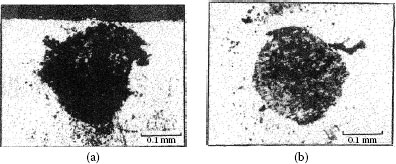
FIGURE 7.27
Contacts that acquire insulating films because of fretting: (a) tin–lead plate (the black oxide covered surface and debris should be noted) (150 gf; 20 μm wipe; 104 cycles); (b) palladium contact covered with and surrounded by frictional polymers (50 gf; 20 μm wipe; 8 Hz, 105 cycles).
The objective of Section 7.3 is to consider mechanisms of fretting degradations, to survey contact material behavior and the effect of operational parameters on contact resistance, and to provide design guidelines for fretting control in electronic connectors. The role of contact lubricants in preventing fretting problems and in recovering failed connections in favorable cases is considered in Section 7.4.
Fretting motion in a contact interface occurs when a force applied in a direction parallel to the interface exceeds the friction between the mating surfaces. Coefficients of friction typically are the same as those observed for metals under adhesive sliding conditions, about 0. 15–1.0 or lower [113]. A high normal force can minimize the possibility of motion. Contact springs can be designed to be very flexible and minimize fretting displacements [114].
Assuming that an interfacial displacement of amplitude δ occurs, the resulting contact surface damage will depend on the magnitude of δ. This has been categorized by various authors [115,116,117] into four regimes (the first three for fretting and the fourth for gross movement):
i. If δ is small and directly proportional to the tangential force (T) and there are no indications of microscopic interfacial sliding, the sliding regime is defined as sticking. The linear dependence of T on δ illustrated schematically in Figure 7.28 corresponds to an elastic shear stress–strain curve for the two mating surfaces. This indicates that the macroscopic displacement between the contacting surfaces is mainly accommodated by elastic deformation in the near-surface regions of the two components. The interface is maintained under stick contact conditions by the adhesively joined asperities; larger displacements will cause plastic deformation and shearing in the fretting direction. The stick regime may occur for movements of about 1 μm depending on the material, contact geometry, and other factors. Figure 7.29 illustrates stick for contacts in a crossed cylinder device [115]. Although essentially no detectable surface damage may be generated initially, the sticking regime cannot be dismissed as non-fretting since reciprocating motion may lead to the nucleation and propagation of surface fatigue cracks, particularly along the rim of the contact area, which would lead to wear debris formation.
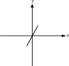
FIGURE 7.28
Plot of tangential force T versus the interfacial displacement δ in the sticking regime. The linear relationship indicates that macroscopic displacement between the contacting surfaces is accommodated by elastic deformation. (After O Vingsbo, S Soderberg, Wear 126: 131–147, 1988 [115].)
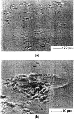
FIGURE 7.29
(a) Fretting wear scar, characteristic of stick contact conditions and (b) detail of the fretting wear scar in (a): material, niobium, 2 μm wipe; 1.09 kgf, 100 Hz; 106 cycles. (After O Vingsbo, S Soderberg, Wear 126: 131–147, 1988 [115].)
ii If δ is smaller than a threshold transition amplitude δt as illustrated in the left-hand side of Figure 7.30, the sliding regime is defined as partial slip [117]. Under this interfacial motion condition, an inner stick zone is surrounded by an annulus where displacement is small but where slip occurs and the force–displacement curve resembles a hysteresis curve centered around the origin. At small partial slip amplitudes, the contact stick zone remains relatively undamaged, but the surrounding annular slip region may host areas of crack formation, fretting fatigue, and wear debris. This is shown in Figure 7.31 for A1S1 304 stainless steel. Movements are of the order of ~1–3 μm. Clearly, there is an inverse relationship between the width of the slip annulus and the dimensions of the inner stick zone, that is, a large stick zone is associated with a narrow slip region.
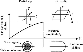
FIGURE 7.30
Sliding regimes for a contact interface consisting of a sphere or the hemispherical surface of an asperity tip in contact with a flat with a normal force. (After S Hannel et al.,Wear 249: 761–770, 2001 [117])
iii If δ is larger than δt, the sliding regime corresponds to gross slip. In this case, sliding occurs across the entire contact area and the force–displacement curve is essentially trapezoidal as illustrated schematically in the right-hand side of Figure 7.30. The tangential force T is independent of the displacement amplitude δ and is related to the normal contact force P in accordance with the conventional relation
where μ is the friction coefficient. Initial gross slip favors the elimination of surface native oxides and promotes strong metal–metal interaction. The friction coefficient increases until the partial slip condition is reached, that is, gross slip. All asperity contacts are broken during each cycle. Asperities slide across several others of the opposing surface. Damage is extreme with possible delamination wear. Movements of 10–100 μm are typically involved. Figure 7.32 for AISI 1018 steel illustrates this regime [115].
iv Clearly, there will be an intermediate sliding region where displacement occurs via both partial slip and gross slip. This sliding regime is appropriately defined as mixed slip. Fretting associated with the mixed slip regime is generally characterized by an initial gross slip condition followed by a partial slip situation. Initial gross slip favors the elimination of surface native oxides and promotes the formation of metal–metal metallurgical bonds. The friction coefficient increases until the partial slip condition is reached. For intermediate displacement amplitudes and with increasing number of fretting cycles, the variation of tangential force with reciprocating displacement evolves from that typical of gross slip to one characteristic of partial slip. This evolution of the tangential force–displacement curve with increasing number of fretting cycles is illustrated in Figure 7.33b. In contrast, the corresponding curves for partial slip and gross slip remain stationary as represented schematically in Figure 7.33a and c.
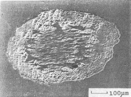
FIGURE 7.31
Fretting wear scar characteristic of mixed stick and slip contact conditions: material, AISI 304; 4 μm wipe; 1.15kgf, 100Hz; 106 cycles. (After O Vingsbo, S Soderberg, Wear 126: 131–147, 1988 [115].)
v. Reciprocating sliding. With large displacements, say more than 100–200 μm, there is sliding wear with mechanisms and rates that have been described in Section 7.2.
Degradation mechanisms of materials for relatively long traversals of contact insertion and withdrawal in a connector are not fundamentally different from those in the gross slip regime. Although wear debris, corrosion products, and frictional polymers tend to accumulate more readily on surfaces with the smaller fretting movements, wear rates and the utility of lubricants in mitigating failures are similar for fretting and for gross sliding. Thus, many investigators have conducted studies with large movements (e.g., 0.3 mm in [75], 0.4 mm in [118], and 10 mm in [119]) and obtained results that are directly applicable to the micro-movements of fretting. The so-called fretting maps describe the relationship between tangential force and displacement [115,117] for categories (i)–(iv) listed above.
7.3.3 Static versus Dynamic Contact Resistance
Fretting leads to the formation of metallic wear and oxidized debris by adhesion, abrasion, and delamination processes. When the contact metal is non-noble or catalytically active (examples are discussed later), insulating materials appear in the contact interface. If these substances are inorganic solids, like oxides, the process is called “fretting corrosion.” Catalytic materials such as the platinum group metals yield organic contaminations, or “frictional polymers.” The accumulation of insulating solids in the contact zone causes the electrical resistance to increase. Figure 7.34 is a representation of this process.
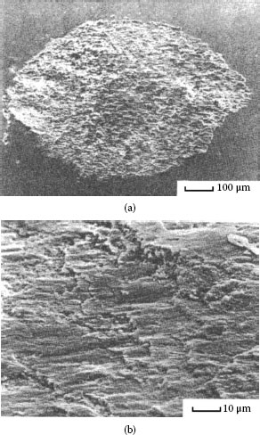
FIGURE 7.32
(a) Fretting wear scar, characteristic of gross slip contact conditions and (b) detail of scale-like topography of wear scar: material, AISI 1018; 15 μm wipe; 570 gf; 20 kHz; 106 cycles. (After O Vingsbo, S Soderberg, Wear 126: 131–147, 1988 [115].)
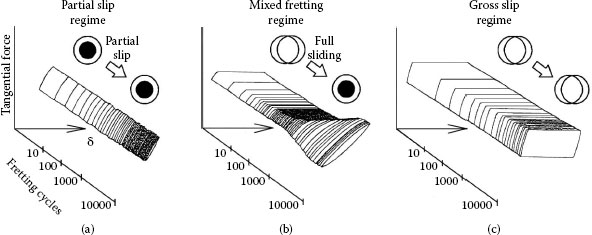
FIGURE 7.33
Schematic representation of the three slip regimes in interfacial sliding. (From S Hannel et al. Wear 249: 761 – 770, 2001, Figure 7.3 [117]. With permission)
There are two aspects of electrical resistance degradation: (1) the “static” contact resistance of the system at rest, and (2) the variability of contact resistance that may reach high values during fretting, even open circuit, for nanoseconds up to much longer times depending on the velocity of the reciprocating displacements, cycle rate, contact materials, and the physical properties and thickness of the insulating layer. The practical consequences of fluctuating contact resistance in digital circuitry may be errors in signed transmission. An elevation of static contact resistance in power circuits can lead to electrical failure of the connection by Joule heating.
There has been considerable speculation about the mechanisms responsible for contact resistance changes in fretting corrosion, and several [120,121,122,123] models have emerged. Two of these models are summarized below. The first model is the so–called asperity model. This model proposes that the area of metal–metal contact decreases continually during reciprocating motion as metallic asperities and wear debris are transformed into oxides, whether layered and adherent or loose and particulate. There is also a volume growth, from metal to oxide, which further tends to separate the contact surfaces. The reduction of contact area causes contact resistance to increase, and motion eventually leads to momentary loss of asperity contact followed by the re-establishment of contact with another array of asperities. However, an analysis [124] of the relation between the duration of contact resistance excursions and fretting velocity for copper contacts in a particular application showed that excursions are generally too brief to be explained by the asperity model. The second model proposed to account for contact resistance changes in fretting corrosion is the granular interface model. In this concept [123], fretting debris is composed of metal particles, oxide-covered debris, and fully oxidized material. The contact interface is represented schematically in Figure 7.34c. The resistance of such a debris-filled interface would be very high, but small displacements may alter the resistance if an electrical conduction path is developed via contacting metal debris particles. Changes in contact resistance due to interfacial displacements would be momentary.
It is likely that both the asperity and granular interface models have elements of validity for actual electrical contacts, and even coexist with a relative importance that depends on the material system involved. It has been shown [118] that with the increase in static contact resistance from fretting, the frequency of short-term resistance excursions increases as well.
7.3.4 Field and Laboratory Testing Methodologies
In fretting test methodologies, the extent of fretting depends on the method used to induce movement and on the apparatus employed. Ensuing contact resistance changes may depend on the electrical current level and on the procedure for measuring contact resistance. This was not always recognized, and an early example of variable results involved a laboratory determination of contact resistance changes of palladium contacts due to fretting [108,125,126].
7.3.4.1 Generation of Fretting Displacement
All separable connectors can be made to fret, provided that the stresses are applied which exceed their contact withdrawal (retention) force [100]. Realistic hardware evaluation depends, however, on imposing only as much external force as is involved in the application [102]. The origin of the force may be thermal, mechanical, or electromagnetic, as described above. Nevertheless, hardware studies are sometimes conducted by forcing displacements, as when a printed circuit board inserted in a connector is rocked [111,127]. Laboratory hardware testing has also been conducted by using severe external vibrations [100,105], by thermal cycling [111], and by imposing a reversing force of constant magnitude to the samples [128]. Materials studies are usually made using equipment that utilizes idealized contact geometries and where fretting is caused by either thermal changes [101,129,130,131,132,133] or mechanical means [101,102,104,110,125,129,133,134,135,136,137,138,139,140,141], or is electro-magnetically induced [102,117,139].
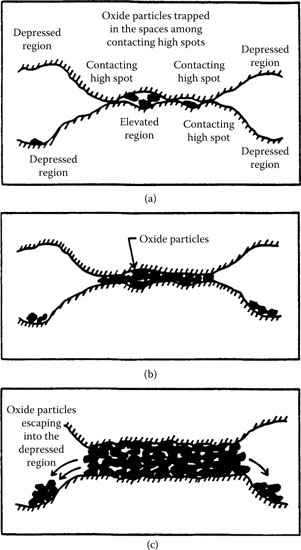
FIGURE 7.34
Schematic representation of formation and accumulation of fretting corrosion solids: (a) accumulation of oxide particles in the spaces among the high spots; (b) integration of a company of high spots into one single united area, after the space among the high spots is filled by oxides; (c) spilling of oxide particles into the adjoining depressed regions. (After IM Feng, BG Rightmire, Lubrication Engrg 9: 134–136, 1953 [120].)
7.3.4.2 Determination of Contact Resistance
In laboratory testing, contact resistance may be measured by dc or ac methods at low voltage and current in order to preclude heating or electrical breakdown of insulating films that may be present [142,143], and with no current flowing except during the periodic resistance measurement. Alternatively, the circuit may be continuously powered during fretting at levels consistent with the intended application. Static contact resistance changes due to fretting were found [118,127] to be much less than the changes observed during transient operation. Another method [128] for evaluating contact resistance variability during fretting obtains the spectral content of the voltage drop using a high-speed recorder when passing a dc current through the contacts.
The testing apparatus used for investigations of fretting corrosion of electrical interfaces is generally designed to generate small reciprocity displacements reproducibly and allow simultaneously for measurements of contact resistance along the wear track. A stationery rider (usually a hemispherically ended rod, rivet, short segment of a cylinder, or connector contact) is usually dead-weight loaded to produce a force ranging from 5 to 500 gf against a flat or other suitable specimen located on a precision slide table. The table is often driven by a dc stepping motor through a micrometer screw. The motor is interfaced to a computer that controls track length and other test parameters. Investigations of the effects of fretting corrosion are generally made in an uncontrolled environment.
The accurate measurement of electrical contact resistance requires the use of a dc four-wire dry circuit technique [143] (see Section 2.7.7) with an open circuit voltage of 10–20 mV and current limited to 100 mA. Current and voltage leads are clamped to the rider and flat. The computer monitors and samples contact resistance at preprogrammed numbers of cycles. A variety of testing devices have been described over the years [117,137,139,140,141,150].
A useful categorization of contact resistance stability in comparing materials in the work carried out by Antler divided fretting behaviors into three classes: stable or acceptable (Type III), unstable (Type I), and intermediate (Type II). These behaviors are defined in Table 7.1 according to both the numbers of cycles required to attain 10 mΩ and the value of the contact resistance after 105 reciprocating cycles. Figure 7.35 illustrates representative behaviors for various materials from a study [144] of frictional polymerization.
TABLE 7.1
Classification of Contact Resistance Behaviors
Type I (Unstable) |
Type II (Intermediate) |
Type III (Stable) |
|
Cycles to attain 10 mΩ |
<5000 |
>5000 |
>105 |
Contact resistance by 105 cycles |
>1 Ω |
<1 Ω |
<10 mΩ |
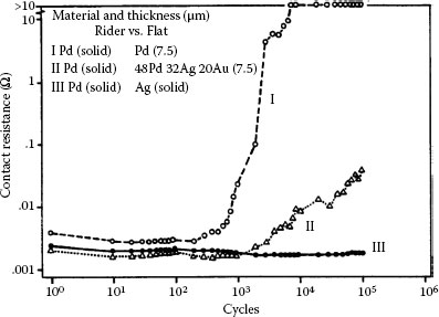
FIGURE 7.35
Contact resistance behaviors (typical) from fretting for 105 cycles at 50 gf and 8 Hz with a 20 μm wipe: curve I, unstable behavior, rise to high value after little fretting; curve II (intermediate), delayed rise and maximum value below 1 Ω; curve III, stable behavior; details of rider-flat combinations are given in the graph, and Table 7.1 defines the contact resistance behaviors. (After M Antler, Wear 81, 159–173, 1982 [144].)
7.3.5.2 Metals Having Little or No Film-Forming Tendency
7.3.5.2.1 Silver versus Silver
The earlier data of Figure 7.25 illustrated the mechanical wear properties of silver–silver contacts and showed that tarnish layers are easily displaceable. Similar effects are observed for large displacements in the fretting regime. Figure 7.36 illustrates the evolution with fretting time of the contact resistance between silver-plated copper surfaces in air, at contact loads of 20 N and 60 N for relatively large fretting displacements of 20 μm and 60 μm (i.e., gross slip regime) at a reciprocation frequency of 100 Hz [95]. The measurements were made for both tarnished and untarnished contacts. For untarnished contacts, Figure 7.36a, contact resistance increased gradually with fretting time. This is as expected since, as explained earlier in relation to adhesive wear, clean silver contacts tend to weld. In fretting motion characterized by relatively large displacements, mechanical damage in fretting was similar to that observed under full sliding conditions (Figure 7.25a), thus increasingly exposing the underlying oxidation-prone copper [95]. The rate of contact resistance increase was found to increase with fretting displacement but was relatively independent of contact load. The observations for tarnished silver were different as illustrated in Figure 7.36b. Initially, contact resistance decreased rapidly due to breakup and displacement of the tarnish layers and subsequent exposure of fresh metallic silver. Exposure of metallic silver led to contact sticking and thus to a sharp drop in contact resistance. Eventually, fretting displacements caused silver removal and subsequent exposure of the underlying copper, from which oxidized particle debris was generated. This eventually led to an increase in contact resistance.
The effects of fretting displacement amplitude on contact resistance in silver–silver contacts under relatively light contact loads (50 gf), compared with such effects in other materials at this contact load, are shown in Figure 7.37. These data show that the stability of silver is superior to that of most other electrical contact metals. Silver thus displays stable (Type III) behavior when mated to itself. This stability stems from the attributes that silver is low wearing, oxide free, and does not form frictional polymers [104]. Because silver is prone to tarnish in atmospheres containing certain sulfur or chlorine compounds, it finds only limited application in electronic connectors. It is used successfully as a finish on aluminum busbar contacts [103] and is widely used as a finish on copper. As described in Chapter 8, the thickness of silver coatings on copper must generally be larger than about 5 μm in electronic connectors and 15 μm in high power connectors in order to mitigate the deleterious effects tarnish (e.g., silver sulfide) growth in a contaminated environment.
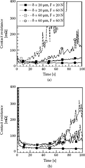
FIGURE 7.36
Typical trends of contact resistance during fretting (100 Hz) between copper surfaces plated with 4-μm-thick silver layers. Fretting was conducted at a contact load of 20 N or 60 N and with a displacement of 20 μm or 60 μm: (a) untarnished silver and (b) tarnished silver. (After A Kassman Rudolphi, S Jacobson, Tribology Inter. 30: 165–175, 1997 [95].)
Although solid gold has been found to form a trace of polymer when fretted in benzene vapor [104] or immersed in an oil [99], this contaminant has no detectable effect on connector contact resistance due to its small amount. Polymers have also been detected on gold surfaces in continuous sliding at 5–15 gf, as in instrument slip rings [119,145,146]. Gold surfaces when scratched have been found to catalyze the decomposition of adsorbed organic compounds [147]. Figure 7.37 presents data for the fretting of solid gold against a 99.0% pure hard gold plate. Fretting displacements in contacts consisting of gold sliding over gold lead to stable (Type III) behavior [99].
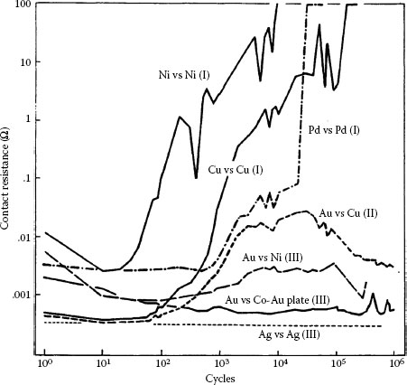
FIGURE 7.37
Contact resistance behaviors for various combinations of materials fretted at 50 gf with a 20 μm wipe at 4–8 Hz (contact resistance behaviors according to Table 7.1). Type I (Unstable): solid nickel versus nickel plate 2.5 μm thick on copper; solid copper vs. solid copper; solid palladium versus clad palladium 5 μm thick on nickel. Type II (Intermediate): solid gold vs. solid copper. Type III (Stable): solid gold vs. nickel plate 2.5 μm thick on copper; solid gold vs. 0.2% cobalt–gold plate 0.6 μm thick on nickel underplate and 2.5 μm thick on copper; solid silver vs. solid silver. (After M Antler, MH Drozdowicz, Wear 74: 27–50, 1981–82 [99].)
7.3.5.3 Non-Noble Metals/Fretting Corrosion
7.3.5.3.1 Nickel versus Nickel and Copper versus Copper
Non-noble metals form fretting corrosion products that may have a significant effect on contact resistance after few cycles of operation. This is illustrated in Figure 7.37 for nickel and copper contacts mated to themselves [99]. Mechanical disruption of superficial initial oxides, if present, occurs within 10 cycles with falling contact resistance, and then contact resistance rises rapidly, attaining levels of 1–10 Ω in only 103 cycles.
7.3.5.3.2 Tin-Base versus Tin-Base Surfaces and Electrodeposited Thick Sn60–Pb40 Solder versus Solder
Contact resistance problems due to fretting between surfaces coated with tin or a tin-base coating are often encountered. Tin-base coatings and solder are used in low-cost connectors for consumer applications [101] on the contacts of pluggable integrated circuits and their sockets [105,109,148] and in some computer products [149]. Examples of contact resistance traces during fretting motion in tin-plated copper contacts at room temperature and at a relative humidity (RH) of 55% are illustrated in Figure 7.38, where the tin layer thickness was 3 μm [150]. In the two contact resistance traces, the initial large resistance stemmed from the presence of a thin film of insulating tin oxide on the surface of the tin-plated copper alloy contact, which was removed after the first few reciprocating displacements. Following the initially large resistance decline, the gradual increase in contact resistance was attributed to the slow buildup of tin oxide between the contact surfaces. The subsequent rapid increase in contact resistance was due to the large accumulation of wear debris as illustrated schematically in Figure 7.34, consisting of tin metal and oxidized tin. The buildup of oxidized tin reduces the electrical conducting area.
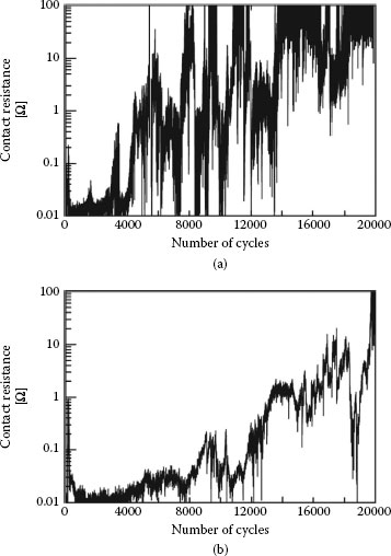
FIGURE 7.38
Change in contact resistance of tin-plated copper contacts as a function of fretting cycles obtained at different frequencies (a) 3 Hz and (b) 20 Hz. (tin layer thickness: 3 μm, amplitude: 25 μm, temperature: 22°C, humidity: 55% RH, normal load: 0.5 N (~50 gf), current: 0.1 A). (After YW Park et al., Tribology International 41: 616–628, 2008 [150].)
The data of Figure 7.38a and b were recorded at a frequency of reciprocating motion of 3 and 20 Hz, respectively, but the wear path length was maintained at 25 μm. In these examples, the contact was deemed to have failed when the contact resistance reached a value of 100 mΩ. A comparison between Figure 7.38a and b reveals that failure was reached after about 20,000 cycles at 20 Hz, but only after about 7,000 cycles at a frequency of 3 Hz. Thus, the effect of increasing the frequency of reciprocating motion over a wear track of fixed length was to decrease the degradation rate of contact resistance per fretting cycle. However, there is another way of interpreting the fretting corrosion data. At 20 Hz, the total time of wear generation and oxidation of the tin surfaces was about 20,000/20 = 1,000 s, whereas this time interval increased to about 2,300 s at 3 Hz. Thus, the rate per unit time of contact degradation due to fretting corrosion actually decreased at the smaller displacement frequency since failure occurred after a longer time. This decrease may stem from effective dispersal of oxidized debris from the contact at lower frequencies.
The time to failure of the tin-plated contacts as a function of fretting motion frequency and displacement amplitude associated with the data of Figure 7.38 is summarized in Figure 7.39. The data show the clear decrease in rate per unit time of fretting corrosion (an increase in time to failure) with decreasing displacement frequency, as explained above. In addition, an increase in displacement amplitude also leads to a decrease in the fretting corrosion rate. These observations are attributed to the more rapid dispersal rate of wear debris from a longer track at a selected frequency, and hence to the smaller rate of debris accumulation in the contact interface in this case. Clearly, small fretting displacements cannot be effective in dispersing debris out of the wear track. Small displacements thus lead to quicker accumulation of insulating material in the contact interface, and hence to quicker contact degradation. The dependence of fretting corrosion on wipe distance, wipe frequency, and other parameters will be addressed in greater detail in Section 7.3.7
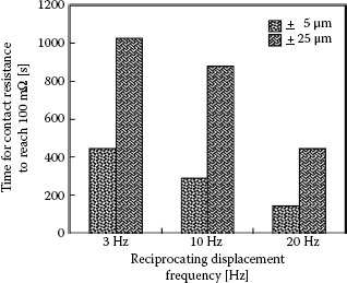
FIGURE 7.39
Time required for the contact resistance to reach a threshold value of 100 mΩ for track lengths of 5 μm and 25 μm at fretting frequencies of 3, 10, and 20 Hz (temperature: 22°C, humidity: 55% RH, normal load: 0.5 N (~ 50 gf), current: 0.1 A). (After YW Park et al., Tribology International 41: 616 – 628, 2008 [150].)
The surface morphology of the tin-plated contact regions associated with the data of Figures 7.38 and 7.39 is shown in Figure 7.40 [151]. Wear debris is ejected laterally outside of the fretted zone. Although the shape of the fretted zone was not affected significantly by the fretting conditions, the dimensions of the damaged contact zone increased in accordance with an increase in track length. The debris particles were found to consist of a mixture of tin metal, tin oxide, copper, and copper oxide, with the copper originating from the plated substrate. Electrical contacts coated with tin–lead are characterized by poor contact resistance performance in fretting (Type I, Unstable) and the performance of tin–lead versus gold is even worse (Figure 7.41). Reasons for this behavior are discussed later in Chapter 8. The optical micrograph of Figure 7.27a shows the black spot typically produced by fretting corrosion.
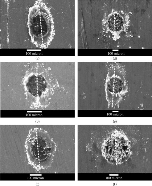
FIGURE 7.40
Surface morphology of the worn areas on the tin-plated contacts associated with the data in Figures 7.38 and 7.39, after 20,000 fretting cycles. The micrographs show the fretted region for the following test conditions: (a) amplitude: 5 μm and 3 Hz; (b) amplitude: 5 μm and 10 Hz; (c) amplitude: 5 μm and 20 Hz; (d) amplitude: 25 μm and 3 Hz; (e) amplitude; 25 μm and 10 Hz; and (f) amplitude: 25 μm and 20 Hz. The dotted line identifies the fretting direction. (After YW Park et al., Surface and Coatings Technology 201: 2181 - 2192, 2006 [151].)
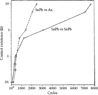
FIGURE 7.41
Contact resistance vs. number of fretting cycles for tin–lead vs. tin–lead compared with gold vs. tin–lead-plated contacts (50 gf; 8 Hz, 10 μm wipe). (After M Antler, IEEE Trans Comp, Hybrids, Manuf Technol 7:129–138, 1984 [180].)
7.3.5.3.3 Other Base Metals Mated to Themselves
Many base metals such as aluminum [130,142,152] and various copper alloys [131,133,153,154] have been found to have unstable contact resistance due to fretting. Although the failure trends illustrated for tin-plated copper in Figures 7.38 and 7.39 are typical of the effects of fretting corrosion for many materials, the trends do not necessarily apply to all contact materials or to all fretting conditions. For example, Figure 7.42a illustrates the effects of fretting corrosion for monometallic contact interfaces comprising bare copper, brass, nickel, and aluminum where reciprocating motion was imposed at 16 Hz, at a contact load of 0.3 N with a fretting amplitude of 30 μm [153]. In all cases, contact resistance first decreased and then increased with increasing fretting time. In the case of copper, the variations in contact resistance with increasing fretting time were undulatory. These undulations affected the fretting time necessary to reach a selected high contact resistance. This is illustrated in Figure 7.42b where we note that the time interval to generate a contact resistance of 100 mΩ in the copper contacts associated with the data of Figure 7.42a first decreased, that is, the fretting corrosion rate increased, and then the time to 100 mΩ decreased. This decrease occurred as the fretting amplitude was extended beyond 40 or 60 μm, depending on the fretting frequency.
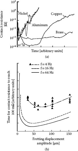
FIGURE 7.42
(a) Effect of fretting time on contact resistance in monometallic contacts of bare copper, brass, nickel, and aluminum, at a fretting frequency of 16 Hz, a contact load of 0.3 N and a displacement amplitude of 30 μm and (b) dependence on displacement amplitude of the time required for contact resistance to reach a value of 100 mΩ in copper–copper contacts. (After PH Castell et al., Proceedings of the 12th International Conference on Electric Contact Phenomena, Chicago, pp 75–82, 1984 [153].)
The data of Figures 7.38, 7.39, and 7.42 illustrate the observations that the effects of fretting corrosion on contact resistance are generally strongly influenced by the frequency and the amplitude of the reciprocating motion. Similar data associated with copper–copper and gold-plated copper contacts sliding in reciprocating motion will be described later. These observations are particularly relevant to the performance of electronic connectors in the transportation industry where fretting is an established connector degradation mechanism [155]. However, the data of Figure 7.38, Figure 7.39, Figure 7.40, Figure 7.41 and Figure 7.42 also illustrate frequent observations that different non-noble contact materials do not necessarily behave in the same way in fretting interfaces. Conflicting trends regarding the effects of fretting can only stem from differences in the mechanisms responsible for the generation of metal and oxidized metal detritus for different materials in sliding. On this premise, the effects of fretting corrosion on contact resistance may be expected to depend not only on chemical properties of the surfaces in contact, such as susceptibility to oxidation, but also on the physical properties such as metallurgical structure, surface hardness, and so on of the mating materials.
7.3.5.4 Frictional Polymer-Forming Metals
Polymer-forming materials include [104] the four platinum group metals having technological importance in contacts, platinum, palladium, rhodium, and ruthenium, and many of their alloys. In addition, several other metals yield polymers when fretted in benzene vapor including tantalum, molybdenum, and chromium [104].
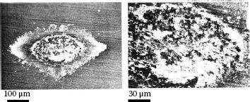
FIGURE 7.43
Wear track on the palladium flat after fretting for 105 cycles against a solid palladium rider. The debris consists of mixture of palladium wear particles and frictional polymer. The micrograph at the right provides a magnified view of the wear track shown on the left. (After M Antler, Wear 81, 159–173, 1982 [144].)
7.3.5.4.1 Palladium versus Palladium
The contact resistance behavior of palladium on palladium in reciprocating motion is unstable (Type I), as shown in Figure 7.37 [99]. Figure 7.43 shows the wear region on the flat palladium surface at the end of the test corresponding to Curve I in Figure 7.35 [144]. The visible loose debris contained only palladium and residues of polymeric material, that is, frictional polymer. The formation of the frictional polymer during fretting was responsible for the rise in contact resistance. The surface was worn only slightly, which indicates that frictional polymers are electrically insulating but provide both lubricating function and wear inhibition. The performance of platinum, rhodium, and ruthenium on themselves under the same test conditions would undoubtedly be Type I.
7.3.5.4.2 Palladium Alloys Mated to Themselves
Clad [156] and electroplated [157] palladium–silver alloys and clad palladium–gold?silver alloys [158] are potential replacements for gold connector contacts. These materials are also less reactive than pure palladium to chlorine-containing [159] and other [160] compounds in the atmosphere. DG R-156, an inlay with a wt% composition of Pd60Ag40 having a gold-rich surface with a diffusion gradient in the body of the alloy, is also used in connectors [161]. The low polymer-forming tendency of materials from this group, especially DG R-156 and the palladium–silver alloys from Pd70Ag30 to Pd30Ag70, compared with that of palladium, is significant [136,144]. Electroplated palladium–nickel alloys containing 70–85 wt% palladium are also widely used, but perform poorly in fretting [136,144,157,162,163,164,165,166,167]. Flash gold over-platings can improve the performance of these metals until the gold is lost by wear.
Promising substitute materials for hard gold as a contact finish also include palladium–cobalt with cobalt concentrations ranging from about 10 to 20 wt%, and palladium-nickel [167,168,169]. Figure 7.44 is adapted from investigations of these materials [169] and illustrates the evolution of the friction coefficient and contact resistance of sliding contacts with gold-flashed (GF) palladium–nickel, palladium–cobalt, and nickel–gold, all on a nickel underplate and a gold flash. The data suggest superior wear properties for GF palladium–cobalt.
7.3.5.4.3 Mechanisms of Frictional Polymerization
The mechanisms of frictional polymerization are not well understood. Despite considerable speculation [147,170,171,172,173], the hypothesis advanced by Hermance and Egan [104] is plausible since it is consistent with most observations of the composition and physical properties of the polymeric materials [119,146]. This hypothesis states that polymer precursors are strongly adsorbed on the sliding surfaces of the catalytic metals and react among themselves to form high-molecular-weight, cross-linked solids. This simple model of polymerization [172,173,174] of adsorbed organic species is consistent with observations of the locations where polymeric material accumulates at the periphery of a contact undergoing reciprocating sliding motion. “Wiping” may also activate the surface to cause polymerization.
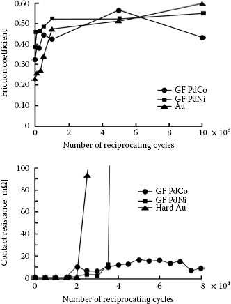
FIGURE 7.44
Evolution of the friction coefficient and contact resistance of sliding contacts with gold-flashed (GF) palladium-nickel, palladium–cobalt, and nickel gold, all on a nickel underplate and a gold flash. The data suggest superior wear properties for GF palladium–cobalt. (After G Holmbom et al., Proc. 31st Annual IICIT Connector and Interconnection Symposium, Danvers, MA, pp. 313–320, 1998 [168].
Poisons for conventional catalysis reactions are ineffective in stopping frictional polymerization, although the rate of reaction can be reduced when non-polymerizable low-molecular weight compounds are present that compete for surface sites with polymer precursors. The alloying of catalytic metals with non-catalytic elements reduces the population density of active catalytic sites and thus reduces susceptibility to frictional polymer formation. The particularly low susceptibility of Pd60Ag40 to frictional polymer formation [174] suggests a special role of silver in mitigating polymer growth.
Although most laboratory work has been conducted with artificial atmospheres containing high levels of pollutants, any open-air environment contains enough organic material for frictional polymers to form in sufficient quantity to cause electrical contact problems at some juncture in separable palladium–palladium contacts.
More recently [175,176], studies of relays indicate that palladium oxides, or related palladium compounds, can be formed on palladium–palladium contact surfaces operating in air in inactive (zero discharge) circuits when the level of organic pollutants is very low. Relay contacts experience both impact and slight wipe, but it appears that the wipe action is largely responsible for the oxidized palladium debris. The accumulated debris leads to a significant increase in contact resistance. The presence of organics and water vapor suppresses the reaction [177]. Oxidation has been hypothesized to occur because of the mechanical energy involved in contact closure, hence the term “mechanochemical reaction” for the phenomenon.
The passage of current stabilizes contact resistance because of Joule heating, which decomposes the palladium oxides to palladium metal. Although these studies were not directed to electronic connectors, they are relevant to them. The chemistry of this oxidation and of organic polymer formations is complex. Further studies are required to provide a full mechanistic explanation for the activity of palladium during fretting.
From an engineering point of view, the use of palladium and palladium alloys as contact materials for electronic connectors is not without risk. This is shown by palladium–nickel alloy electrodeposits that also form both oxides and frictional polymers of unknown composition [165]. Flash gold overplates on palladium and palladium–nickel are marginally effective in stabilizing contact resistance during fretting (see later). Thorough testing is required before catalytic contact metals can be considered for service.
7.3.5.5 Dissimilar Metals on Mating Contacts
Cold welding and transfer may occur during fretting, particularly when the metals are noble, ductile, or soft, but only where the sliding surfaces are clean and the surface layers are sufficiently thick. This was indicated earlier in relation with silver-plated surfaces (Figures 7.25 and 7.26). Otherwise, gross cold welding or even micro-welding at contact asperities is generally negligible in electrical contacts. Many practical systems involve contacts made of materials having different composition, form, or mechanical characteristics. In these situations, fretting will generally lead to changes in the composition of the contact interface from the composition that existed initially, and thus affect the ensuing contact behavior. Several important systems have been studied with contact finishes of sufficient thickness to preclude wear-out during testing. Important such systems are discussed below.
7.3.5.5.1 Palladium versus Gold or Gold Alloys
Gold and gold–silver surfaces sliding on palladium were found to be satisfactory [178,179] in early investigations of electrical contact applications, in contrast to all-palladium interfaces that produce frictional polymers. This is because pure gold [137], high-karat gold alloys [137], and gold–silver alloys [144] are softer than most forms of palladium. Consequently, transfer takes place primarily to the palladium surface, so that the system becomes an all-gold or all-gold alloy. Type III (Stable) contact behavior then occurs, identical to that in Figure 7.35 for the palladium versus silver couple.
Table 7.2 lists various materials that were mated to palladium in an extensive study [144] of fretting. Type III alloys include thick gold electrodeposits containing about 0.2 wt% cobalt, Au99Co1, Au98Ni2, Au70Ag30, Au69Ag25Pt6, and several silver–palladium and silver–palladium–tin alloys.
Figure 7.45 illustrates one of these systems, solid palladium versus gold, where the palladium surface became covered by transferred gold. There was little debris and no polymer. On the other hand, if a metal that is significantly harder is mated to palladium, transfer will be from the palladium surface, thereby making the system all-palladium with resultant Type I (Unstable) contact resistance behavior. An example of this type of material combination is Au75Cu25 (KHN25 = 24.3 × 10² N mm−2) mated to palladium (KHN25 = 19.2 × 10² N mm−2). Figure 7.46 shows the Au75Cu25 surface to which solid palladium has transferred and produced frictional polymers. Other examples from Table 7.2 of hard metals to which solid palladium transfers include Au55Ag39Cd3In3 and Pd60Ag40.
TABLE 7.2
Materials Mated to Solid Palladium (50 gf, 20 μm Wipe, 8 Hz, 105 Cycles)
Thickness (μm) and Behavior Type |
||||
Metal |
Forma |
I (Unstable) |
II (Intermediate) |
III (Stable) |
Gold and gold alloys |
||||
Au |
Solid |
>1000 |
||
Au |
Clad |
1.25 |
3.8, 7.5 |
|
Au |
Clad |
0.75/Pd |
||
Au |
Clad |
0.75/Pd60Ag40 |
||
Au |
Electrodeposit,0.2%Co |
0.6b |
3.3 |
|
Au |
Electrodeposit soft/Ru |
0.5/0.5 |
||
Au99 Co1 |
Clad |
2.5 |
||
Au98 Ni2 |
Clad |
2.5 |
||
Au90 Ni10 |
Clad |
1.8 |
||
Au75 Cu25 |
Clad |
2.5 |
||
Au70 Ag30 |
Clad |
1.25, 7.5 |
||
Au69 Ag25 Pt6 |
Clad |
3.8 |
||
Au55 Ag39 Cd3 ln3 |
Clad |
1.2c |
||
Au40 Pd36 Ag24 |
Clad |
1.25 |
7.5 |
|
Palladium and palladium alloys |
||||
Pd |
Solid |
>1000 |
||
Pd |
Clad |
1.25, 3.8, 5.0, 7.5 |
||
Pd |
Electrodeposit |
2.5 |
||
Pd80 Au20 |
Clad |
1.25, 7.5 |
||
Pd80 Ni20 |
Electrodeposit |
2.5 |
||
Pd60 Au40 |
Clad |
1.25, 7.5 |
||
Pd60 Ag40 |
Clad |
1.25, 3.8, 7.5 |
||
Pd50 Ni50 |
Electrodeposit |
2.5 |
||
Pd48 Ag32 Au20 |
Clad |
1.25 |
3.8, 7.5 |
|
Silver and silver alloys |
||||
Ag |
Solid |
1.5 |
>1000 |
|
Ag |
Clad |
1.5 |
7.5 |
|
Ag92 Sn8 |
Clad |
1.5, 7.5 |
||
Ag75 Pd25 |
Clad |
1.5 |
7.5 |
|
Ag75 Pd23 Sn2 |
Clad |
1.5 |
7.5 |
|
Ag75 Pd17 Sn8 |
Clad |
1.5 |
7.5 |
|
Ag60 Pd40 |
Clad |
4.0 |
||
Other metals |
||||
Rh |
Solid |
>1000 |
||
Ru |
Solid |
>1000 |
||
Ru |
Electrodeposit |
1.0 |
||
a Electrodeposits on a Ni underplate, except where indicated by slash (/). Clad meals on Ni interliner, except where indicated by slash (/).
b 15,000 cycles to attain 10 mΩ.
a 20,000 cycles to attain 10 mΩ.
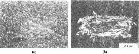
FIGURE 7.45
Specimens from fretting (a) solid palladium rider vs. (b) gold flat (3.8 μm cladding). Gold had transferred to the palladium, making the system all-gold; there was little wear debris. Type III (Stable) contact resistance behavior: 50 gf, 8 Hz, 20 μm wipe, 105 cycles. (After M Antler,Wear 81, 159–173, 1982 [144].)
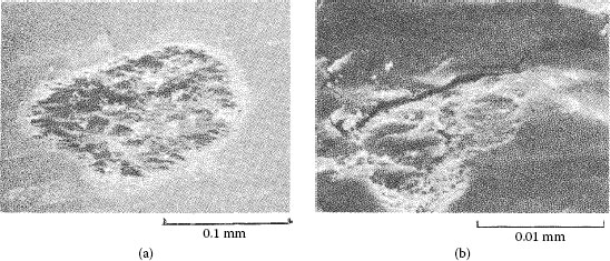
FIGURE 7.46
(a) Au75Cu25 flat (2.5 μm cladding) after fretting against solid palladium rider (palladium had transferred to the flat, making the system all-palladium); debris consisted largely of palladium particles and frictional polymers; Type I (Unstable) contact resistance behavior; (b) as (a), but at a higher magnification (wear of palladium occurs initially by adhesive transfer followed by delamination): 50 gf, 8 Hz, 20 μm wipe, 105 cycles. (After M Antler, Wear 81, 159–173, 1982 [144].)
Metal transfer does not always occur in one direction. If materials are not too unlike in hardness, say, when the hardness differs by about 10% or less, there may be significant metal transport both ways. In these instances, low contact resistance can be maintained if the composition of the rubbing surfaces from initiation of fretting remains predominantly that of non-polymer forming materials.
7.3.5.5.2 Gold versus Nickel and Gold versus Copper
The nickel–nickel and copper–copper systems are characterized by unstable contact resistance behavior (Figure 7.37) because of fretting corrosion [99]. However, the contact resistance behavior improves dramatically when these metals are mated to pure gold [99]. In the case of electrodeposited nickel (KHN25 = 44 × 102 Nmm−2), which is considerably harder than gold, transfer occurs nearly entirely from gold to the nickel with Type III (Stable) behavior, as shown in Figure 7.47. When solid gold is coupled to solid copper (KHN25 = 11.7 × 10² Nmm−2), there is some contact resistance instability (Figure 7.48) with Type II (Intermediate) behavior.
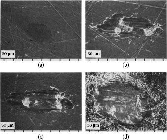
FIGURE 7.47
Scanning electron micrographs of worn flats from runs of increasing duration with solid gold riders on 0.05 μm Co-Au-plated copper flats: (a) 103 cycles; (b) 104 cycles; (c) 105 cycles; (d) 106 cycles. (After M Antler, MH Drozdowicz, Wear 74: 27–50, 1981–82 [99].)
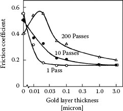
FIGURE 7.48
Variations of friction coefficient measured from cross-rod assemblies between two identical gold-plated palladium surfaces after 1 pass, 10 passes, and 200 passes, as a function of the thickness of pure gold coatings. The palladium consisted of a layer 0.5 μm thick deposited on 1.5 μm of nickel coated on phosphor-bronze rods. (After T Sato et al., Proceedings of the Holm Conference on Electrical Contacts, Chicago, pp 41–47, 1980 [63].)
7.3.5.5.3 Gold versus SnPb Solder
Gold versus electroplated Sn60Pb40 system is characterized by Type I (Unstable) contact resistance behavior [180] (Figure 7.41), because of the transfer of tin–lead to the gold, with resultant fretting corrosion of the base material on both surfaces. Transfer of hard gold does not occur because of the large difference in the bulk hardnesses of the contact metals (electroplated gold containing 0.2% cobalt, KHN725 = 18 × 102 Nmm−2; Sn60Pb40, KHN25 = 1.2 × 10² Nmm−2). Surprisingly, however, contact resistance begins to rise after fewer fretting cycles than in the all-tin–lead contact pair. This result is consistent with hardware experience [105,109,148] and may stem from the formation of hard intermetallic particles or patches in the contact regions due to gold–tin interdiffusion (see Chapter 1). This would affect the mechanics of disruption of surface films on the metals in contact [180,181], as tentatively explained below.
Oxide films fracture when subjected to mechanical deformation. These films thus fracture more easily when grown on a substrate that deforms relatively easily (e.g., a soft substrate) than on a hard surface [182]. During fretting between gold and tin–lead, the harder gold member becomes thinly coated with tin–lead that interdiffuses with the gold, thus forming a thin layer of tin–gold intermetallic compound [the deleterious effects of intermetallic layer growth on contact resistance are addressed in Sections 1.3.3 and 8.4.2]. Because intermetallic compounds are hard, their formation further hardens the gold surface. During fretting, the tin–lead on the two sliding surfaces subsequently oxidizes, but the crack network on the surfaces is less extensive than in the case of tin–lead on tin–lead because the oxide on the tin transferred to the gold cracks less readily. This leads to a more rapid increase in contact resistance than in the tin–lead on tin–lead case, as illustrated in Figure 7.41. This hypothesis is supported by important results of other work on gold-tin contacts [180]. In this work, gold surfaces thinly coated with tin–lead and mated to heavily oxidized tin–lead without wipe were characterized by a significantly higher contact resistance than a contact consisting of a thick tin–lead plating joined to the same oxidized tin–lead specimen. Additional data of the effects of fretting at tin–gold sliding interfaces will be shown later.
The performance of a number of other dissimilar metal contacts has been described, including aluminum versus brass plated with thick silver, cadmium, nickel, tin, or zinc [130], copper versus aluminum plated with silver or tin [102], silver-plated aluminum versus a copper–cadmium alloy plated with tin or silver [103], and several miscellaneous systems [101,104].
Fretting wear may lead to the penetration of a contact material of small thickness, as is often the case with electrodeposited and clad finishes. Contact resistance may change when this occurs, particularly if the substrate is subject to fretting corrosion or frictional polymerization. Examples of variations of contact resistance due to wear-out in sliding interfaces involving different types of coatings and substrate materials are given below.
The following examples illustrate typical observations of wear-out in a gold–copper sliding system. The investigations of interest focused on wear of solid gold riders sliding in reciprocating motion on copper flats and on gold plated copper flats [99]. The results of sliding on bare copper flats have already been shown in Figure 7.37 and indicate that contact resistance increased with increasing reciprocating cycles, reaching the beginning of a maximum plateau after about 2000 cycles and subsequently decreasing after 104–105 cycles from 50–100 mΩ to about 4 mΩ after 106 cycles. In contrast to these observations, the reciprocating sliding of solid gold riders on copper flats plated with a 0.6 μm thick hard gold layer containing 0.2 wt% cobalt, led to a contact resistance that remained low near 1 mΩ until completion of 106 reciprocating cycles [99]. In these two sliding systems, analyses using scanning electron microscopy and energy dispersive X-ray (EDX) spectroscopy [193] revealed that the sliding surfaces consisted of a mixture of gold, copper, and copper oxide.
The contact resistance behavior just described was explained from examinations of sliding surfaces after various numbers of reciprocating cycles involving a solid gold rider sliding on copper plated with only 0.05-μm Co–Au [99]. The thin gold layer was intended to provide good imaging contrast between worn and unworn regions of the copper surface after sliding, in examinations using scanning electron microscopy. Electron micrographs of worn areas on the copper flat, after various number of reciprocating cycles, are shown in Figure 7.47 [99]. With such thin gold layers on the copper, the wear data were essentially identical with those of fretting on unplated copper but the contact resistance did not rise to 50–100 mΩ level. Consistent with the data of Figure 7.37, the worn surface after 103 cycles shown in Figure 7.47a was only lightly burnished, with little gold transfer to the copper and a slight increase in contact resistance probably due to copper oxide formation. Figure 7.47b shows a surface after 104 cycles (contact resistance had increased to 6 mΩ). Adhesive transfer had clearly occurred with the original thin gold coating having been worn significantly from the copper, and the surface scratches of the unworn contact having been obliterated. The rider and the flat had identical appearances. The few loose particles evident on the flat were large and found to contain both copper and gold. Figure 7.47c shows the flat surface after 105 cycles (contact resistance had increased to 3.3 mΩ). The flat was smoother than that shown in Figure 7.47b, which indicates that adhesive transfer between the sliding surfaces had diminished significantly. Figure 7.47d shows a worn copper surface after very long sliding, 106 cycles (contact resistance, 3.0 mΩ). At equilibrium, the worn areas of the two sliding surfaces consisted of a mixture of gold, copper, and copper oxides and copious loose debris had formed. Relative to the concentration of other materials, the gold content on the worn copper surface was found to increase with the thickness of the original gold deposit on the copper. The worn area on copper plated with 0.6 μm of hard gold had an appearance similar to that of Figure 7.47d after 106 cycles, although the resistance had remained small throughout the entire fretting run.
The micrographs of Figure 7.47 show that gold remained in the contact area after 106 cycles, thus contributing to maintaining a low contact resistance (3 mΩ). The data of Figure 7.37 corresponding to solid gold sliding over copper also correspond to a system where the gold supply was copious and, thus, capable of maintaining a low contact resistance for considerably longer than 106 cycles.
7.3.6.2 Palladium-Based Systems
As will be described in detail in Section 7.4.2, thin gold layers or small gold particle dispersions can be effective lubricants. The lubrication of palladium layers by pure gold as measured by Sato et al. [63] is reproduced in Figure 7.48. These data were obtained at a contact load of 300 gf from crossed phosphor-bronze cylinders electroplated successively with a 1. 5μm-thick nickel underplate, palladium to a thickness of 0.5 μm, and gold to the thickness shown in the graph. The data showed that lubrication effectiveness is optimal for a gold thickness of ~0.03–0.2 μm if the number of passes is relatively small. This is consistent with other data for the lubrication by gold on palladium and palladium alloys [63,183,184,185] which, by themselves, are characterized by low resistance to adhesive wear. These observations have stimulated the use of palladium-based finishes that are less expensive than the equivalent thickness of plated hard golds.
If the usual connector durability requirement of up to 200 insertions was the only requirement for resistance to fretting, then flash thicknesses of gold of about 0.2 μm would be adequate for lubrication on palladium. Under practical situations, the number of fretting cycles is generally much greater than 200. As illustrated in Figure 7.48, it is generally found that palladium mated to palladium plated with pure gold (0.05 μm thick) is characterized by Type I (Unstable) contact resistance behavior in fretting at a load as small as 50 gf with a 20-μm wipe. The thin gold layer is readily penetrated for a number of fretting cycles exceeding 200, as suggested by the data of Figure 7.48. Figure 7.49a illustrates the relationship of contact resistance to thickness of electroplated pure gold on a palladium contact mated to solid palladium [186,195]. Even gold layers that were as thick as 0.25 μm altered the contact resistance behavior little from that of palladium versus palladium. Hard golds on palladium (Figure 7.49b) and palladium alloy platings are slightly more durable during fretting than pure gold. The data of Figure 7.49 show clearly the devastating effects on contact resistance of wear-out of the gold layer. In using gold as a protective/lubricant layer on palladium, it is thus important to be aware of durability limit of gold electodeposits.
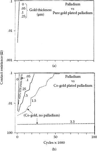
FIGURE 7.49
Contact resistance vs. number of cycles for solid palladium mated to palladium plate 1.5 μm thick on 1.25 μm of nickel underplate on a hard copper alloy substrate: (a) palladium plate, uncoated or coated with pure gold electrodeposit that is 0.05–0.25 μm thick; (b) palladium plate, uncoated or coated with 0.2 wt% cobalt–gold electrodeposit that is 0.05–0.5 μm thick (results from fretting solid palladium against electrodeposited cobalt–gold 1.5 and 3.3 μm thick on a nickel underplate are included for comparison) (50 gf; 8 Hz, 20 μm wipe). (After M Antler, IEEE Trans. Components, Hybrids, and Manufacturing Technology CHMT-8: 87–104, 1985 [195].)
7.3.6.3 Tin and Tin–Lead Alloy Systems
Because of the importance of tin as a contact material, particularly in the automotive industry, fretting in tin-plated contacts has been a topic of intense investigation over many years [80,106,118,127,137,150,151,154,155,184,187,188,189,190,191,192]. The surface morphology of tin-plated copper contacts after fretting has already been illustrated in Figure 7.40 [151]. The probable stages of fretting wear were as follows [150,151]: (i) cracking and partial removal of tin oxide to allow metal-to-metal contact and an initially low contact resistance, (ii) generation of tin oxide debris particles in the contact zone as illustrated in Figure 7.34 simultaneously with slow re-oxidation of the underlying tin, leading to an increase in contact resistance, (iii) steady removal of tin by a combination of adhesive wear and abrasion wear by hard oxide debris articles simultaneously with re-oxidation of tin, thus leading to a further increase in contact resistance, (iv) complete removal of the tin by adhesive and abrasive wear, thus leading to the presence of large amount of oxide debris and an ensuing large contact resistance increase, and (v) exposure of the underlying copper with ensuing fretting corrosion of the copper and the generation of copper oxide debris leading to catastrophic contact failure.
Investigations of fretting in sliding contacts involving tin–lead alloys have been made but have been limited in scope. A limited scanning electron microscope-EDX analysis [193,194] was made of contact surfaces for a system involving plated Sn60Pb40 contacts mated to themselves or to hard gold on nickel underplate. The substrates were brass. During extended fretting runs, contact resistance rose, then fell sharply, and finally increased again. Changing compositions of the surfaces due to wear may have been responsible for these results. An interesting finding was limited transfer of gold to the original tin–lead opposing contact. This was attributed to the much harder copper–tin intermetallics [78] that formed spontaneously on that member on aging, and that became a contact surface after the tin–lead had worn through.
7.3.6.4 Role of Underplate and Substrate
The beneficial effects of an underplate, particularly a nickel underplate, in increasing resistance to wear have been described in Section 7.2.7 (Figure 7.15, Figure 7.16, Figure 7.17 and 7.18). The durability of a thin plated layer in sliding contact over a long track is determined in large part by the composite hardness of the system, as indicated in Equation 7.1. For example, the incorporation of a nickel plate characterized by a bulk hardness of about 44.1 × 10² N mm−2, between a gold deposit and a substrate that is considerably softer such as copper (about 11.8 × 10²N mm−2) is advantageous as was illustrated in Figure 7.15 [59]. The same consideration applies to fretting wear, and Figure 7.50 is an example [99] of the improvement in contact resistance for Au70Ag30 versus 0.05 μm cobalt–gold-plated copper with and without nickel underplate. When an underplate is not used, wear-out of the gold occurs quickly and fretting corrosion ensues (Type I, Unstable contact resistance behavior). With a nickel underplate, contact resistance remains stable for about 100 times more fretting cycles (Type III, Stable contact resistance behavior). It has been shown [99] that Au70Ag30 does not transfer to nickel as readily as does solid gold, and so following wear-out of the 0.05-μm cobalt–gold layer beyond 105 cycles, fretting corrosion of nickel was probably responsible for the insulating materials at the interface which caused the contact resistance to rise. The improvement due to nickel underplate has also been found [99] for larger thicknesses of cobalt–gold-plated layers than those cited here.
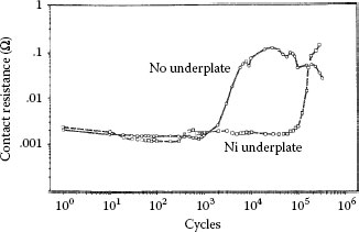
FIGURE 7.50
Contact resistance vs. the number of fretting cycles for solid Au70Ag30 alloy against cobalt–gold-plated copper 0.05 μm thick with and without nickel underplate (2.5 μm). The contact resistance behavior is Type I (Unstable) when cobalt–gold-plated copper is used and Type III (Stable) with the sample having a nickel underplate (50 gf, 8 Hz; 20 μm wipe). (After M Antler, MH Drozdowicz, Wear 74: 27–50, 1981–82 [99].
The rate of electrical contact degradation due to fretting corrosion is influenced by the magnitude of contact parameters such as the amplitude and frequency of fretting displacements, the contact force, the magnitude of electrical current through the contact, environmental factors such as humidity, and other factors. The effects on contact resistance of the amplitude and frequency of the fretting motion in tin–tin contacts have already been illustrated in Figure 7.38, Figure 7.39 and Figure 7.40. Similar effects on other contact materials, and the influence of other contact parameters in sliding interfaces involving a variety of materials, are reviewed in this section.
Contact resistance changes due to fretting corrosion and frictional polymerization can be expected to be influenced by displacement frequency because both contact degradation mechanisms involve rate-dependent surface chemical reactions. Figure 7.51 shows variations in contact resistance for copper versus copper and for gold versus gold-flashed copper systems in fretting through a range of frequencies. The test conditions used in this work [99] consisted of 50 gf (~0.5 N) load, 20 μm wipe, and a cycle rate ranging from 0.04 to 2 Hz. The contact resistance trends in Figure 7.51 are similar to those noted in the case of tin–tin contacts in Figure 7.38, Figure 7.39 and Figure 7.40 where the rate of increase in contact resistance (per unit time) was found to be smaller at the smaller cycling frequencies, and thus the total time interval to reach a selected value of resistance (say to failure) actually increased at smaller frequencies. In the copper–copper contacts in Figure 7.51, it may be verified that the time required to reach a selected contact resistance increased with a decrease in cycling frequency.
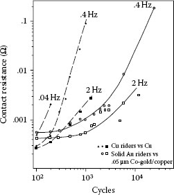
FIGURE 7.51
Effect of the cycle rate on contact resistance: ▲, ●, ◼, copper vs. copper; O, □, solid gold vs. 0.05 μm cobalt–gold on copper; 50 gf, 8 Hz, 20 μm wipe. (After M Antler, MH Drozdowicz, Wear 74: 27–50, 1981–82 [99].)
As stated earlier with respect to tin–tin, the contact resistance behavior is explained as follows: the major cause for the behavior illustrated in Figure 7.51 is in the kinetics of oxidation whereby at lower frequency, oxide thicknesses can grow larger between wipes, but the newly formed oxide is more effectively displaced during successive wipes at low frequency than at high frequency. The net result is a slower increase in contact resistance (per unit time) at low cycle frequencies. In the case of the gold–copper pair, contact resistance degradation is delayed because of the requirement that the gold coating be worn through to underlying copper before oxides can form, but the trends in the cycle rate curves are the same as in the all-copper case,
Although the effects of fretting corrosion on contact resistance are influenced by the frequency of the reciprocating motion, the effect of cycle rate varies with the combination of materials in the sliding couple. Conflicting trends regarding the effects of fretting stem from the differences in oxidation rates and in the mechanisms responsible for the generation of metal and oxidized metal detritus for different materials in sliding.
The degradation of palladium–palladium contacts due to fretting (Figure 7.37) stems largely from frictional polymer formation. In these cases, degradation rate is expected to be affected not only by displacement frequency and amplitude in the way illustrated in Figures 7.39 and 7.51, but also by the concentration of polymer-forming contaminants in the service or test environment [167]. Figure 7.52 shows the effect of benzene vapor concentration on frictional polymer formation [104]. Frictional polymer yield was determined with palladium–palladium contacts as a function of benzene vapor concentration at reciprocating frequencies of 6 Hz and at 120 Hz. Clearly, the rate dependency for generation of polymer is related to the rate at which benzene molecules reach the surface when benzene concentration ranges from tens to hundreds of parts per million. The data indicate that the reaction rate of benzene vapor with palladium on the wear track decreased with increasing cycling frequency. At the high-level benzene vapor concentration of 104 ppm, the polymer formation rate reached a plateau. Also, these data show that there is a minimum concentration of vapor below which polymer could not be detected.
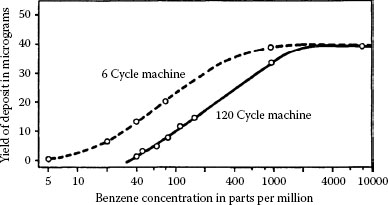
FIGURE 7.52
Yield of frictional polymer as a function of concentration of benzene vapor and wipe frequency. Palladium vs. palladium: 30 gf, 6 Hz and 120 Hz, 170 μm wipe, 4 × 10⁶ cycles. (After HW Hermance, TF Egan, Bell Syst Tech J 37: 739–777, 1958 [104].)
The data of Figures 7.39 and 7.42b illustrated observations that the amplitude of fretting displacements influences contact resistance but that these effects may lead to conflicting contact resistance trends, that is, the time required to reach a selected contact resistance value generally increases but it may also decrease with increasing fretting amplitude. Conflicting trends can only stem from differences in the mechanisms responsible for the generation of metal debris and oxidized metal detritus for different materials in sliding. On this premise, the effects of fretting displacement amplitude on contact resistance may be expected to depend on chemical properties of the surfaces in contact, such as susceptibility to oxidation, and on physical properties such as metallurgical structure and surface hardness, as well as on the thickness of the mating materials. Contact resistance trends also depend on the contact resistance value that defines the “time or number of cycles to reach this value.”
Figure 7.53 shows the number of cycles to reach a contact resistance of 0.1 Ω, 1 Ω and 10 Ω from fretting of tin–lead on the same alloy, plotted against wipe length from 10 to 240 μm [180]. On the 0.1 Ω curve, the number of wiping cycles to reach 0.1 Ω was found to increase with increasing wipe amplitude. This initial trend is thus similar with the data of Figure 7.39 for tin–tin contacts. For displacements that far exceeded those indicated in Figure 7.39, the time required to reach 0.1 Ω (and 1 Ω, 10 Ω) increased with increasing wipe distance in conflict with the data of Figure 7.39. It is likely that other factors such as metallurgical structure and hardness were responsible for the difference in the trends of contact degradation rate for large wipe displacements.
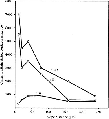
FIGURE 7.53
Number of fretting cycles vs. distance of wipe for Sn60Pb40 vs. Sn60Pb40 required to attain 0.1 Ω, 1 Ω, and 10 Ω: 50 gf, 8 Hz. (After M Antler, IEEE Trans Components, Hybrids, Manuf Technol, 7: 129–138, 1984 [180].)
Results also showing a decrease in the time required for contact resistance to increase to 0.1 Ω, as the wipe amplitude was increased, were obtained in frictional polymerization studies with palladium–palladium contacts [125,174]. The data are shown in Figure 7.54 and were collected under dry and lubricated conditions under test conditions similar to those associated with the data of Figure 7.53. The data of Figure 7.54 are easy to understand since the formation of frictional polymers aligned along the sliding direction is presumably enhanced with increased reciprocating displacement. The typical appearance of the frictional polymers formed under these conditions is shown in Figure 7.55a. Frictional polymer formation rates may be greatly enhanced by depositing a thin layer of an organic material on one of the palladium surfaces before reciprocating sliding, as shown in Figure 7.55b.
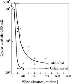
FIGURE 7.54
Number of fretting cycles vs. distance of wipe for palladium–palladium contacts required to attain 100 mΩ: 50 gf, 8 Hz. Data for unlubricated surfaces and for flats lubricated with polyphenyl ether obtained by immersion in a 5 wt% solution of 1,1,1-trichloroethane. (After M Antler, ASLE Trans 26(3): 376–380, 1983 [174].)
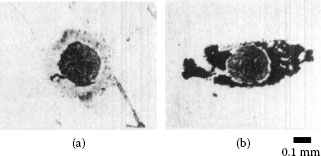
FIGURE 7.55
Optical micrograph of frictional polymers associated with the data in Figure 7.54: (a) unlubricated flat and (b) flat lubricated with a thin film of synthetic hydrocarbon obtained by immersion and withdrawal from 0.5 wt% solution in 1,1,1-trichloroethane. (After M Antler, ASLE Trans 26(3): 376–380, 1983 [174].)
The fretting data presented above makes it clear that contact resistance degradation rates due to the amplitude of fretting displacements cannot be predicted unambiguously. However, the data also suggest that if the contact resistance increase is to be maintained smaller than about 100 mΩ, fretting displacement amplitudes must be maintained smaller than a few to several micrometers.
The rate of contact degradation due to fretting corrosion generally decreases with increasing contact load [150,180]. The influence of an increased force on contact resistance in fretting interfaces can be understood if the larger force enhances penetration of fretting corrosion products or of frictional polymers. In addition, a larger area of mechanical contact subjected to interfacial displacement is more effective in dispersing surface insulating layers, and thus is less prone to entrapping electrically insulating particle debris than a relatively small contact area at smaller loads. Figure 7.56 presents the results [180] of tests with tin–lead fretted on itself from 30 to 300 gf. Although there is data scatter, the trend indicates increasing stability of contact resistance with increasing contact force. However, even at 300 gf, the resistance to fretting corrosion of tin–lead sliding on tin–lead is relatively low.
In a sliding interface, an increased contact force leads to a larger friction force, which in turn resists motion and mitigates the formation of fretting corrosion products. The data of Figure 7.57 were obtained by forcing motion, even at the largest loads. In a connector, raising normal load increases retention force, and the tendency to fret is thereby reduced. This is why highly loaded base metal contacts can be electrically satisfactory when stresses occur that might otherwise cause micromotions. However, large normal loads cannot usually be designed into wiping connectors having many contacts because of the large engagement forces and wear that result.
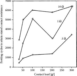
FIGURE 7.56
Number of fretting cycles for Sn60Pb40 vs. Sn60Pb40 required to attain 0.1, 1, and 10 Ω as a function of load: 20 μm wipe, 8 Hz. (After M Antler, IEEE Trans Components, Hybrids, Manuf Technol, 7: 129–138, 1984 [180].)
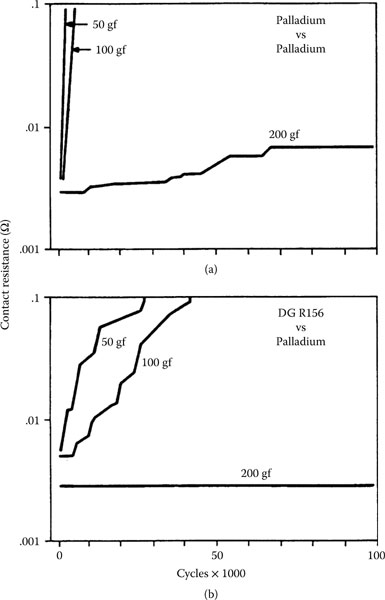
FIGURE 7.57
Contact resistance from fretting of (a) solid palladium and (b) DG R-156 mated to palladium electroplate as a function of load. The palladium electroplate was 1.5 μm thick on 1.25 μm nickel. Data are worst-case results from four runs at each condition. Contact resistance was stable at 200 gf, especially with DG R-156, compared to runs at lower load: 20 μm wipe, 8 Hz. (After M Antler, IEEE Trans. Components, Hybrids, and Manufacturing Technology CHMT-8: 87–104, 1985 [195].)
The effect of load on the contact resistance of palladium-based contacts is presented in Figure 7.57 for palladium–palladium and DG R-156-palladium [195]. The data describe the results of four runs made at a contact force, respectively, of 50, 100, and 200 gf with the two pairs of materials. Figure 7.57a shows Unstable Type I contact resistance behavior at 50 and l00 gf, and Stable (Type III) behavior at 200 gf. Thus, the palladium versus palladium system is similar to the tin–lead versus tin–lead couple at low load, yet it is superior at high (200 gf) load. This suggests that the resistance to penetration of frictional polymers is appreciably smaller than that of surface oxides on tin–lead, although the mechanical deformability of tin–lead plate should facilitate disruption of foreign films. Thus, provided the restriction of moderately high-load contacts is acceptable, it may be possible to design electronic connectors with reliable all-palladium contacts. Systems having DG R-156 on one member are superior to all-palladium contacts from 50 to 200 gf (Figure 7.57b).
In summary, the data of Figures 7.57 and 7.58 illustrate vividly the beneficial effects of increasing the contact load for mitigating electrical contact degradation in fretting contacts. However, in practice, these beneficial effects must be weighed against possible undesirable consequences of a larger contact load, such as larger-than-tolerable increases in retention force and connector dimensions. For example, the use of a large normal force often cannot be accommodated in a multi-pin connector because of the ensuing large engagement force.
The frictional polymer-forming tendencies of various organic vapors in palladium–palladium fretting were studied by various workers [104,170,171,172]. Most organics including those that outgas from the plastic fabrication materials of electronic components can form frictional polymers in reciprocating sliding [136].
The presence of moisture can have a significant but complicated effect on the fretting behavior of electrical contacts. This stems from the reactivity of many metals with water to form oxides form and hydroxides, and hence the susceptibility of these metals to form electrically insulating particle debris in a sliding interface. We illustrate the effect of humidity on the fretting behavior of tin-plated contacts as investigated in the range of dry air to 80% RH [196]. The change in contact resistance of copper contacts as a function of fretting cycles (reciprocating frequency 50 Hz) obtained at various RH is shown in Figure 7.58. These data indicate clearly that the time to reach a selected threshold failure value for contact resistance increases with increasing relative humidity. The data also show that the evolution of the contact resistance consists of three main features: (i) a first phase characterized by a decrease in contact resistance to values often smaller than 10 mΩ and stemming from dispersal of initial surface insulting films, (ii) a second phase where contact resistance remains small and relatively constant with increasing reciprocating cycles, and (iii) a last third phase where the rate of contact degradation increases significantly due to increased wear debris generation and ensuing buildup of electrically insulating material, and galvanic corrosion.
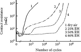
FIGURE 7.58
Contact resistance versus number of fretting cycles in copper–copper contacts under various conditions of relative humidity; 0.5 N, 50 Hz, μm fretting amplitude. (After JF Bruel et al., Proc. 14th Int. Conf. on Electrical Contacts, Paris, France, 1988, pp. 219–223 [196].)
The increasing delay in the onset of the last phase with increasing relative humidity is attributed to the increasing lubrication effect of moisture, which reduces adhesion and thus mitigates mechanical wear. As already mentioned, the rapid electrical degradation in the last phase under each of the conditions 1, 2 and 3 in Figure 7.58 stems from the access of debris from galvanic corrosion products into the electrical contact regions. This increases surface separation and introduces material of higher electrical resistivity into the sliding interface.
It was earlier shown (Figure 7.37) that solid silver does not degrade in air due to fretting. However, if the environment contains a high concentration of gaseous pollutants which can tarnish silver, such as hydrogen sulfide and chlorine at elevated relative humidity, then films may form so rapidly that fretting corrosion occurs. This was demonstrated in a laboratory test at a low cycle rate and relatively small contact normal load [92] using the Battelle Class III flowing mixed gas atmospheric test (see Section 3.3.5). At higher loads and higher fretting velocities, there was little or no effect from these pollutants [116].
The extent of fretting corrosion can be expected to vary with temperature if there is a change in the physical properties of the contact metals or protective lubricant coatings that may be used. A significant change in oxidation rate or other film-forming reactions will also affect the contact behavior. This has been of interest in the automotive sector for under-hood connectors. Figure 7.59 shows the number of cycles to failure [197] at particular test conditions for tin-plated contacts. It was concluded that with rising temperature to about 60°C, an increase in the oxidation rate of tin was responsible for the reduction in cycles to failure. At a still higher temperature of 110°C, the tin softened. This resulted in an enlargement of the contact area, confirmed from an examination of samples after test, with subsequent improvement in fretting corrosion behavior. The illustrative data in Figure 7.59 confirm observations of the effects of increasing temperature on fretting corrosion in tin contacts by other workers [122,197,198,199,200] and in more recent investigations [150].
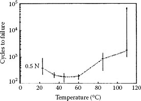
FIGURE 7.59
Cycles to failure as function of temperature as derived from fretting corrosion characteristics at 50 gf. Failure is defined by the contact resistance attaining 20 mΩ for the first time; 20 μm track, 10 Hz; 3-μm tin plate on C65400 copper alloy. (After A Lee et al., Proceedings of the IEEE Holm Conference on Electrical Contacts, pp 87–91, 1988 [197].)
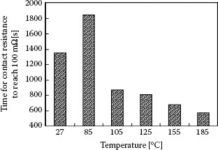
FIGURE 7.60
Time required for the contact resistance to reach a threshold value of 100 mΩ at various temperatures in tinplated copper contacts; 0.5 N, ±90 μm track; 10 Hz; humidity: 55% RH; 0.5 A.). (After YW Park et al., Tribology International 41: 616–628, 2008 [150].)
The formation of intermetallic compounds (IMCs) between tin and the substrate material, such as copper or a copper alloy, may delay the deleterious effects of fretting corrosion at elevated temperatures if the intermetallics grow as a reasonably uniform layer. This effects stems from the high hardness of Cu–Sn IMCs formed at elevated temperatures. A thick intermetallic layer increases the number of cycles required for the rider to penetrate the intermetallic compound and reach the underlying substrate [190]. However, IMCs are notorious for their inferior electrical conductivity properties. The growth of too thick IMCs thus leads to an increase in contact resistance, which may offset the benefits of high hardness. Such effects are shown in Figure 7.60 for tin-plated copper contacts, where the number of reciprocating cycles reach to 100 mΩ, as a function of the temperature at which fretting was carried out between two tin-plated copper surfaces [150]. These data indicate that tin-plated contacts are increasingly less reliable for applications at temperature exceeding about 100°C [189,190,192].
One effect of the passage of current through a contact characterized by high resistance due to the presence of insulating films in the contact is disruption of the films. Disruption of insulating films requires a relatively large voltage drop (generally a few to about 20 V for many insulating layers [3]) across the contact. This magnitude of voltage drop causes electrical breakdown of thin surface oxide or polymer layers, or “fritting.” “Fritting” leads to a rapid decrease in contact resistance due to metal flow through cracks in the disrupted insulating films, and hence formation of metallic conducting paths, even without appreciable current. Such behavior was found in studies at 5 at 14 V with tin [199] plate and at 1 and 2 V with tin–lead-plated [201] contacts. There are, however, contrary results in limited studies with electrodeposited gold [138] and gold-flashed palladium nickel [165] contacts in which a small current, 100 mA, at 10.5 V degraded their performance. Still other experiments [99] showed no effect at dry circuit currents and voltages (100 mA, 20 mV maximum) for some base and noble metal contacts. The range of observed effects of current on contact behavior in fretting are explained in terms of the dependence of the a-spot temperature on the voltage drop across the contact.
The temperature TM of a Joule-heated a-spot is determined by the voltage drop V across the contact in accordance with the relation (see Chapter 1):
(7.4) |
where L is the Lorenz constant (2.45 × 10⁻⁸ V2 K-2) and T0 is the bulk temperature of the bodies in contact (i.e., far from a-spots). Concomitantly, TM is determined by the current. Equation 7.4 applies to all conductors due to the Wiedemann–Franz law which relates the electrical resistivity and the thermal conductivity of metals. The variation of TM with V is shown in Figure 7.61 for values of T0 of 27°C and 100°C. For purposes of illustration, we now consider the sequence of events in contact spots as current is increased across an electrical interface.
For a contact initially at room temperature, an increase in current leading to a voltage drop of less than about 40 mV leads to an a-spot temperature of about 50°C according to Figure 7.61. Such a voltage drop across the contact will have a negligible effect on contact resistance for many contact materials but may lead to a slight decrease in contact resistance in interfaces involving metals such as tin and indium since a-spots in such interfaces may deform relatively rapidly near 50°C, thus increasing the area of true contact. However, because the oxidation rate of non-noble metals increases rapidly with increasing temperature, the imposition of a steady voltage drop of 40 mV involving metals such as tin will activate degradation due to oxidation. In this illustrative example, the dominance of the creep mechanism over oxidation will lead to acceptable contact performance whereas dominance by oxidation will eventually cause catastrophic contact failure. In practice, the dominance of one mechanism over the other will be determined by external factors such as contact load, fretting displacements, and so on.
As current is increased and the voltage drop across a contact exceeds 40 mV, the temperature of a-spots quickly approaches the softening point of the materials in contact. According to the data in Chapter 1, contact asperities of most materials (other than tin) reach their softening temperature at a voltage drop of between 70 mV and 110 mV, corresponding to contact-spot temperature ranging from about 90°C to 150°C. In the vicinity of the softening temperature, the contact asperities of metals flow relatively rapidly and lead to an increase in area of true contact. However, the nefarious effects of thermally activated mechanisms, such as oxidation, interdiffusion, galvanic corrosion, and so on, are also enhanced. In contacts involving noble or near-noble metals such as gold and platinum, the imposition of a voltage drop corresponding to or exceeding the softening temperature will cause rapid interdiffusion of the noble metal either with the underplate material or with alloying elements [202,203] (see Timsit in Chapter 1). For example, the generation of high temperature in hard gold causes migration to the gold surface of hardeners such as nickel and cobalt [203]. This is deleterious to contact stability since nickel and cobalt oxidize readily and may render the gold surface highly susceptible to fretting corrosion.
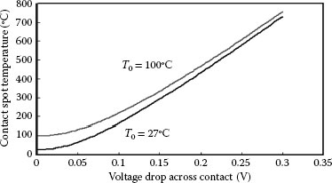
FIGURE 7.61
Dependence of a-spot temperature on voltage drop across a contact (Chapter 1, Equation (1.40).
As current is further increased to generate a voltage drop exceeding 110 mV, the temperature of a-spots approaches the melting point of the materials in contact. According to the data in Chapter 1 (Timsit), contact asperities of most materials reach their melting temperature at a voltage drop of between 130 mV (tin) and 430 mV (copper and gold), corresponding to contact-spot temperature, respectively, of 232°C (tin) 1060°C (gold) and 1084°C (copper). The generation of such large voltage drops in stationary or separable contacts eventually leads to catastrophic failure. Increasing the current to reach a voltage drop beyond the melting voltage first leads to boiling of metal in a-spots, and then to melting and possible boiling of surface layers such as oxides, sulfides, and so on located at spots of mechanical contact.
Figure 7.62 illustrates the degradation of tin–tin contacts subjected to fretting motion but with the contact resistance data recast as voltage drop across the contact, as a function of fretting cycles [204]. The two sets of data were obtained at respective currents of 0.86 A and 0.096 A. The two data sets show an increase in contact resistance, and hence an increase in voltage drop across the contact, with increasing fretting cycles due to fretting corrosion. For the data corresponding to 0.86 A, we note a plateau identified as V at about 130 mV. This plateau corresponds to the melting voltage for tin. Other voltage plateaus that were identified as V2, V3, and V4 were assigned, respectively, to melting of tin oxide, sublimation of SnO2, and vaporization of tin. We note that the voltage range for the second plateau at about 600–700 mV corresponds to the temperature range of l660–1990°C according to the temperature–voltage relation of Equation 7.4. At the smaller current of 0.093 A, thermal runaway did not happen until later during fretting since the generation of a voltage drop of 130 mV required reaching a higher contact resistance than at 0.86 A. Nevertheless, the voltage drop eventually reached the four plateaus V1–V4, as it did at the higher current. Auger depth profiles carried out after recording the data in Figure 7.62 confirmed the predominant presence of tin oxides in contact spots. Data similar to those of Figure 7.62 were reported by other investigators [191,205,206].
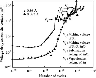
FIGURE 7.62
Voltage drop across the contact versus fretting cycles for two tin-plated copper surfaces, for two different values of electrical current. (After A Lee, MS Mamrick, Hybrids and Manufacturing Technology 10: 63–67, 1987 [204].)
7.3.11 Surface Finish and Contact Geometry
Contact geometry was found [132] to affect the stability of contact resistance of fretting tin-alloy plated surfaces. In this early work, contacts adapted with a 90° or 120° wedge-shaped surface were compared with domed contacts when mated to tin-alloy-plated flats. Motion was mechanically or thermally forced at right angles to the line of contact of the wedge. The resistance of the wedge contacts was more stable than that of the domed contacts. These results were later confirmed in an independent study [198].
In other work, a tin–lead-coated checkerboard surface consisting of rectangular mesa-like high spots, which were about 100 μm on one side alternating with cavities 50 μm deep of similar shape and size, was tested as a model contact surface [207]. This surface geometry led to a Stable (Type III) contact with a consistently low contact resistance. It was suggested that fretting corrosion debris was pushed into the depressions during movement, thereby removing it from the contact surface and allowing the initially low contact resistance to be maintained.
A description of surface finish covers quantification of surface roughness and the characterization of platings and underplates on the surface. Measurements of a direct correlation between initial surface roughness and the evolution of contact resistance under fretting conditions have not been reported. One of the difficulties for such a correlation is the rapid change in surface roughness of a fretted zone even after a few reciprocating cycles [208]. Nevertheless, on the basis of the data shown in Figures 7.15 and 7.16 illustrating the increase in adhesive wear rate with increasing surface roughness, it would be expected that fretting corrosion rates are also accentuated with increased surface roughness.
7.3.12 Material Transfer, Wear, Film Formation, and Contact Resistance
7.3.12.1 Summary of Physical Processes
Contact resistance varies during fretting by a variety of mechanisms involving material transfer, metal removal, and chemical transformations at the sliding surfaces. Many of these mechanisms have been cited in preceding sections, but it is useful to summarize them in order to unify this treatment of contact behavior. Important examples of fretting include the following:
1. Identical contact metals; non-film-forming (e.g., gold versus gold). Gold and high-karat gold contacts form little surface contamination and are generally prone to wear-out (material transfer to a mating surface) and back-transfer from softer mating metals. Material transfer and back-transfer rates are smaller for electrodeposits containing transition metals that originate from gold cyanide baths [65], mostly due the lubricating effect of small polymer particles present in these deposits. Transfer metal becomes work-hardened and few loose wear particles are produced, especially with the ductile wrought forms of this metal. Contact resistance remains relatively stable during fretting and may even fall as the area of contact grows.
2. Identical base contact metals; fretting corrosion (e.g., tin and tin-base finish versus itself and tin–lead solder versus itself). Two series of events can be recognized, depending on whether oxidation happens before or after wear debris forms; first, metal transfer and back-transfer between the surfaces can occur with the generation of occasional particles which then oxidize; and, second, preliminary oxidation of the metal surface, followed by removal of oxide to expose the original surface, which also oxidizes in a repeating process. In both situations, loose oxide accumulates and contact resistance rises.
3. Identical frictional polymer-former metals (e.g., palladium versus palladium). Organic materials are transformed on the surface to frictional polymers under the action of reciprocating sliding. These polymers may be scraped loose. There is little metal transfer and wear. Polymers accumulate and contact resistance increases.
4. Dissimilar contacts; one of the metals forms electrically insulating films. Two examples may be distinguished. Firstly, if the metal that does not form an electrically insulating film is significantly softer than the mating contact material (e.g., gold versus palladium), the base surface becomes covered with the noble metal, thus converting the sliding interface to that described in the above-listed item 1. Secondly, if the metal that forms an electrically insulating film is significantly softer (e.g., tin or tin–lead solder versus gold), an all-base metal system as described in the above-listed item 2 is formed due to metal transfer. The mechanics of oxide film fracture may be less favorable with dissimilar contact metals than when both surfaces are initially identical.
5. Contact material wear-out (e.g., gold-flashed palladium versus itself). Wear and transfer occur with contact resistance determined by the metal originally at the surface. Continued wear-out leading to the appearance of underlying material also leads to a changing contact resistance. Gold-flashed palladium is characterized initially by a low and stable contact resistance, as described in the above-listed item 1, but this is followed by rising contact resistance when palladium is exposed, as in above-listed item 3.
6. Delamination wear. Delamination wear is a mechanism of metal removal that occurs after prolonged fretting in which thin layers are lost by the worn surface to become loose debris.
The capability to predict the effects of changes in operational parameters on fretting corrosion rates from these examples is limited. For example, increasing wipe amplitude may increase metal transfer and wear in some contact materials, and hence increase the quantity of insulating oxide debris that is produced. This leads to contact resistance increases due to oxidized particle pile-up. In contrast, increasing the wipe amplitude in other contact materials may increase the efficacy of oxidized debris dispersal and hence mitigate the rapid buildup of oxidized material in the wear track. This mitigates rapid electrical contact degradation. The effects of frictional polymers on metals can be predicted more reliably than effects of oxidation because transfer and wear are not required for frictional polymer films to form. Decreasing cycle rate increases the time for the deposition of organic matter and thus increases susceptibility to frictional polymer formation on catalytic-type surfaces from lower concentrations of atmospheric organics. Decreasing cycle rate therefore leads to a greater increase in contact resistance for a given number of fretting cycles. Whether dealing with frictional polymer formation or oxidation, increasing the contact force increases material transfer and wear rate and enlarges the contact area. Consequently, more polymers or oxide debris form depending on the contact metal. On the other hand, increasing force enhances the penetration of insulating layers, and on balance, contact resistance diminishes.
In Section 7.4, it will be shown that use of fluid and grease lubricants in electrical contacts reduces base metal transfer, wear rate, wear debris generation, and oxide thickness due to shielding of the mating surfaces from the atmosphere. Lubricants therefore tend to stabilize contact resistance. With catalytic metals, the frictional polymers are readily dispersed in excess lubricant.
Section 7.4 considers the lubrication of separable electronic connectors. Lubrication is broadly defined as the practice of coating contact surfaces to reduce mechanical wear and/or friction, and degradation due to fretting. In electrical contacts, the objective is to preserve the physical integrity of the contact surfaces and to maintain a stable contact resistance.
Lubricants may be described as (1) thin metallic films and organic (2) fluids, (3) greases, and (4) solids. There are still other purposes for some lubricant coatings such as a reduction of the oxidation and corrosion of contact materials, and these will be cited later.
7.4.2.1 Principles of Metallic Film Lubrication
When two touching surfaces are in a relative motion, shearing forces develop leading to surface deformation, friction, mechanical wear, and so on, all of which are affected by surface topography, physical and chemical properties of the materials, the environmental conditions, and other factors. Friction originates from the deformation and shearing of surface asperities [2,5]. Adhesive wear occurs when both the surface and subsurface of mating bodies are subjected to mechanical stresses that lead to material loss. According to the adhesion theory of friction, the frictional force, F, is determined by the shear strength, τ, and the real area of contact, AC, namely , as illustrated schematically in Figure 7.63. For friction force to be low, AC and/or τ must be small. This means that materials associated with low friction should be characterized by high hardness and/or low shear strength. However, this generally is not achievable with monolithic materials; hard metals are generally characterized by high shear strength. However, by using thin layers of soft metallic films on a hard, smooth surface, friction and wear can usually be reduced.
In thin metallic film lubrication, the normal load is supported by the area of true contact and friction is determined by the yield point, p, of the support material and shear strength of the film. The coefficient of friction, μ, is a function of τ/ρ. In practice, a thin, easily sheared metallic film is applied to a hard substrate, and if the surfaces are brought into contact the load will deform the surface asperities of the film but the film will remain supported by the substrate. The area of true contact AC with the film is given as [2,5]
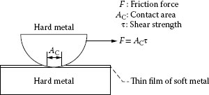
FIGURE 7.63
The friction between metal surfaces can be lowered by depositing a thin film of a soft or easily sheared metal on a hard metal substrate.
where FN is the normal contact force and H is the hardness of the softer of the two materials in contact (H is usually the hardness of the thin metallic film). In electronic contacts where FN is on the order of 0.10 kgf and H of a thin film is on the order of 100 kg mm-2, AC is on the order of 10-3 mm2 and the contact area is thus small. When a tangential force is imposed in a sliding contact, shear takes place easily in the film. Gold is nearly always the thin film metallic lubricant used on electronic connector contacts because it is chemically inert. As discussed later, transition-metal gold-alloy electrodeposits are an exception; they are both relatively hard and easily sheared.
Another requirement of metallic film lubricants is that mating surfaces be relatively smooth and conform well so that the load is supported without major plastic deformation of surface asperities, and little permanent deformation of the substrate. For effective lubrication, there can be no slip between the metallic film and its substrate. Thus, the lubricating film must be strongly bonded so as not to be detached by the shear stresses that develop in the lubricant layer. The extent to which the coefficient of friction can be lowered depends primarily on film thickness, surface roughness, the degree of localized deformation, and the mechanical properties of the film relative to those of its substrate.
7.4.2.2 Sliding and Wiping Contacts
A widely used contact system in telecommunications connectors is illustrated in Figure 7.64. The socket contacts are inlaid with 2.5 μm of DG R-156 and the backplane pin contacts were plated with 1.5 μm of cobalt–gold and lubricated with a polyphenyl ether oil. For cost reduction, it was desired to replace the gold plating with palladium. However, this was not satisfactory, because the palladium plate, although harder than gold, is a poor adhesive wearing material. It displays excessive junction growth, described earlier (Figure 7.8). Since thin gold layers on harder palladium plate were already recognized as capable of providing lubrication function in connectors [63] and on steel in aerospace-bearing applications [209], it was clear that they should be explored further in this application. A bench modeling study [210] was conducted with DG R-156 connector contacts as the rider, and palladium-plated flats were obtained with pure (soft) gold and cobalt (hard) gold platings in a range of thicknesses. A parallel study was conducted with cobalt–gold-plated riders (2 μm thick on 1.25-μm nickel underplate). Both unlubricated and lubricated flats were examined. The lubricant was a polyphenyl ether fluid. Runs were conducted at a load of 200 gf for 200 cycles and a track length of 1 cm. These conditions simulate those of the actual connector.
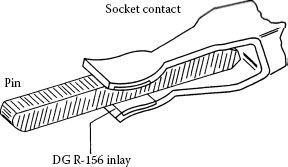
FIGURE 7.64
An individual pin–socket contact from an electrical connector consisting of a pin plated with gold or with palladium having a thin gold overplate and a socket contact with DG R-156 inlaid on the springs. (After M Antler, M Feder, IEEE Trans Components, Hybrids, and Manufacturing Technology 9(4): 485–491, 1986 [210].)
Figures 7.65 and 7.66 are the friction data from this study. Figure 7.67 shows surfaces from some of the worn flats after 200 reciprocation cycles. Figures 7.68 and 7.69 are plots of wear track depth on the flats determined using a profilometer, also after 200 recipro-action cycles. For this system, it was clear that gold layers could be effective lubricants, and that there was an optimal (“critical”) layer thickness of about 0.05 μm for minimal friction and wear. Thicker coatings, especially of pure gold, were characterized by higher friction, stemming from sliding on the bulk gold rather than from shear of a thin layer supported by the hard substrate. Furthermore, the cobalt–gold coating was found superior to the pure gold coating. This is illustrated in Figure 7.67. Although the micrographs in Figure 7.67a and b relate to relatively thick metal coatings, thus not optimized for metal-film lubrication, the difference in the wear marks from unlubricated sliding after 200 passes illustrate the inferior lubrication properties of palladium plate compared to cobalt–gold plate.
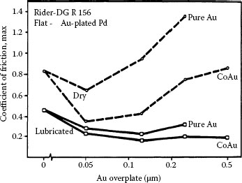
FIGURE 7.65
Relationship between the maximum values coefficient of friction in runs with DG R-156 coated riders versus gold on palladium-plated coupons (using a nickel subplate). The variables were the type of gold plate (either pure or cobalt-hardened) and its thickness, and whether the flats were dry or were lubricated with a thin layer of a polyphenyl ether fluid. (After M Antler, M Feder, IEEE Trans Components, Hybrids, and Manufacturing Technology 9(4): 485–491, 1986 [210].)
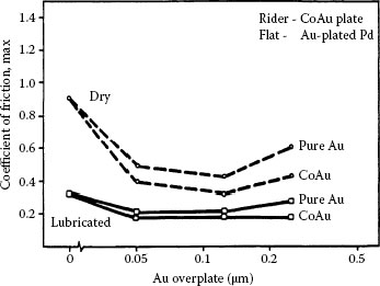
FIGURE 7.66
Dependence of the coefficient of friction on the type of gold overplate on the palladium-plated flat and on whether the surfaces were dry or were lubricated with a thin layer of polyphenylether fluid. Cobalt–gold-plated riders were used for comparison with the data in Figure 7.67 with DG R-156 coated riders. (After M Antler, M Feder, IEEE Trans Components, Hybrids, and Manufacturing Technology 9(4): 485–491, 1986 [210].)
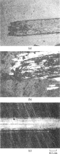
FIGURE 7.67
Wear of plated flats after 200 reciprocation cycles, from unlubricated sliding against DG R-156-coated riders plated with (a) 1.5-μm cobalt–gold on 1.25 μm of nickel underplate or (b) 1.5 μm palladium on 1.25 μm of nickel underplate. (c) Same as (b), but coated with 0.05 μm pure gold on the palladium and lubricated with a thin layer of a polyphenyl ether fluid. Note the more severe wear of the palladium (b) compared to gold (a) and the effectiveness of a gold flash and a fluid lubricant in reducing wear. (After M Antler, M Feder, IEEE Trans Components, Hybrids, and Manufacturing Technology 9(4): 485–491, 1986 [210].)
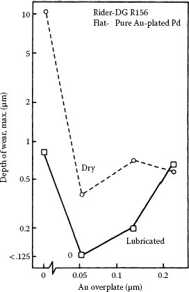
FIGURE 7.68
Wear of flats plated with a 1.5-μm-thick palladium plate on 1.25 μm of nickel from dry and lubricated sliding against DG R-156 riders, after 200 reciprocation cycles. The thickness of the pure gold overplatings on the flats was varied from 0 to 0.25 μm. Wear is expressed as the depth of the deepest scratch from three parallel traversals across the track using a profilometer. (After M Antler, M Feder, IEEE Trans Components, Hybrids, and Manufacturing Technology 9(4): 485–491, 1986 [210].)
The data of Figures 7.65 and 7.66 are explained briefly as follows: at small film thicknesses, lubrication by the metal film is negligible because it is too thin and too patchy to affect the shear strength of the interface with the substrate material, and friction remains high; with increasing film thickness, the low film shear strength begins to influence the shear strength of the sliding interface and the friction coefficient decreases. Minimum friction is reached where the film is sufficiently thick that ploughing friction begins to be significant. Beyond this point, friction continues to increase with increasing film thickness since ploughing friction becomes dominant.
The value of a supplementary organic lubricant to a metallic “lubricant” film was also demonstrated, as shown in Figures 7.65, 7.66 and 7.67c [210]. Commercial exploitation of the cobalt–gold-flashed, palladium-plated connection was made with a 2% coating of a six-ring polyphenyl ether fluid.
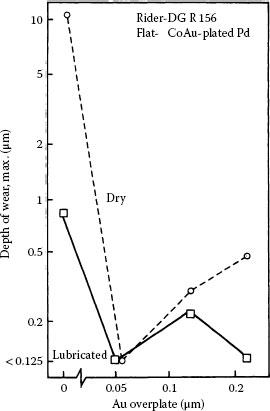
FIGURE 7.69
Wear of palladium-plated flats from dry and lubricated sliding against DG R-156 riders, after 200 reciprocation cycles. The palladium platings were overplated with various thickness of cobalt–gold. These experiments were similar to those relating to Figure 7.68 in which pure gold overplatings were used. Note that the maximum depth of the wear tracks was equal to or less with cobalt–gold than where pure gold was used. (After M Antler, M Feder, IEEE Trans Components, Hybrids, and Manufacturing Technology 9(4): 485–491, 1986 [210].)
Additional examples of the use of thin-film gold lubricant coatings for wiping contacts are for electrodeposited palladium–nickel [165,167], palladium–silver [157], tin–nickel [64], ruthenium [211], rhodium [62], nickel and nickel–phosphorus [212], and for clad noble metals [213]. Developments with thin gold plate on various metals are summarized in [214].
Guidelines for the use of flash gold platings on common contact materials in typical electronic connector are as follows:
1. Substrates and underplatings should be smooth and hard. Nickel underplate at a thickness of 2–3 μm is effective in improving durability.
2. The thickness of the contact finish when combined with the gold overplate should be sufficient to (a) resist corrosion in the environments of interest and (b) mitigate instability of contact resistance due to substrate or underplate diffusion in elevated temperature applications. It may be necessary to avoid porous deposits when the contacts are to be used in aggressive atmospheres.
3. Although pure gold may be employed as a metallic film lubricant, cobalt–gold is preferred to pure gold. A 0.05 μm thickness is adequate.
4. All deposited metal layers should be adherent, consistent with good plating practices.
5. A supplementary fluid lubricant is desirable in order to achieve the lowest friction and to maximize durability.
Because of concerns that frictional polymerization can seriously limit the application of palladium, palladium–nickel, and other catalytic metals in connectors, there has been interest in exploring means for inhibiting polymer formation. If gold is mated to palladium (which is harder), as discussed earlier, the connection behaves as though it were all gold because of the transfer of gold to palladium during fretting. This effectively arrests the formation of deleterious polymers, and was found to be a method for utilizing palladium contacts in wire spring telephone relays in the 1970s and 1980s. In such contact assemblies, one of the palladium contacts required a thick coating of gold or high-gold alloy so that gold transfer to the opposite initially bare surface did not deplete the available gold. Coatings of Au75Ag25 and Au69Ag25Pt6 with a thickness as large as 20 μm have been used for this purpose [215]. Unfortunately, the commercial use of such thick gold-alloy layer can no longer be contemplated in light of the high price of gold. Thin gold films, say, less than 0.25 μm, are relatively ineffective in controlling frictional polymerization on these catalytic substrates since the large number of fretting cycles in many applications leads to the relatively early wear-out of gold. This has already been discussed on earlier and Figure 7.49. However, thin gold films may be used on contacts made from palladium or palladium alloys if the number of fretting cycles expected in service is not expected to be large.
Another example is illustrated in Figure 7.70 [195], from work that was part of the development of a telephone connector (Figure 7.64). In this case, the effects of fretting modeled in the laboratory using gold-flashed palladium mated to itself were compared with those in unlubricated palladium–palladium contacts. The data indicated that the gold flash on palladium only marginally improved its fretting behavior. It was necessary to employ a fluid lubricant together with the gold flash in order to achieve acceptable performance. Fluid lubricants are discussed more fully later. Subsequent studies with gold-flashed palladium–nickel electrodeposits have shown it to have behavior similar to that of gold-flashed palladium [165,216].
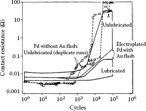
FIGURE 7.70
Contact resistance from fretting of samples with pure gold flash on 1.5-μm palladium having a 1.25-μm nickel subplate mated to itself, clean and lubricated with a polyphenyl ether obtained by immersion and withdrawal of both contacts from a 0.5% solution in a volatile solvent. All data from four replicate runs at each condition fall within their respective bands. Data for duplicate runs with unlubricated palladium without gold flash is indicated by dashed lines. The gold flash had limited durability under the test conditions. Contact resistance was more stable when fluid lubrication was used: 50 gf, 20 μm wipe. (After M Antler, IEEE Trans. Components, Hybrids, and Manufacturing Technology CHMT-8: 87–104, 1985 [195].)
The use of fluid lubricants on connector contacts is by no means universal. When few connector insertions are required and wear is of little concern, there generally is no need to lubricate. This is because exposure to the atmosphere and ordinary handling may deposit sufficient adventitious contaminations to provide adequate protection. This is illustrated in Table 7.3, which shows results of an earlier laboratory study [217] that examined the onset of severe wear in sliding contacts that had been exposed to air in several locations of the same building. It was found that severe wear was initiated after as few as four reciprocation cycles in some connectors to more than 200 cycles in other contacts. In Figure 7.2, the scanning electron micrograph of a typical contaminated gold surface was shown. In the work reported in Table 7.3 [217], contamination occurred relatively quickly due to the absence of shielding of the exposed connector surface. For the connectors investigated, the variability of natural contaminations, the need with multicontact connectors for significant reduction of insertion force, and the large number of required engagements with associated risks of wear-out, eventually led to the intentional use of fluid and grease lubricants to achieve acceptable performance [217]. It is worth recalling that the practice of lubricating electrical contacts is as old as the earliest developments of electrical connectors [218].
Some commonly used lubricants that were originally intended for applications other than in connectors have often led to highly unsatisfactory results. Examples of such lubricants are silicone fluids and water-soluble polyalkylene glycols. The former are incompatible with many metals, and furthermore can contaminate nearby exposed relay contacts with disastrous consequences [219] (see Chapters 10 and 19); the latter “contact enhancers,” not only are poor lubricants [75] but also can corrode metals, although they may have a temporary beneficial effect in reducing contact resistance [220,221]. These comments apply as well to greases and solid lubricants that have been used for connectors.
7.4.3.2 Some Fundamental Properties of Lubricants
In separable electronic connectors where contact surfaces slide at relatively low speeds and lubricant viscosity is low, the action of a lubricant layer occurs via boundary lubrication [2,222]. In boundary lubrication, lubricant layers are adsorbed or chemisorbed on one or the two mating surfaces and are subsequently squeezed to a thickness of molecular dimensions as the surfaces slide over one another. The small shear strength of the squeezed fluid films leads to reduced friction.
TABLE 7.3
Effect of Atmospheric Contamination on Sliding: Cycles to Onset of Severe Wear
Exposure |
|||
Location |
22 Days |
222 Days |
222 Day Samples After 350 h at 50°C |
Humidity-controlled room |
4 |
4 |
4 |
Chemical laboratory |
8 |
95 |
37 |
Telephone switching equipment room |
14 |
>200 |
42 |
Conditions: DG R-156 inlay flats; cleaned; then exposed before wear test in several locations. Sliding versus cobalt–gold-plated riders at 100 gf on a 1-cm-long track until a coefficient of friction of 0.4 was reached.
The efficacy of lubrication has been explored as a function of the lubricant thickness down to sub-monolayer levels. Many of these investigations have relied on ultra-high vacuum techniques and low temperatures to allow both controlled lubricant-layer deposition and the subsequent characterization of the interaction of the layers with the substrate using surface analytical techniques [223 and references within, 224]. Figure 7.71 shows results that typify observations in such investigations. In this example, the static friction coefficient was measured between two sliding Cu(111) surfaces modified by adsorbed layers of 2,2,2-trifluoroethanol (CF3CH2OH) [223]. The coverage of CF3CH2OH ranged from 0 to 14 monolayers (ML) on each Cu(111) surface at a temperature of 120 K. At lubricant coverages <1 ML, the friction coefficient between the surfaces was observed to be very high (> 4). It was only when the lubricant coverage on the two surfaces reached or exceeded 1 ML that the chemisorbed layers acted as a lubricant and friction began to decrease. Ultimately, the friction coefficient fell to a limiting value of ~0.3–0.4 for an accumulation of approximately eight molecular layers of the lubricant.
The formation of a-spots between two lubricated surfaces in an electrical contact must begin with a reversal of the mechanism associated with the data of Figure 7.71, whereby bulk lubricant is first displaced from contacting regions so that only a few molecular layers of residual lubricant remain in the contact, as the contact load is increased. Furthermore, experimental observations that the use of lubricant in a clean or otherwise stable electrical contact has a negligible effect on contact resistance [225] (e.g., see also Figure 7.70) suggest that an appropriate electrical contact lubricant is one where molecules can be totally squeezed out of a-spots to allow metal–metal contact. In this way, the lubricant layers do not interfere significantly with electrical current flow in the contact. It is worth pointing out that displacement of large lubricant accumulations may not occur in an electrical contact if the sliding speed is sufficiently large because the lubricant causes hydrodynamic lift in this case [41].
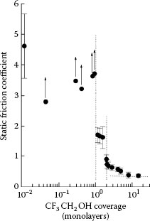
FIGURE 7.71
Static friction coefficient between two Cu(111) surfaces lubricated by thin layers of 2,2,2-trifluoroethanol (CF3CH2OH) versus the CF3CH2OH coverage. The data points with vertical arrows at a coverage of less than 1 ML are also averages of 10 measurements but represent lower limits of the static friction coefficients. Load ≈ 40 mN, sliding velocity = 1, 2, or 3 μm/s, temperature = 120 K. (After AJ Gellman, JS Ko, Tibology Letters 10: 39–44, 2001 [223].)
Starting in the 1990s, computer simulations of the behavior of molecular films in a squeezed confined interface, and attendant experimental work, have provided information on mechanisms responsible for the displacement of thin lubricant films from a-spots in an electrical contact. Typical results of these simulations are illustrated in Figure 7.72 [226]. The data show views of the calculated atomic and molecular configurations at different times during molecular dynamics (MD) simulations of the sliding process of two rough Au(111) crystal surfaces with an entrapped hexadecane layer. Each of the two gold surfaces carries a single asperity, with a height of only six atom planes. The displacement sequence (a) to (f) shows the calculated asperity deformation and the attendant expulsion of the hexadecane molecules as the asperities collide. The behavior of the lubricant thin film in the narrow interface in Figure 7.72 stems from the loss of isotropy of the liquid film in the vicinity of the gold surfaces due to forces originating in the solid surfaces [227]. This leads to oscillatory solvation forces when the surfaces are pressed together, accompanied by a series of layering transitions, each corresponding to a stepwise decrease in film thickness by the expulsion of a discrete amount of liquid lubricant.
Experimental work has confirmed some major results of MD simulations. For example, Figure 7.73 shows snapshots of the contact area between two crossed mica cylinders entrapping a thin layer of 1-undecanol (C11OH) lubricant [227]. The diameter of the contact area is about 100 μm. In images (a) to (f), the contact load is steadily increased from 0 to about 20 mN and the darker color corresponds to smaller film thickness. The micrographs show clearly that as the contact load is increased the dark area (from which the lubricant has been expelled) increases, while the remaining light-colored area (i.e., the remaining trapped lubricant) decreases. The dark area is delineated by the white-dashed curve. The decreasing light-colored area reveals steady expulsion of lubricant molecules from the contact region and relates to a specific layering transition undergone by the trapped fluid.
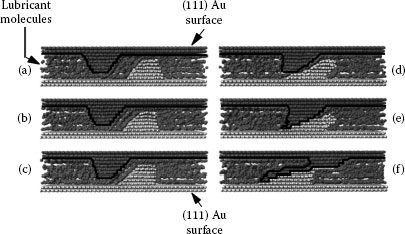
FIGURE 7.72
Side views of the atomic and molecular configurations at different times during molecular dynamics (MD) simulations of the sliding process of two rough Au(111) crystal surfaces with an entrapped hexadecane layer. The profile of the upper gold contact surface is delineated in black. The lower gold surface is shown in light gray. The two gold surfaces carry a single asperity each, with a height of only six atom planes: (a) the two asperities on the sliding gold surfaces are approaching each other, trapping, and starting to squeeze the hexadecane layer to a smaller thickness between them; (b) the two asperities are beginning to deform due to the shear force transmitted by the thin hexadecane film trapped between them; (c) same as (b) but the asperities undergo additional deformation; (d) the asperities are in contact and are severely deformed, and begin to squeeze out hexadecane molecules from the contact; (e), (f) continued severe deformation of the asperities with total expulsion of hexadecane from the contact. (After J Gao et al., Science 270: 605–608, 1995 [226].)
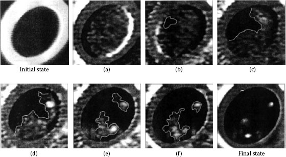
FIGURE 7.73
Snapshots of the contact area between two crossed mica cylinders entrapping a thin layer of 1-undecanol (C11OH). The diameter of the contact area is about 100 μm. In images (a) to (f), the contact load is steadily increased from 0 to about 20 mN. Darker color corresponds to smaller film thickness. As the contact load is increased, the dark area located within the contact region and delineated by the white-dashed curve, increases while the remaining light area (i.e., the remaining trapped lubricant) decreases. The decreasing light area reveals steady expulsion of lubricant molecules from the contact region. (After F Mugele, M Salmeron, Phys. Rev. Letters 84: 5796–5799, 2000 [227].)
The data in Figure 7.71, Figure 7.72 and Figure 7.73 indicate that effective lubrication in a squeezed interface can be achieved with as little as one lubricant molecular layer, and that lubricant films can be expelled from the interface under a sufficiently large contact pressure. Clearly, these observations explain why it is possible to generate metal–metal a-spots in a lubricated electrical contact.
This section briefly summarizes the requirements of a lubricant, methods of application, and provides examples of widely used fluids in current practice.
Fluid lubricants for connector contacts are used nearly always as thin layers. Coverages range from 10–1,000 μg cm−2, which correspond to thicknesses of the order of 100–10,000 μm (assuming that the layer is uniform), depending on the lubricant density and contact surface roughness. At a small thickness, lubricants that are transparent and colorless in bulk—as is usual—are barely visible.
As indicated earlier, the sliding of lubricated electrical contacts is largely in the boundary lubrication region [2,222], where boundary (interactive surface) effects determine lubricating behavior. Other lubricant properties such as viscosity, vapor pressure, and so on are relevant to issues such as the effectiveness of lubricant deposition and retention on a surface, lubricant spreading, lubricant evaporation, and other factors. This is discussed later.
There are properties that are unassociated with lubricant function, but that are highly relevant to the suitability of a candidate fluid as a lubricant in a connector. One major requisite for an acceptable lubricant is low volatility, especially if the connector is designed for use at elevated temperatures. It is usually impractical to relubricate the connector once it is in service.
A lubricant should also be thermally stable and resistant to oxidation, an especially important consideration for elevated temperature service. Oxidation-inhibiting additives are sometimes used to increase lubricant chemical stability.
Another consideration is surface tension. Thin fluid films may creep and in time may disappear from the contact surface. Contamination of nearby electronic components may occur. Creep rate is also determined by the lubricant viscosity. Low surface energy barrier coatings, such as poly-IH,IH-pentadecafluoroctylmethacrylate, are sometimes applied to relay contacts to protect them from silicone contamination.
A lubricant should not react with any connector component to form intractable solid residues. Some contact metals, especially copper and aluminum, may promote both lubricant degradation and oxidation of the base metal [221,228,229,230]. A related requirement is that the lubricant not soften or otherwise alter the dielectric and other organic materials of construction of the connector and adjacent components.
The lubricant should not interfere with the method for making a permanent connection of a conductor to the contact by soldering, crimping, and so on.
The lubricant should be non-hygroscopic, because such fluids can become conductive, allowing electrical leakage between adjacent contacts and conductors, and hence promoting corrosion.
The lubricant should be able to disperse undesirable solid contaminants on the surfaces, such as wear debris and dusts.
Non-toxicity and dermatologic acceptability are also an obvious requirement.
7.4.3.4 Types of Fluid Lubricants: A Sliding Contact Investigation
The lubrication of base metals, especially ferrous metals, has been much studied. An important mechanism of anti-wear effectiveness with these metals stems from the reaction of additives in inert fluids with the metal to form thin layers of easily sheared solids on the surface. For example, fatty acids produce protective soap films. Other compounds that contain chlorine, sulfur, or phosphorus, decompose at hot spots and react with the sliding surface to form metal chlorides, sulfides, or phosphates that reduce friction and increase the transition load from mild to severe wear by the so-called EP (extreme pressure) mechanism. Both soap formation and EP processes are, however, unavailable for gold and other inert noble metals. Examples of this non-effectiveness was demonstrated in early studies [231] of gold sliding using dilute mineral oil solutions of lauric acid, tricresyl phosphate, and carbon tetrachloride.
Various fluids have been tested, at least preliminarily, as lubricants for gold and other connector contact materials. These range from primary (uncompounded) materials to complex mixtures incorporating antioxidants, viscosity index improvers, detergents, and other additives that are used for mechanical devices. An early study [41] of the lubrication of gold determined sliding characteristics with a number of fluids that were available at the time (1963) including dimethylpolysiloxanes, phenylmethylpolysiloxanes, silicate esters, polychlorotrifluoroethylenes, diesters, fluorinated esters, polyalkylene glycols, chlorinated hydrocarbons, phosphate esters, a polyphenyl ether, petroleum oils, and several metalorganics dissolved in mineral oil. The study was continued in 1987 [217] under slightly different test conditions with additional materials, including another polyphenyl ether, perfluoroalkyl polyethers, and poly-alpha-olefins. Products of unknown composition were excluded from these studies.
The investigation involved initially a determination of the coefficient of sliding friction, wear rate, and contact resistance using solid gold specimens in a rider-flat bench apparatus. Contacts were submerged in the fluids. It was found that the effectiveness of the lubricant depended on its chemical structure and viscosity.
The friction data are summarized in Figure 7.74, which also shows whether contact resistance varied during sliding and the cause of the resistance variations. Noise was found to originate from (1) erratic sliding due to stick-slip, surfaces that became rough due to severe wear, and the presence of wear debris; (2) thick film lubrication where the high lubricant viscosity prevented good metal–metal contact (identified as hydrodynamic lift in Figure 7.74); and (3) the formation of insulating layers from lubricant decomposition products (“non-corrosive film formation" [231]). Figure 7.75 shows photomicrographs of typical worn specimens and profilometer traces across the wear tracks of the flats.
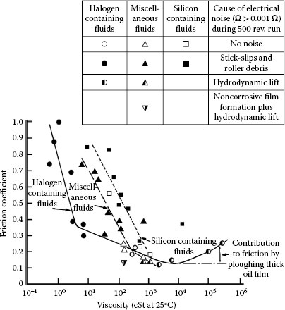
FIGURE 7.74
Coefficient of friction versus viscosity for fluid lubricants. Friction determined near end of 500 rev runs at 100 gf and 1 cm s−1 on 2.5-cm circular track using solid gold contacts. Friction is related both to fluid type and to its viscosity. Electrical noise with poor lubricants is due to hydrodynamic lift or sliding-generated insulating solids which adhere to surface. (After M Antler, IEEE Trans Components, Hybrids and Manuf Technol. 10(1): 24–31, 1987 [217].)
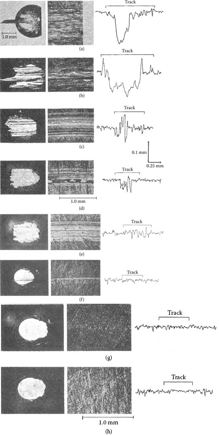
FIGURE 7.75
Photomicrographs of representative worn riders and flats from 500 rev. runs at 100 gf, 1 cm s−1. Stylus profiles made across track: g = Fluorolube LG-160; h = OS-124. Direction of motion or rotating flat: left to right. Poor lubricants (b)–(e) allow metal transfer, prow buildup on rider against the direction of sliding and roughening of flat.
The salient findings are as follows:
1. Halogen-containing fluids are better lubricants than those which incorporate silicon. Oxygen-containing lubricants and hydrocarbons have intermediate behavior.
2. Electrical noise can occur during sliding with fluids characterized by either low or high viscosity; low-viscosity fluids are poor lubricants. High-viscosity fluids promote hydrodynamic separation of the contacts. The viscosities where these effects occur depend on contact normal load, sliding velocity, and other factors. However, the absence of electrical noise during engagement is not normally a requirement of connectors.
3. Lubricants characterized by a favorable combination of thermal, chemical, and lubrication properties for gold-plated electrical contacts include the five- and six-ring polyphenyl ethers and viscous perfluoroalkyl polyethers [232].
Reasons for differences in the effectiveness of lubricants according to chemical class at lower viscosities are not yet established. It is possible that the more effective lubricants are adsorbed more strongly on gold surfaces than those that are less effective.
A key part of the work described in reference [232] was a determination of the time intervals to reach sliding failure of freely exposed contacts that were aged through a range of temperatures in a moving air stream. The results are summarized in Table 7.4 for two polyphenyl ethers. The times to sliding failure in installed connectors would be expected to be longer than those listed in Table 7.4 since a liquid lubricant evaporates less quickly from a mated interface in an installed connector than from contact surfaces that are exposed to open air. High-molecular weight perfluoroalkyl polyether fluids are less volatile than polyphenyl ethers with the same viscosities, but tend to migrate from the contact surface because of low surface tensions. On the other hand, perfluoroalkyl polyether fluids are characterized by viscosity indices that are superior to those of the polyphenyl ethers, that is, their viscosities change less with changing temperature. Both classes of lubricants are characterized by high thermal stabilities to about 290°C for the perfluoroalkyl polyethers and 250°C for the polyphenyl ethers. At temperatures higher than 250°C, five-ring polyphenyl ethers undergo chemical breakdown, which may lead to corrosion of an underlying non-noble metal surface [233].
TABLE 7.4
Calculated Times to Sliding Failures of Contacts Coated with Polyphenyl Ether Lubricants (Years)
Temperature (°C) |
2% Five-Ring Polyphenyl Ether |
2% Six-Ring Polyphenyl Ether |
||
125 |
0.023 |
(8 days) |
0.6 |
(220 days) |
120 |
0.03 |
(111 days) |
0.8 |
(290 days) |
110 |
0.05 |
(18 days) |
2.0 |
|
100 |
0.09 |
(34 days) |
3.8 |
|
90 |
0.18 |
(66 days) |
7.6 |
|
80 |
0.4 |
(148 days) |
17.0 |
|
70 |
0.84 |
(306 days) |
36.0 |
|
60 |
1.8 |
66.0 |
||
55 |
3.0 |
105.0 |
||
50 |
4.4 |
170.0 |
||
40 |
12.0 |
450.0 |
||
30 |
32.0 |
1,200.0 |
||
25 |
62.0 |
2,000.0 |
||
Note: Unmated surfaces in moving air. Sliding at 200 gf for 200 cycles. Cobalt–gold-plated contacts vs. DG R-156 coated with the PPE. Criterion of failure: coefficient of friction of 0.4 which occurs at the transition from mild to severe wear. The times to failure for mated connectors are 2–100 times greater than the values in this table, depending on their design.
An interesting characteristic of polyphenyl ethers is that they do not wet surfaces due to their high surface tension (about 50–54 dynes cm−1 at 25°C). The beading tendency of polyphenyl ethers facilitates visual detection of the lubricant in ultraviolet light if a fluorescent dye [234] in small amount is incorporated in the lubricant–solvent mixture. Polyphenyl ethers represent a lubricant class of considerable interest for applications in many subsequent studies of fretting control, corrosion inhibition, and so on. Other lubricants have come into use as the connector market has grown, but there is relatively less engineering literature on them because of the secrecy that surrounds lubrication practice for electronic connectors.
7.4.3.5 Control of Fretting Degradation
Lubricants can significantly improve the contact resistance behavior of fretting electrical contacts. The amount of lubricant required depends on the contact metals and the mechanism(s) by which they degrade. Also, only fluids and greases are useful; solid lubricants, such as microcrystalline wax, are of little value in fretting because they are quickly displaced from the contact.
7.4.3.5.1 Reduction in Wear Rate
Oxidized metal that forms during the fretting of base metals originates, in part, in loose wear debris. A lowering in wear rate therefore tends to stabilize contact resistance. When the contact finish is gold, a decrease in the wear rate is beneficial since the time until the base underlying metal is exposed is extended. An example of the life extension of a contact under reciprocating displacement through the use of a lubricant is shown in Figure 7.76 [99], in which the contact resistance behaviors of gold-plated copper with and without a lubricant are compared. The lubricant consisted of a five-ring polyphenyl ether.
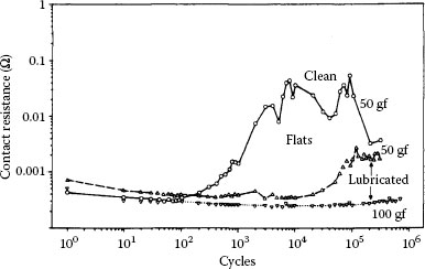
FIGURE 7.76
Contact resistance vs. fretting cycles for solid gold riders against 0.23-μm cobalt–gold-plated copper flats, with and without polyphenyl ether obtained by immersion and withdrawal from a 0.5% solution of the contact lubricant in a volatile solvent: 20 μm wipe. (After M Antler, MH Drozdowicz, Wear 74: 27–50, 1981–82 [99].)
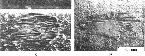
FIGURE 7.77
Worn specimens from fretting with 2.5-μm cobalt–gold electroplate mated to itself: (a) unlubricated; note rough surface and dark region in center which is exposed nickel underplate; (b) coated with polyphenyl ether obtained by immersion and withdrawal from a 0.5% solution in a volatile solvent surface is burnished: 50 gf, 20 μm wipe, 105 cycles. (After M Antler, IEEE Trans Components, Hybrids, Manuf Technol, 7(4): 363–369, 1984 [186].)
Visual confirmation that introduction of the lubricant led to the decrease in gold wear rate indicated in Figure 7.76 is shown in Figure 7.77. In this figure, the optical micrographs compare the surface damage of identical cobalt–gold-plated surfaces that had been subjected to the same fretting wear exposure but that had been, respectively, unlubricated and lubricated [186]. In dry fretting (Figure 7.77a), the gold surface was worn to the nickel underplate whereas the gold surface was only burnished and wear was negligible (Figure 7.77b) with introduction of the lubricant.
7.4.3.5.2 Effect on Frictional Polymerization
Selected lubricants are capable of stabilizing the contact resistance between metals that catalyze frictional polymer formation. Lubricant effectiveness is usually strongly dependent on the thickness of the lubricant, as shown in Figure 7.78 [235]. Some benefit was obtained with palladium–palladium contacts coated with 0.5% of either of the two fluids indicated in the figure; but with thicker coatings from solutions of 2% or greater concentration, the beneficial effect was particularly striking.
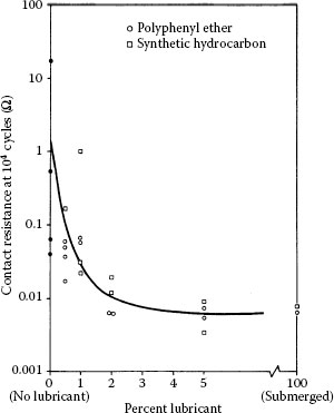
FIGURE 7.78
Contact resistance after 104 cycles of fretting in palladium–palladium contacts as a function of amount of lubricant on the surface. Coatings obtained by immersion and withdrawal of the flat contact in solutions of the lubricants having concentrations of 0.5, 1, 2, and 5% in a volatile solvent, or by placing a drop of lubricant on the mated contacts. Each data point is the result from a single run. Solid circles are data from unlubricated samples. Contact resistance stability is improved with increasing amount of lubricant: 50 gf, 20 μm wipe. (After M Antler, IEEE Trans Components, Hybrids, Manuf Technol, 7(4): 363–369, 1984 [186].)
Another example was given earlier in Figure 7.70 with fretting palladium contacts covered with a gold flash where a five-ring polyphenyl ether coating from a 0.5% solution was used. The maximum contact resistance was three orders of magnitude smaller with lubricant than without it after about 105 fretting cycles, and the initiation of contact resistance rise was also significantly delayed. Probably, the effectiveness of the lubricant was due to both reduction in the rate of wear of the gold flash and contact resistance stabilization once the gold had been worn away to the underlying palladium. It is recommended that lubricants be employed in sliding systems such as gold-flashed palladium, palladium–nickel and other palladium group metals, and more generally in contact interfaces susceptible to rapid degradation by fretting corrosion due to a special or a harsh environment in service.
Figure 7.79 is a striking example of polymer dispersal from a long run with palladium contacts immersed in USP mineral oil [174]. In this case, the polymer debris consisted of a voluminous filmy semi-transparent black solid sheet located alongside the wear scar. The polymer debris was convoluted, which suggests that the frictional polymers were produced continuously during fretting, and that successive slides pushed away the freshly formed material. The polymer film was semi-transparent, which indicates that its thickness ranged from a few tens to hundreds of nanometers thick. It is surmised that the film grew to this thickness on the surface before being pushed aside. However, the film must have been readily penetrated by the mating asperities, since contact resistance was little different during the entire run from the value measured before fretting was initiated [174].
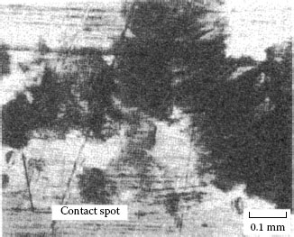
FIGURE 7.79
Frictional polymer from fretting palladium–palladium contacts. Flat lubricated by immersion in USP mineral oil. Lubricant not removed. Note thin-convoluted dark polymer film dispersed in excess lubricant. 50 gf, 20 μm wipe, 5.5 × 10⁵ cycles. (Optical micrograph, after M Antler, ASLE Trans 26(3): 376–380, 1983 [174].)
7.4.3.5.3 Effect on Fretting Corrosion
Lubricants have long been recognized to be effective in inhibiting the increase in contact resistance between base metal surfaces that degrade by fretting corrosion [101,134,135] and an example [180] is given in Figure 7.80 for tin–lead to tin–lead contacts. In this case, a 2-μm coating from a 20% solution of mineral oil in a volatile solvent stabilized contact resistance for at least 105 cycles, whereas a coating extracted from a 5% solution stabilized contact resistance for only ~103 cycles. These data are typical of many findings relating to the dependence of lubricant effectiveness on the quantity of fluid used than on its composition.
Fluids studied for the fretting corrosion problems of tin and tin–lead contacts include mineral oils, poly-alpha-olefins, polyphenyl ethers, polyalkylene glycols, and poly-chlorofluoroethylenes in [180]; and diesters, silicones, and phosphate esters in [134]. In order to achieve uniformity of lubricant distribution in a mated system, it is generally advisable to apply the lubricant to the two contacting sliding surfaces rather than to only one.
7.4.3.5.3.1 Mechanisms The mechanisms by which lubricants act to mitigate an increase in contact resistance during fretting displacements include wear reduction, dispersion of insulating solids, and enhanced shielding the surface from air, thereby retarding the rate of oxide formation. The enhanced resistance to fretting corrosion due to the presence of an appropriate lubricant is illustrated in Figure 7.81 where worn tin–lead surfaces coated with different thicknesses of lubricant are compared. The surface treated with the 20% polyphenyl ether solution is bright, whereas the comparable contact coated with 5% polyphenyl ether is oxide-covered, much like surfaces from unlubricated fretting.
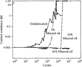
FIGURE 7.80
Contact resistance vs. fretting cycles for Sn60Pb40 vs. Sn60Pb40-plated contacts. Flats lubricated by immersion and withdrawal from 5, 10, and 20% solutions of USP mineral oil in a volatile solvent. The thicker the lubricant layer, the greater the stability of contact resistances: 50 gf, 20 μm wipe. (After M Antler, IEEE Trans Components, Hybrids, Manuf Technol, 7: 129μ138, 1984 [180].)
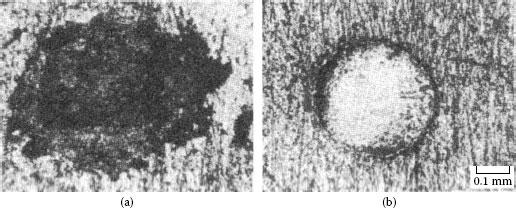
FIGURE 7.81
Lubricated Sn60Pb40-plated flats after fretting against Sn60Pb40-plated riders: (a) coated with 5% polyphenyl ether; (b) coated with 20% polyphenyl ether: 50 gf, 20 μm wipe, 105 cycles. The flat in (a) is covered with an insulating black oxide (contact resistance, 37 Ω) and in (b) the surface is bright (contact resistance, 0.9 mΩ). (After M Antler, IEEE Trans Components, Hybrids, Manuf Technol, 7: 129–138, 1984 [180].)
7.4.4 Grafted and Self-Assembled Lubricant Layers
In extreme environmental conditions such as high vacuum, high temperature, or under conditions of frequent interfacial displacements during extended service where high-lubricant durability is required (e.g., in microelectromechanical systems, aerospace applications, and so on), the use of a liquid lubricant in an electrical contact is often unsatisfactory. This stems from a number of factors such as eventual displacement of the lubricant from the contact region at an early juncture in service, lubricant evaporation, or even crystallization. One possible approach to resolving the problem of lubricant depletion is the use of chemical grafting of lubricant layers to the underlying metal surface. Although there are limitations to the use of grafted lubricant layers for many contact applications, as will be addressed later, the technology is relatively novel and promising and deserves description.
The term “grafting” simply means attaching molecular components to the lubricant molecules (i.e., polymerize the lubricant) to achieve a strong chemical attachment to the substrate, as illustrated schematically in Figure 7.82 [236]. An excellent review of chemical grafting technology is given in reference [237]. Chemical attachment to the solid (also described as “grafting” to the substrate) must not be so strong as to prevent displacement of lubricant molecules during contact to allow a-spot formation. One side benefit of molecular grafting is mitigation of oxidation, sulfidation, and other corrosion reactions of the metal substrate with the atmospheric environment, since the grafted layers minimize exposure of the underlying surface to air.
Although there are several grafting techniques [236,237], electropolymerization is becoming the preferred approach since it also allows deposition of the structurally modified lubricant on the desired surface [238,239,240,241,242,243]. The process of electropolymerization under cathodic polarization consists in starting an acid–base reaction between one end of a monomer in solution and the metallic surface acting as electrode (“grafting” the monomer to the metal). This process is then followed by initiating a reaction between the monomer and the graft (i.e., the lubricant molecule) to start the growth of the molecularly modified lubricant film. An organic layer strongly linked to the substrate is thus obtained, as illustrated schematically in Figure 7.82. The lubricant film thickness may vary from a few nanometers to a few micrometers. Figure 7.83 shows an example of contact resistance properties of polyacrylonitrile layers grafted onto nickel-plated brass. The cumulative values of contact resistance were obtained for a number of samples before and after heat treatment in air under six different conditions with a load of 50 gf [243]. The decrease in contact resistance with increasing treatment temperature was associated with changes in the molecular structure and molecular length of the grafted polymeric structure on the surface [243]. The friction coefficient following some of the thermal treatment conditions are shown in Figure 7.84. These data indicate clearly that optimal results combining low contact resistance and low friction required longer heating at 400°C in this case. Aside from the practical challenge of subjecting connectors to such an elevated temperature to optimize lubricant function, these data also point to one of the limitations of grafted lubricants that their durability may not be adequate where a large number of reciprocating cycles are expected.
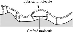
FIGURE 7.82
Schematic diagram of “grafting” molecular components to a lubricant molecule (i.e., polymerization of the lubricant) to achieve a strong chemical attachment to the substrate.
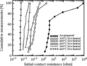
FIGURE 7.83
Cumulative distribution of contact resistance for polyacrilonitrile layers in interfaces consisting of surfaces electroplated with nickel and subjected to six different heat treatments, a contact load of 50 gf. (After F Houzé et al., IEEE Trans Components, Hybrids, and Manuf. Technol.-Part A 18: 364–368, 1995 [243].)
Attachment of a lubricant to a surface may also be achieved by modifying one or more end groups of a lubricant molecule before deposition to increase bond strength to the surface. This technique is also often identified as grafting, but this description is not strictly applicable since the lubricant structure is modified chemically in the absence of the surface for which it is intended. Bare metal surfaces tend to adsorb organic materials readily because these adsorbates lower the free energy of the interface between the metal and the ambient environment [244]. Self-assembled monolayers (SAMs), or self-assembled multilayers, provide a convenient, flexible, and simple system with which to tailor the interfacial properties of metals (as well as metal oxides and semiconductors). SAMs are organic assemblies formed by the adsorption of molecular constituents from solution or the gas phase onto the surface of solids and the subsequent spontaneous organization of the adsorbates into crystalline or semicrystalline structures [245]. The molecules or ligands that form SAMs have a chemical functionality, or “headgroup,” with a specific affinity for a substrate. There are a number of headgroups that bind to specific metals but one of the most extensively studied SAM class is derived from the adsorption of alkanethiols (i.e., sulfur-containing alkanes) on gold, silver, copper, palladium, and platinum [246]. The high affinity of thiols for the surfaces of these metals makes it possible to generate well-defined organic surfaces with useful and highly alterable chemical functionalities displayed at the exposed interface. This affinity is often so high that SAMs of alkanethiols and dialkanethiols on gold are becoming key elements for building many systems and devices with applications in the wide field of nanotechnology, thus extending SAMs to applications beyond those of lubricants on gold [247].
As already mentioned, one of the major current obstacles to the widespread use of grafted or functionalized lubricant layers in practical electrical contacts, at least as regards lubricants for which there exists test data [248,249], is the lack of durability over several millions (or more) reciprocating cycles. Durability of this magnitude is required for most anti-wear or anti-fretting applications in practical separable electronic connectors. The maximum durability of grafted or functionalized lubricants reported so far does not exceed approximately 2 × 10⁵ cycles [250]. For functionalized SMAs, another potential obstacle is the challenge of designing a chemical headgroup that does not promote corrosion under any circumstance. For example, the introduction of a thiol (sulfur) group in selected lubricants raises concerns about possible detachment and subsequent migration of sulfur to underlying copper alloy or Ni materials via pores in the gold, to promote pore corrosion (see Chapters 2 and 8). At present, the most promising applications for grafted and functionalized SMA lubricant layers is in selected MEMS structures where mechanical wear must be minimized and the number of reciprocating cycles during the expected device life may be relatively small.
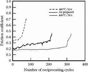
FIGURE 7.84
Evolution of the mean friction coefficient versus the number of reciprocating cycles, corresponding to three of the experimental conditions of polyacrilonitrile layers on nickel shown in Figure 7.83. (After F Houzé et al., IEEE Trans Components, Hybrids, and Manuf. Technol.-Part A 18: 364–368, 1995 [243].)
7.4.5 Greases and Solid Lubricants
Greases are semi-solids consisting of a thickening agent and a fluid lubricant. Many fluids have been incorporated into greases and used in connectors for reducing contact wear and for controlling fretting corrosion. The thickeners include finely divided silica, soaps (sodium, lithium, barium, and other fatty acid salts), clays, Teflon powder, and various gelling agents, usually at 5–10% concentration. Mixtures of fluids and microcrystalline petroleum or synthetic waxes have also had extensive use. Petrolatum is a mixture of microcrystalline wax and mineral oil. Other additives, such as antioxidants, may be incorporated in the grease. Greases that contain graphite, or metallic particles such as zinc or silver, are not used in electronic connectors.
Grease structures are complex, consisting of interlocked fibrous crystallites (Figure 7.85a) or finely divided particles having a large surface area (Figure 7.85b) [251]. The solid component of greases forms a mixture in which the fluid is entrapped.
An advantage of greases is that they retain a fluid on the contact surface, thus minimizing loss by creep. Some “bleeding” may still occur, and, at worst, leave behind the solid phase that can cause the contact resistance of a connector to increase. The solid component must not agglomerate, or else contact resistance may be degraded. Clay- and Teflon-thickened greases have been troublesome, especially for lightly loaded devices; but this was often attributable to deficiencies in the manufacture of the greases rather than in anything fundamental. Greases must not be too hard, since this may interfere with surface asperity mating. “Self healing,” or the ability of flow back to recoat the wear track after a pass, is also less efficient with grease than with the base fluid of the grease [46]. One of the potential hazards of using grease in a separable electronic connector is the inadvertent introduction of copious amounts of corrosion-promoting materials, such as sulfur, since greases contain materials derived from petroleum. The presence of such contaminants defeats one of the main objectives of using grease, which is to protect the contact from corrosive atmospheric pollutants.
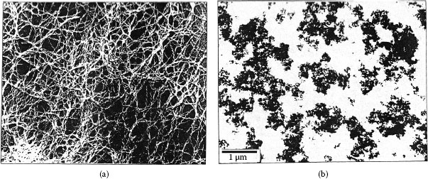
FIGURE 7.85
Grease structures: (a) lithium hydroxystearate; (b) silica base. (After JH Harris, In ER Braithwaite, ed. Lubrication and Lubricants, Amsterdam: Elsevier, 1967, pp 197–268 [251].)
Greases are applied to surfaces by brushing, injection through nozzles, or, for thin coatings, by dilution in a volatile liquid and immersing the contact in the stirred mix. Alternately, the diluted grease may be sprayed with a propellant on the contacts. Agitation is necessary to ensure that the solid, fluid lubricant, and carrier components are uniformly mixed.
The technical literature on greases, their compositions, manufacture, and application, is extensive; but very little has been published that is specific to connectors. A few examples of work with greases from the literature are as follows:
1. Reference [194] used a polyalkylene glycol—10% fumed silica grease to restore tin–lead contacts to service that had failed by fretting corrosion.
2. Reference [74,75] used a halogenated silicone oil gelled with a fluorocarbon polymer to stabilize the contact of fretting tin-plated contacts.
3. Reference [252] evaluated a lithium soap and clay-thickened grease in a switch. Although this was not a connector application, an analysis of contact problems is given.
4. Reference [180] tested greases made from microcrystalline wax with these fluids: polyphenyl ether, polyalkylene glycol, poly-alpha-olefin, mineral oil, and a grease containing a diester, lithium soap, and a synthetic wax in a tin–lead fretting study.
Solid lubricants have generally been unsatisfactory for connector contacts. Graphite burnished on contacts lubricates well but is not sufficiently conductive to assure low contact resistance. Connectors with graphite-lubricated contacts were commercially available at one time [253]. Tough low-friction solids, such as Teflon powder, dusted into contact surfaces are unsuccessful [180].
Microcrystalline wax, which may be viewed as a highly plastic solid, can be used on wiping contacts if the contact surfaces are rough. The wax is entrained into the low spots of the surface roughness, and as the surface becomes smoother through use, the wax lubricates effectively [46]. Once the surface is burnished, any residual wax is displaced from the wear track, and sliding may convert from the mild to the severe regime. Since the porosity of platings increases with initial roughness, the trend to thinner precious metal deposits for economic reasons has increased awareness of the advantage of preparing contact surfaces that are smooth. With this, interest in wax lubricants has essentially disappeared.
As mentioned earlier in relation with grafted and functionalized lubricants, the durability, or persistence of lubricant coatings on contact surfaces, is of concern when many mating cycles are required during the life of a separable connector. Unlike most fluid-lubricated bearings that are adapted with sumps that provide a continuous copious supply of lubricant to the surfaces, electric contact interfaces carry lubricant in thin coatings and thus in highly limited supply. If only a few matings are involved, very thin lubricant layers are generally satisfactory, for example, grafted layers or lubricants layers obtained by dipping from an appropriate solution for both noble and non-noble metal platings [232,248,249,250]. Adventitious contamination is often beneficial if the contaminant is neither corrosive nor chemically reactive with the contact surfaces, and acts as a lubricant. In such cases, and if mating and re-mating does not involve sliding along precisely the same track [254] to disperse or remove the contaminant, the effective supply of adventitious lubricant available to the sliding interface is large and effective lubricant durability is high.
In the case of fretting, however, the numbers of wear cycles may be large, and thin lubricant layers (whether flash gold coatings,fluids, greases or adventitious contaminants) are relatively ineffective. There have been few quantitative studies of lubricant wear-out processes. Operating conditions, contact shape and surface roughness, the contact material, and the physical properties of the lubricant coating determine its persistence. Figures 7.78 and 7.80 illustrate examples from fretting where the effectiveness of a lubricant was related to the amount deposited on the surface.
For materials that are thermally stable and relatively resistant to oxidation, lubricant wear-out stems from evaporation, film creep, and mechanical loss [22,41,232]. Mechanical loss is due to removal by sliding wherein wear debris carries the lubricant away. In the case of solid lubricants such as thin gold layers, the lubricant is lost more directly via layer wear-out and subsequent displacement from the wear track. When chemical effects occur, such as oxidation of the lubricant at excessively high temperatures, the viscosity changes. This leads to sludge formation and even contact corrosion; these mechanisms then conspire to deplete the lubricant supply from the sliding interface.
On the basis of the literature on lubricant durability reviewed above, and the authors' experience, the following recommendations can be made for the required concentration of lubricant in a carrier solvent for forming an acceptably thick layer of residual lubricant on a contact surface by dipping, for a variety of practical electrical contact applications:
1. for wiping and sliding contacts (friction and wear reduction), 1–2%;
2. for fretting (control of corrosion and frictional polymerization), 2–20%;
3. for tarnish and galvanic corrosion inhibition, discussed later, 2–5%;
4. for dispersing particulate matter on the contact (see below), 1–10%.
Thicker lubricant coatings are not deleterious, and neat fluids as droplets or smears of greases, have been used with good results.
7.4.7.1 Dispersal of Particulates
Contamination of contact surfaces by dust can interfere with the formation of a reliable electrical contact. The severity of the deleterious effect of dust relates to the sliding/wiping distance in the connection. Long wipes are more effective in displacing contaminants than short movements, as in fretting. Lubricated surfaces are more prone to entrapping particulates than clean surfaces, and the severity of the resulting problem depends on the physical state of the lubricant. Waxes and greases are more likely to retain particles than fluids, which tend to disperse these contaminations. Dielectric constant also plays a role; lubricants with low constants attract dusts less [255,256,257]. Particle size, normal load, and thickness of the lubricant layer also are variables.
An interesting investigation of the effectiveness of selected contact surface shapes in displacing dust during sliding was reported in [258]. It was found that hemispherical dimples are most effective in dispersing particulate matter such as sand from a sliding connector interface due to the ease with which particles can be shoved aside by a moving hemisphere.
The benefits of organic lubricants in reducing friction and wear and the control of fretting degradations in connectors are well recognized, as discussed earlier. Concurrently, there has been a reduction in the average thickness of noble metals used in connectors because of cost. An increase in electrical contact problems associated with corrosion, and particularly pore corrosion (see Chapters 3, 4, and 8) in thin finishes has resulted in a renewed interest in tailoring lubricants so that they also can inhibit corrosion and tarnishing. Most attention has been directed to the development of lubricants of increased effectiveness on electrodeposited gold finishes.
Observations of the property of petrolatum to reduce the sulfidation of silver appeared in the early contact literature. An expansion of this concept led to the development of a grease consisting of microcrystalline wax and a five-ring polyphenyl ether fluid [259] that turned out to be an effective lubricant and tarnish inhibitor for silver. Sporadic work followed, for example [111,260,261]. A review of several thin coatings and other surface treatments, and their evaluation in a flowing mixed gas corrosion test coupled with other physical studies, are provided in [220]; however, tribological studies were not part of that investigation. Coatings formed from microcrystalline wax and polyphenyl ethers appear to have broad utility. However, these layers must be carefully chosen based on the requirements of the application, especially service temperature requirements. Even more effective coatings undoubtedly can be developed [262] (see the discussion in Section 3.4).
1. E Rabinowicz. Friction and Wear of Materials, ASM, 1981.
2. IM Hutchings. Tribology: Friction and Wear of Engineering Materials, Boca Raton: CRC Press, 1992.
3. R. Holm. The friction force over the real area of contact (in German). Wiss Veroff Siemens-Werk 17(4): 38–42, 1938.
4. RF Tylecote. The Solid Phase Welding of Metals, London: Edward Arnold (Publishers) Ltd., 1968.
5. FP Bowden, D Tabor. The Friction and Lubrication of Solids, Part 1, London: Oxford University Press, 1950.
6. FP Bowden, D Tabor. The Friction and Lubrication of Solids, Part II, London: Oxford University Press, 1964.
7. R Holm. Electric Contacts, Berlin: Springer-Verlag, 1946.
8. E. Rabinowicz, D. Tabor. Metallic transfer between sliding metals: An autoradiographic study. Proc Roy Soc A 208: 455–475, 1951.
9. JF Archard. Contact and rubbing of flat surfaces. J Appl Phys 24(8): 981–988, 1953.
10. JF Archard. Single contacts and multiple encounters. J Appl Phys 32(8): 1420–1425, 1961.
11. IM Feng. Metal transfer and wear. J Appl Phys 23: 1011–1029, 1952.
12. EW Glossbrenner. Sliding contacts for instrumentation and control. In P.G. Slade, ed, Electric Contacts: Theory and Applications, New York: Marcel Dekker, Inc., 1999, p 885.
13. I.H. Brockman, C.S. Sieber, R.S. Mroczkowski. A limited study of the effects of contact normal force, contact geometry and wipe distance on the contact resistance of gold-plated contacts. IEEE Trans Comp, Hybrids, Manuf Technol CHMT-11: 393–400, 1988.
14. T Smith. The hydrophilic nature of a clean gold surface. J Colloid Interf Sci 75: 51–55, 1980.
15. RA Coutu Jr, P.E. Kladitis, K.D. Leedy, R.L. Crane. Selecting metal alloy electric contact materials for MEMS switches. J Micromech Microeng 14: 1157–1164, 2004.
16. JT Burwell, C.D. Strang. On the empirical law of adhesive wear. J Appl Phys 23(1): 18–28, 1952.
17. J.T. Burwell, C.D. Strang. Metallic wear. Proc Roy Soc A 212: 470–477, 1952.
18. J.F. Archard, W. Hirst. The wear of metals under unlubricated conditions. Proc Roy Soc A 236: 397–410, 1956.
19. R. Bruckner, T. Lapham. The effect of cycle rate and lubrication on the wear of electrical contacts. Proceedings of Annual Electronic Connector Symposium, Cherry Hill, NJ: Electronic Connector Study Group, Inc., 1969, pp 351–368.
20. M. Antler. Processes of metal transfer and wear. Wear 7: 181–204, 1964.
21. M. Cocks. Interaction of sliding metal surface. J Appl Phys 33: 2152–2201, 1962.
22. M. Antler. Wear, friction, and electrical noise phenomena in severe sliding systems. ASLE Trans 5: 297–307, 1962.
23. M. Antler. Metal transfer and the wedge forming mechanism. J Appl Phys 34(2): 438–439, 1963.
24. H. Fry, H.G. Feller. Investigation of wear with the scanning electron microscope. Prakt Metallographie 9: 182–197, 1972.
25. K.I. Molanin. In V.D. Kuznetsov, ed, Metal Transfer and Build Up in Friction and Cutting, New York: Pergamon, 1966, p 283 (transl. from Russian).
26. M. Antler. Wear of electrodeposited gold. ASLE Trans 11(3): 148–260, 1968.
27. N. Ohmae, E. Rabinowicz. The wear of the noble metals. ASLE Preprint No. 78-LC-2C-1.
28. S.A. Barber, E. Rabinowicz. Material selection for noble metal slip rings. Proceedings of Holm Conference on Electrical Contacts, Chicago, 1980, pp 33–40.
29. D.H. Buckley. Friction Behavior of Members of the Platinum Metals Group with Gold. NASA Tech Note D-7896, NASA, Langley Research Center, 1975.
30. A.J. Solomon, M. Antler. Mechanisms of wear of gold plate. Plating 57: 812–816, 1970.
31. F.I. Nobel, D.W. Thomson, J.M. Leibel. An evaluation of 18 karat and 24 karat hard gold deposits for contact applications. Proceedings of the 4th Plating in Electronic, Industry Symposium, American Electroplaters’ Society, Indianapolis, 1973, pp 106–130.
32. F.B. Koch, Y. Okinaka, W. Wolowodiuk, D.R. Blessington. Additive-free hard gold plating for electronics applications, Part 1. Plat Surf Finish 67(6): 50–54, 1980.
33. F.B. Koch, Y. Okinaka, W. Wolowodiuk, D.R. Blessington. Additive-free hard gold plating for electronics applications, Part II. Plat Surf Finish 67(7): 43–45, 1980.
34. W.H. Abbott. Precious metal electrodeposits for electrical contact applications. Proceedings of the Symposium on Electrodeposited Metals as Materials for Selected Applications, NTIS, US Dept. Commerce, Springfield, VA, 3–4 November, 1971, pp 32–37.
35. Y. Okinaka, F.B. Koch, C. Wolowodiuk, D.R. Blessington. “Polymer inclusions” in cobalt-hardened electroplated gold. J Electrochem Soc 125(11): 1745–1750, 1978.
36. M. Antler. Wear of gold plate; effect of surface films and polymer codeposits. IEEE Trans Parts Hybrids, Packag 10: 11–17, 1974.
37. Y. Okinaka, S. Nakahara. Structure of electroplated hard gold observed by transmission electron microscopy. J Electrochem Soc 123(9): 1284–1289, 1976.
38. M. Antler. Structure of polymer codeposited in gold electrodeposits. Plating 60(5): 468–473, 1973.
39. J.P. Celis, J. Roos, J. Van Humbeek. Cobalt hardened gold layers for electrical connectors: optimization of wear properties. Trans Inst Met Fin 67: 70–72, 1989.
40. J.A. Greenwood, D. Tabor. The properties of model friction junctions. Conference on Lubrication and Wear, London, 1957, Inst. Mech. Eng., paper 92.
41. M. Antler. The lubrication of gold. Wear 6: 44–65, 1963.
42. N. Biunno, M. Barbetta. A root cause failure mechanism for solder joint integrity of electroless nickel/immersion gold surface finishes, IPC EXPO Conference Proceeding, Long Beach, CA, 1999, S18-5-1–S18-5-8.
43. F. Cordes, R. Huemoeller. Electroless nickel-gold: is there a future? Electroless Ni/Au plating capability study of BGA packages, IPC EXPO Conference Proceeding, Long Beach, CA, 1999, S13-1-1–S13-1-6.
44. M. Walsh. Electroless nickel immersion gold and black pad. Galvanotechnik 93(9): 2281–2286, 2002.
45. N.P. Suh. Tribophysics, Englewood cliffs, NJ: Prentice-Hall, Inc., 1986.
46. M. Antler. Tribological properties of gold for electric contacts. IEEE Trans Parts, Hybrids, Packag PHP-9(1): 4–14, 1973.
47. L.G. Liljestrand, L. Sjogren, L.B. Revay, B. Asthner. Wear resistance of electroplated nickel-hardened gold. IEEE Trans Comp, Hybrids, Manuf Technol CHMT-8: 123–128, 1985.
48. N.P. Suh. The delamination theory of wear. Wear 25: 111–124, 1973.
49. N. Saka, J.J. Pamies-Teixeira, N.P. Suh. Wear of two-phase metals. Wear 445: 77–86, 1977.
50. N.P. Suh et al. Series of papers published with a number of co-authors in Wear 44: 1–162, 1977. (Also see references in these papers to earlier works on delamination).
51. P. Heilmann, J. Don, T.C. Sun, D.A. Rigney. Sliding wear and transfer. Wear 91: 171–190, 1983.
52. D.A. Rigney. Sliding wear of metals. Ann Rev Mater Sci 18: 141–163, 1988.
53. J. Don, T.C. Sun, D.A. Rigney. Friction and wear of Cu-Be and dispersion-hardened copper systems. Wear 91: 191–199, 1983.
54. A.R. Rosenfield. Wear and fracture mechanics. In D.A. Rigney, ed, Fundamentals of Friction and Wear of Materials, Metals Park, OH: American Society for Metals, 1981, pp 221–234.
55. J.W. Ho, C. Noyan, J.B. Cohen, V.D. Khanna, Z. Eliezer. Residual stresses and sliding wear. Wear 84: 183–202, 1983.
56. H. Tian, N. Saka, E. Rabinowicz. Friction and failure of electroplated sliding contacts. Wear 142: 57–85, 1991.
57. R.G. Bayer. A general model for sliding wear in electrical contacts. Wear 162–164: 913–918, 1993.
58. R.G. Bayer, E. Hsue, J. Turner. A motion induced sub-surface deformation wear mechanism. Proceedings of the International Wear of Materials Conference, Orlando, FL, 1991, pp 489–496.
59. M. Antler, M.H. Drozdowicz. Wear of gold electrodeposits: Effect of substrate and of nickel underplate. Bell Syst Tech J 58(2): 323–349, 1979.
60. K.L. Schiff. Precious metals cost reduction without loss of reliability. Proceedings of the 9th Annual Connector Symposium, Electronic Connector Study Group, Inc., Cherry Hill, NJ, 20–21 October, 1976, pp 131–149.
61. A. Keil, E. Mahle. Wear behaviour of rhodium coatings on variously hard underlays. Metalloberflache 2: 44–48, 1968.
62. C.A. Holden. Wear study of electroplated coatings for contacts. Proceedings of the Engineering Seminar on Electrical Contact Phenomena, Chicago, 1967, pp 1–20.
63. T. Sato, Y. Matsui, M. Okada, K. Murakawa, Z. Henmi. Palladium with a thin gold layer as a sliding contact material. Proceedings of the Holm Conference on Electrical Contacts, Chicago, 1980, pp 41–47.
64. M. Antler. Corrosion control with tin nickel and other intermetallics. In H. Leidheiser Jr, ed, Corrosion Control by Coatings, Princeton, NJ: Science Press, 1979, pp 115–133.
65. M. Antler. Sliding wear of metallic contacts. IEEE Trans Comp, Hybrids, Manuf Technol 4(1): 15–29, 1981.
66. M. Antler. Wear of gold contact finishes: The importance of topography, underplate, and lubricants. Insulation/Circuits 26(1): 15–19, 1980.
67. S.M. Garte. Effect of substrate roughness on the porosity of gold electrodeposits. Plating 53: 1335–1339, 1966.
68. M. Antler. Sliding wear and friction of electroplated and clad connector contact materials: Effect of surface roughness. Wear 214: 1–9, 1998.
69. W.F. Fluehmann, F.H. Reid, P.A. Mausli, S.G. Steinemann. Effect of pulsed current plating on structure and properties of gold cobalt electrodeposits. Plat Surf Finish 67(6): 62–65, 1980.
70. K.J. Whitlaw, J.W. Souter, I.S. Wright, M.C. Nottingham. Wear properties of high speed gold electrodeposits. IEEE Trans Comp, Hybrids, Manuf Technol 8(1): 46–51, 1985.
71. C.A. Mattoe. Effect of low levels of codeposited cobalt on electroplated gold deposits. Proceedings of the Annual American Electroplaters and Surface Finishers Conference, Orlando, FL, 1982.
72. G. Horn, W. Merl. Friction and wear of electroplated hard gold deposits for connectors. Proceedings of the 6th International Conference on Electrical Contact Phenomena, Chicago, 1972, pp 65–72.
73. M. Antler. Gold plated contacts: effect of thermal aging on contact resistance, Proceedings of the IEEE Holm Conference on Electrical Contacts, Philadelphia, PA, 1997, pp 121–131.
74. C.H. Leung, A. Lee. Thermal cycling induced wiping wear of connector contacts at 150°C. Proceedings of the IEEE Holm Conference on Electrical Contacts, Philadelphia, 1997, pp 132–137.
75. C.H. Leung, A. Lee. Thermal cycling induced wiping wear of connector contacts at 150°C. IEEE Trans Comp Packag Technol 22: 72–78, 1999.
76. M. Antler, E.T. Ratliff. Sliding wear of inlay clad metals and electrodeposited cobalt-gold. IEEE Trans Comp, Hybrids, Manuf Technol 6(1): 3–7, 1983.
77. M. Antler. Guidelines in the selection of noble metal connector contact finishes: Sliding friction and wear. Connection Technol 6(3): 29–33, 1990.
78. P.J. Kay, C.A. Mackay. The growth of intermetallic compounds on common basis materials coated with tin and tin-lead alloys. Trans Inst Met Fin 54: 68–74, 1976.
79. R.S. Timsit. Interdiffusion at bi-metallic electrical interfaces. IEEE Trans Comp, Hybrids Manuf Technol CHMT-9: 106–116, 1985.
80. T. Hammam. Friction, wear, and electric properties of tin-coated tin bronze for separable electric connectors. Proceedings of the 18th International Conference on Electrical Contacts, Chicago, 1996, pp 321–330.
81. RoHS, Directive of the European Parliament on the restriction of the use of certain hazardous substances. http://www.rohs.eu/english/index.html, 2009.
82. M. Warwick. Implementing lead free soldering-European Consortium Research. J. Surface-Mount Technol 12: 1–12, 1999.
83. J.W. Osenbach, R.L. Shook, B.T. Vaccaro, B.D. Potteiger, A.N. Amin, K.N. Hooghan, P. Suratkar, P. Ruengsinsub. Sn whiskers: material, design, processing, and post-plate reflow effects and development of an overall phenomenological theory. IEEE Trans Electron Packag Manuf 28: 36–62, 2005.
84. M. Dittes, P. Oberndorff, L. Petit, CFT Philips. Tin whisker formation – results, test methods and countermeasures. Proceedings of the 53rd Electronic Components & Technology Conference, New Orleans, 2003, pp 822–826.
85. R.V. Chiarenzelli. Tarnishing studies on contact materials. IEEE Trans Parts, Mater Packag PMP-3: 89–96, 1967.
86. W.H. Abbott, H.R. Ogden. The influence of environment on tarnishing reactions. Proceedings of the 4th International Research Symposium on Electrical Contact Phenomena, Swansea, UK, 1968, pp 35–39.
87. W.H. Abbott. The effects of test atmosphere conditions on the contact resistance of surface films on silver. Proceedings of the 11th International Conference on Electrical Contact Phenomena, Berlin, Germany, 1982, pp 294–296.
88. D.W. Rice, P. Peterson, E.B. Rigby, P.B.P. Phipps, R.J. Cappell, R. Tremoureaux. Atmospheric corrosion of copper and silver. J Electrochem Soc 128: 275–284, 1981.
89. M. Antler. Field studies of contact materials: contact resistance behavior of some base and noble metals. IEEE Trans Comp, Hybrids, Manuf Technol CHMT-5: 301–307, 1982.
90. J. Guinement, C. Fiaud. Laboratory study of the reaction of silver and copper with some Atmospheric Pollutants – Comparison with indoor exposition of these materials. Proceedings of the 13th International Conference on Electrical Contacts, Lausanne, Switzerland, 1986, pp 383–390.
91. W.H. Abbott. The development and performance characteristics of mixed flowing gas test environments. Proceedings of the 33rd IEEE Holm Conference on Electrical Contacts, Chicago, IL, 1987, pp 63–78.
92. W.H. Abbott. Materials, environment, motion, and electrical contact failure mechanisms, Proceedings of the 35th IEEE Holm Conference on Electrical Contacts, Chicago, IL, 1989, pp 3–11.
93. T. Imrell, R. Sjovall, A. Kassman. The composition of the silver coating strongly influences the stability of stationary electrical contacts. Proceedings of the 17th International Conference on Electrical Contacts, Nagoya, Japan, 1994, pp 447–454.
94. T.E. Graedel. Corrosion mechanisms for silver exposed to the atmosphere. J Electrochem Soc 139: 1963–1970, 1992.
95. A.K. Rudolphi, S. Jacobson. Stationary loading, fretting and sliding of silver coated copper contacts – Influence of corrosion films and corrosive atmosphere. Tribology Inter 30: 165–175, 1997.
96. H. Bresgen. Contact resistance, adhesion and wear of tarnished and untarnished silver subjected to an oscillating friction load. Wear 69: 157–165, 1981.
97. M. Myers. Overview of the use of silver in connector applications. http://www.tycoelectronics.com/documentation/whitepapers/pdf/Ag_use_connectors_503-1016.pdf, Technical Paper 503-1016, 5 February 2009.
98. M. Myers. The performance implications of silver as a contact finish in traditionally gold finished contact applications. Proceedings 55th IEEE Holm Conference on Electrical Contacts, Vancouver, BC, Canada, 2009, pp 310–318.
99. M. Antler, M.H. Drozdowicz. Fretting corrosion of gold-plated connector contacts. Wear 74: 27–50, 1981–1982.
100. W.B. Fagerstrom, E.T. Nicotera. Fretting corrosion in connectors. Proceedings of the Connectors and Interconnections Symposium, Electronic Connector Study Group, Inc., Philadelphia, 1981, pp 303–312.
101. E.M. Bock, J.H. Whitley. Fretting corrosion in electric contacts. Proceedings of the Holm Seminar on Electrical Contacts, Chicago, 1974, pp 128–138.
102. P.J. Thiesen, J.A. Forsell. Connector dependent fretting corrosion test system. Proceedings of the Holm Conference on Electrical Contacts, Chicago, 1979, pp 109–115.
103. J.L. Johnson, L.E. Moberly. Separable electrical power contacts involving aluminum bus bars. Proceedings of the Holm Seminar on Electrical Contacts, Chicago, 1975, pp 53–59.
104. H.W. Hermance, T.F. Egan. Organic deposits on precious metal contacts. Bell Syst Tech J 37: 739–777, 1958.
105. J.J. Mottine, B.T. Reagor. Investigation of fretting corrosion at dissimilar metal interfaces in socketed IC device applications. Proceedings of the Holm Conference on Electrical Contacts, Chicago, 1983, pp 61–71.
106. J.H. Whitley. Investigation of fretting corrosion phenomena in electric contacts. Proceedings of the 8th International Conference on Electrical Contact Phenomena, The Institution of Electrical Engineers of Japan, Tokyo, 1976, pp 659–665.
107. J.H. Keefer, R.H. Gumley. Relay contact behavior under noneroding conditions. Bell Syst Tech J 37: 778–814, 1958.
108. E.S. Sproles. A comparison of Pd–Pd and Pd–Au connector contacts in air and toluene saturated air. Proceedings of the Connectors and Interconnections Symposium, Electronic Connector Study Group, Philadelphia, 1981, pp 267–280.
109. G.W. Mills. Preliminary evaluation of DIP/socket connection reliability. IEEE Trans Comp, Hybrids, Manuf Technol 2(4): 476–489, 1979.
110. A. Fairweather, F. Lazenby, A.E. Parker. Development of resistance and microphonic noise at a disturbed contact. Proceedings of the 2nd International Symposium on Electrical Contact Phenomena, Technische Hochschule, Graz, Austria, 1964, pp 316–338.
111. W.H. Abbott, J.H. Whitley. The lubrication and environmental protection of alternatives to gold for electronic connectors. Proceedings of the Holm Seminar on Electrical Contacts, Chicago, 1975, pp 9–16.
112. M. Antler. Gold connector contacts: developments in the search for alternate materials. IEEE Trans Parts, Hybrids, Packag 11: 216–220, 1975.
113. N. Aukland, H. Hardee, A. Wehr, P. Lees. An examination of the metallic bonding of a clad material and two gold plating systems under constant force fretting conditions. Proceedings of the IEEE Holm Conference on Electrical Contacts, Philadelphia, 1997, pp 7–19.
114. P. van Dijk, F. van Meijl. A design solution for fretting corrosion. Proceedings of the 18th International Conference on Electrical Contacts, Philadelphia, 1997, pp 375–382.
115. O. Vingsbo, S. Soderberg. On fretting maps. Wear 126: 131–147, 1988.
116. A.K. Rudolphi. Tribology of electrical contacts, deterioration of silver coated copper. PhD Thesis, Uppsala University, Sweden, 1996.
117. S. Hannel, S. Fouvry, Ph Kapsa, L. Vincent. The fretting sliding transition as a criterion for electrical contact performance. Wear 249: 761–770, 2001.
118. W.H. Abbott. Time distribution of intermittents versus contact resistance for tin–tin connector interfaces during low amplitude motion. Proceedings of the Holm Conference on Electrical Contacts, Chicago, 1983, pp 55–59.
119. W.H. Abbott, W.E. Campbell. Frictional polymer formation on precious metals – experimental observations. Proceedings of the 9th International Conference on Electric Contact Phenomena, Chicago, 1978, pp 359–362.
120. I.M. Feng, B.G. Rightmire. The mechanism of fretting. Lubrication Engrg 9: 134–136, 1953.
121. M.D. Bryant. Assessment of fretting failure models of electrical connectors. Proceedings of the IEEE Holm Conference on Electrical Contacts, Chicago, 1994, pp 167–175.
122. R.D. Malucci. Impact of fretting parameters on contact degradation. Proceedings of the 18th International Conference on Electrical Contacts, Chicago, 1996, pp 395–403.
123. R. Schubert. Degradation and regeneration of copper junctions. Phys Rev B 43: 1433–1440, 1991.
124. S.R. Murrell, S.L. McCarthy. Intermittance detection in fretting corrosion studies of electrical contacts. Proceedings of the IEEE Holm Conference on Electrical Contacts, Philadelphia, 1997, pp 1–6.
125. M. Antler, E.S. Sproles. Effect of fretting on the contact resistance of palladium. IEEE Trans Comp, Hybrids, Manuf Technol 5(1): 158–166, 1982.
126. E.S. Sproles. The effect of frictional polymer on the performance of palladium connector contacts. Proceedings of the IEEE Electronic Components Conference, San Francisco, CA, 1980, pp 317–325.
127. W.H. Abbott, R.L. Schreiber. Dynamic contact resistance of gold, tin, and palladium connector interfaces during low amplitude motion. Proceedings of the Holm Conference on Electrical Contacts, Chicago, 1981, pp 211–219.
128. H.S. Blanks. Detection and accelerated testing of vibration-induced connector wear. Proceedings of the Holm Conference on Electrical Contacts, Chicago, 1983, pp 45–53.
129. M. Braunovic, N.S. Mclntyre, W.J. Chauvin, I. Aitchison. Surface analysis of fretting damage in electrical contacts of aluminum with different contact materials. Proceedings of the Holm Conference on Electrical Contacts, Chicago, 1983, pp 231–242.
130. M. Braunovic. Effect of fretting on the contact resistance of aluminum with different contact materials. IEEE Trans Comp, Hybrids, Manuf Technol 2(1), 25–31, 1979.
131. H. Kongsjorden, J. Kulsetas, J. Sletbak. Degradation of electrical contacts caused by oscillatory micromotion between the contact members. Proceedings of the 9th International Conference on Electrical Contact Phenomena, Chicago, 1978, pp 87–92.
132. S.M. Garte. The effect of design on contact fretting. Proceedings of the Holm Seminar on Electrical Contacts, Chicago, 1976, pp 65–70.
133. D. Gyurina, E.F. Smith. A laboratory study of the electrical properties of copper alloys in electric contact applications. Proceedings of the Holm Conference on Electrical Contacts, Chicago, 1980, pp 85–93.
134. W.O. Freitag. Lubricants for separable connectors. Proceedings of the Holm Seminar on Electrical Contacts, Chicago, 1976, pp 57–63.
135. W.O. Freitag. Wear, fretting and the role of lubricants in edge card connectors. Proceedings of the Holm Seminar on Electrical Contacts, Chicago, 1975, pp 17–23.
136. W.A. Crossland, P.M.K. Murphy. The formation of insulating organic films on palladium-silver contact alloys. IEEE Trans Parts, Hybrids, Packag 10(1): 64–73, 1974.
137. M. Antler. Fretting of electrical contacts. In S.R. Brown, ed, Materials Evaluation Under Fretting Conditions, Special Technical Publication, STP780, West Conshohocken, PA: ASTM, 1982, pp 68–85.
138. N.R. Aukland, H.C. Hardee. A statistical comparison of gold plating systems under specific fretting parameters. Proceedings of the IEEE Holm Conference on Electrical Contacts, Chicago, 1994, pp 177–188.
139. P. Jedrzejczyk, S. Fouvry, P. Chalandon. A fast methodology to quantify electrical-contact behaviour under fretting loading conditions. Wear 267: 1731–1740, 2009.
140. C. Maul, J.W. McBride, J. Swingler. Inermittency phenomena in electrical connectors. IEEE Trans Comp Packag Technol 24: 370–377, 2001.
141. E.M. Chow, K. Klein, D.K. Fork, T. Hantschel, C.L. Chua, L. Wong, K. Van Schuylenbergh. Intermittency study of a stressed-metal micro-spring sliding electrical contact. Proceedings of the 53rd Electronic Components and Technology Conference, New Orleans, LA, 2003, pp 1714–1717.
142. M. Braunovic. Aluminum connections: legacies of the past. Proceedings of the IEEE Holm Conference on Electrical Contacts, Chicago, 1994, pp 1–31.
143. Standard Methods for Measuring Contact Resistance of Electrical Connections (Static Contacts). B539-80, West Conshohocken, PA: ASTM.
144. M. Antler. Fretting of electrical contacts: An investigation of palladium mated to other materials. Wear 81: 159–173, 1982.
145. E. Rabinowicz, S.W. Webber. The formation of frictional polymers on noble metal surfaces. Proceedings of the 11th International Conference on Electrical Contact Phenomena, Berlin, 1982, pp 98–107.
146. W.H. Abbott. Frictional polymer formation on precious metal alloys. Proceedings of the Holm Conference on Electrical Contacts, Chicago, 1979, pp 11–16.
147. S. Mori, Y. Shitara. Mechanochemical activity of nascent surfaces of gold, silver, and copper. Proceedings of the IEEE Holm Conference on Electrical Contacts, Philadelphia, 1997, pp 183–189.
148. J.J. Mottine, B.T. Reagor. The effect of lubrication on fretting corrosion at dissimilar metal interfaces in socketed IC device applications. Proceedings of the 12th International Conference on Electric Contact Phenomena, Chicago, 1984, pp 171–181.
149. W.O. Freitag. Wear, fretting and the role of lubricants in edge card connectors. IEEE Trans Parts, Hybrids Packag PHP-12(1): 40–44, 1976.
150. Y.W. Park, T.S.N. Sankara Narayanan, K.Y. Lee. Fretting corrosion of tin-plated contacts. Tribol Int 41: 616–628, 2008.
151. Y.W. Park, T.S.N. Sankara Narayanan, K.Y. Lee. Effect of fretting amplitude and frequency on the fretting corrosion behaviour of tin plated contacts. Surf Coat Tech 201: 2181–2192, 2006.
152. M. Braunovic. Evaluation of different types of contact aid compounds for aluminum to aluminum connectors and conductors. Proceedings of the 12th International Conference on Electric Contact Phenomena, Chicago, 1984, pp 97–104.
153. Ph Castell, A. Menet, A. Carballeira. Fretting corrosion in low-load electrical contacts: a quantitative analysis of the significant variables. Proceedings of the 12th International Conference on Electric Contact Phenomena, Chicago, 1984, pp 75–82.
154. J. Ambier, P. Perdigon. Fretting corrosion of separable electrical contacts. Proceedings of the 12th International Conference on Electric Contact Phenomena, Chicago, 1984, pp 105–112.
155. G.T. Flowers, X. Fei, M.J. Bozack, R.D. Malucci. Vibration thresholds for fretting corrosion in electrical connectors. IEEE Trans Comp Packag Technol 27: 65–71, 2004.
156. P. Capp, A. Epstein. An evaluation of palladium silver inlay as an alternative to gold plated BeCu spring clips used in screw machine DIP sockets. Proceedings of the National Electronic Packaging Conference, Anaheim, CA, 1982, pp 238–252.
157. F.I. Nobel. Electroplated palladium silver alloys. Proceedings of the 12th International Conference on Electrical Contact Phenomena, Chicago, 1984, pp 137–154.
158. H. Harmsen, H. Thiede. Precious metal alloys as wear resistant contact materials for connectors. Proceedings of the Connector Symposium, Electronic Connector Study Group, Inc., Cherry Hill, NJ, 1977, pp 392–402.
159. T.R. Long, K.F. Bradford. Contact resistance behavior of the 60Pd40Ag alloy in tarnishing environments. Proceedings of the Holm Seminar on Electrical Contacts, Chicago, 1975, pp 145–154.
160. C.A. Haque, M. Antler. Atmospheric corrosion of clad palladium and palladium silver alloys: Film growth and contamination effects. Corros Sci 22(10): 939–949, 1982.
161. F.E. Bader. Diffused gold R156 – A new inlay contact material for Bell System connectors. Proceedings of the 11th International Conference on Electric Contact Phenomena, Verband Deutscher Elektrotechniker, Berlin, 1982, pp 133–137.
162. K.J. Whitlaw. How effective is palladium nickel as a replacement for gold? Trans Inst Met Finish 60: 141–146, 1982.
163. A.H. Graham, M.J. Pike-Biegunski, S.W. Updergraff. Evaluation of palladium substitutes for gold. Plat Surf Finish 70: 52–57, 1983.
164. M.P. Toben, J.L. Martin, R.A. Russo. Palladium-nickel electrodeposits—properties and selection. SUR/FIN 97. Proceedings of the American Electroplaters and Surface Finishers Conference, Orlando, FL, 1997.
165. C.A. Morse, N.R. Aukland, H.C. Hardee. A statistical comparison of gold and palladium-nickel plating systems for various fretting parameters. Proceedings of the IEEE Holm Conference on Electrical Contacts, Montreal, 1995, pp 33–49.
166. N. Aukland, I. Leslie, H. Hardee, P. Lees. A statistical comparison of a clad material and gold flashed palladium-nickel under various fretting conditions. Proceedings of the IEEE Holm Conference on Electrical Contacts, Montreal, 1995, pp 52–63.
167. J.P. Bare, A.H. Graham. Connector resistance to failure by fretting and frictional polymer formation. Proceedings of the IEEE Holm Conference on Electrical Contacts, Chicago, IL 1985, pp 147–155.
168. G. Holmbom, F. Humiec, J.A. Abys, E.J. Kudrak, G.F. Breck, I. Boguslavsky. Materials properties of palladium alloy electrodeposits. Proceedings of the 31st Annual IICIT Connector and Interconnection Symposium, Danvers, MA, 1998, pp 313–320.
169. A.H. Graham. Wear resistance characterization for plated connectors. 30th Holm Conference on Electrical Contacts, Chicago, IL, 1984, pp 61–67.
170. S.W. Chaikin. On frictional polymer. Wear 10: 49–60, 1967.
171. W.E. Campbell, R.E. Lee. Polymer formation on sliding metals in air saturated with organic vapors. ASLE Trans 5: 91–104, 1962.
172. B.T. Reagor, L. Seibles. Structural analysis of deuterated and nondeuterated frictional polymers using Fourier transform infrared spectroscopy and pyrolysis gas chromatography/mass spectroscopy. IEEE Trans Components, Hybrids, Manuf Technol 4(1): 102–108, 1981.
173. A. Shinchi, Y. Imada, F. Honda, K. Nakajima. A tribochemical investigation of the reaction products on Pd plated contacts. Proceedings of the IEEE Holm Conference on Electrical Contacts, Montreal, 1995, pp 64–70.
174. M. Antler. Effects of lubricants on frictional polymerization of palladium electrical contacts. ASLE Trans 26(3): 376–380, 1983.
175. M. Hasegawa, K. Sawa., K. Miyachi. Remarkable increase of contact resistance by mechan-ochemical reaction on Pd contacts under no discharge condition. Proceedings of the 14th International Conference on Electric Contacts, Paris, 1988, pp 233–237.
176. K. Karasawa, Z.-K. Chen, K. Sawa. Effect of impact and wipe action on contact resistance increase in Pd material. Proceedings of the IEEE Holm Conference on Electrical Contacts, Montreal, 1995, pp 282–288.
177. A. Shinchi, Y. Imada, F. Honda, K. Nakajima. Electric contact surface of Pd-plated metal in organic gas/air atmosphers. Wear 230: 78–85, 1999.
178. F.H. Reid. Palladium, plating—processes and applications in the United Kingdom. Plating 52: 531–539, 1965.
179. D.T. Napp. Substitution of palladium for gold in IBM products. Proceedings of the 5th Plating in the Electronic Industries Symposium, American Electroplaters’ Society, New York, 1975, pp 28–33.
180. M. Antler. Fretting corrosion of solder-coated electrical contacts. IEEE Trans Comp, Hybrids, Manuf Technol 7: 129–138, 1984.
181. R.J. Osias, J.H. Tripp. Mechanical disruption of surface films on metals. Wear 9: 388–397, 1966.
182. J.B.P. Williamson. The microworld of the contact spot. Proceedings of the Holm Conference on Electrical Contacts, Chicago, 1981, pp 1–20.
183. H. Grossmann, M. Huck. Tribological studies of electroplated sandwich layers on connectors. Proceedings of the 10th International Conference on Electrical Contact Phenomena, Vol 1, Hungarian Electrotechnical Association, Budapest, 1980, pp 401–411.
184. J.H. Whitley, I.-Y. Wei, S. Krumbein. A cost-effective high performance alternative to conventional gold plating on connector contacts. Proceedings of the IEEE Electronic Components Conference, Orlando, FL, 1983, pp 404–417.
185. G.J. Russ. A comparative study of electroplated palladium as a contact finish. Proceedings of the IEEE Electronic Components Conference, Orlando, FL, 1983, pp 394–399.
186. M. Antler. Effect of fretting on the contact resistance of palladium electroplate having a gold flash, cobalt gold electroplate, and DG R-156. IEEE Trans Comp, Hybrids, Manuf Technol 7(4): 363–369, 1984.
187. J.H.M. Neijzen, J.H.A. Glashorster. Fretting corrosion of tin-coated electrical contacts. IEEE Trans Comp, Hybrids, Manuf Technol 10(1): 68–74, 1987.
188. O. Schneegans, F. Houzé, P. Chrétien, S. Noël, C. Bodin, L. Boyer, Jl Tristani, E.M. Zindine. Fretting degradation of tin plated contacts studied by means of a new electrical cartography technique based on atomic force microscopy, Proceedings of the 19th International Conference on Electrical Contacts, Nuremberg, Germany, 1998, pp 187–193.
189. T. Hammam, R. Sundberg. Heat-treatment of tin-coated copper base alloy and the subsequent effect on friction, wear and electric properties. Proceedings of the 20th International Conference on Electrical Contact Phenomena, Stockholm, Sweden, 2000, pp 291–296.
190. T. Hammam. The impact of sliding motion and current load on the deterioration of tin-coated contact terminals. IEEE Trans Comp Packag Technol 23: 278–285, 2000.
191. D. Alamarguy, N. Lécaudé, P. Chretien, S. Noel, Ph Teste. Current effect on fretting degradation of hot dipped tin contacts. Proceedings of the 21st International Conference on Electrical Contacts, Zurich, Switzerland, 2002, pp 179–184.
192. T. Hammam, A. Kassman-Rudolphi, P. Lundstrom. Vibration-induced deterioration of tin-coated connectors studied by using a force controlled fretting bench-test. Proceedings of the 51st IEEE Holm Conference on Electrical Contacts, Chicago, IL, 2005, pp 97–106.
193. J. Goldstein, D.E. Newbury, D.C. Joy, C.E. Lyman, P. Echlin, E. Lifshin, L. Sawyer, J.R. Michael. Scanning Electron Microscopy and X-Ray Microanalysis. New York: Kluwer Academic/Plenum Publishers, 2003.
194. M. Antler, N. Aukland, H. Hardee, A. Wehr. Recovery of severely degraded tin-lead plated connector contacts due to fretting corrosion. Proceedings of the IEEE Holm Conference on Electrical Contacts, Philadelphia, 1997, pp 20–32.
195. M. Antler. Survey of contact fretting in electrical connectors. IEEE Trans Comp, Hybrids, Manuf Technol CHMT-8: 87–104, 1985.
196. J.F. Bruel, P. Smirou, A. Carballeira. Gas environment effect on the fretting corrosion behaviour of contact materials. Proceedings of the 14th International Conference on Electrical Contacts, Paris, France, 1988, pp 219–223.
197. A. Lee, A. Mao, M.S. Mamrick. Fretting corrosion of tin at elevated temperatures. Proceedings of the IEEE Holm Conference on Electrical Contacts, San Francisco, CA, 1988, pp 87–91.
198. A. Lee, A. Mao, M.S. Mamrick. Effect of contact geometry on fretting corrosion of tin-plated copper-alloy. Proceedings of the 14th International Conference on Electric Contacts, Paris, 1988, pp 225–231.
199. A. Lee, M. Mamrick. Fretting corrosion of tin with electrical load. Proceedings of the 13th International Conference on Electric Contacts, Lausanne, Switzerland, 1986, pp 1176–1480.
200. R.D. Malucci. Characteristics of films developed in fretting experiments on tin-plated contacts. IEEE Trans Comp Packag Technol 24: 399–407, 2001.
201. N.A. Stennett, J. Swingler. The effect of power on low frequency fretting corrosion. Proceedings of the IEEE Holm Conference on Electrical Contacts, Pittsburgh, 1993, pp 205–210.
202. H.G. Tompkins, M.R. Pinnel. Low temperature diffusion of copper through gold. J Appl Phys 47: 3804–3812, 1976.
203. H.G. Tompkins, M.R. Pinnel. Relative rates of nickel diffusion and copper diffusion through gold. J Appl Phys 48: 3144–3146, 1977.
204. A. Lee, M.S. Mamrick. Fretting corrosion of tin-plated copper alloy. IEEE Trans Comp, Hybrids Manuf Technol 10: 63–67, 1987.
205. C.E. Heaton, S.L. McCarthy. High cycle fretting corrosion studies on tin-coated contact materials. Proceedings of the 47th IEEE Holm Conference on Electrical Contacts, 2001, pp 209–214.
206. M. Braunovic. Fretting damage in tin-plated aluminium and copper connectors. IEEE Trans Comp, Hybrids Manuf Technol 12: 215–223, 1989.
207. N. Saka, M.J. Liou, N.P. Suh. The role of tribology in electrical contact phenomena. Wear 100: 77–105, 1984.
208. Y.W. Park, T.S.N. Sankara Narayanan, K.Y. Lee. Fretting corrosion of tin-plated contacts: evaluation of surface characteristics. Tribol Int 40: 548–559, 2007.
209. M. Antler, T. Spalvins. Lubrication with thin gold films. Gold Bull 21(2), 59–68, 1988.
210. M. Antler, M. Feder. Friction and wear of electrodeposited palladium contacts: Thin film lubrication with fluids and with gold. IEEE Trans Comp, Hybrids, Manuf Technol 9(4): 485–491, 1986.
211. R.G. Baker, T.A. Palumbo. The potential role of ruthenium for contact applications. Plat Surf Finish 69(11): 66–68, 1982.
212. C.A. Holden, R.L. Opila, H.H. Law, G.R. Crane. Wear resistance of nickel and nickel phosphorus alloy electrodeposits. Proceedings of the IEEE Holm Conference on Electrical Contacts, San Francisco, 1988, pp 101–107.
213. P.W. Lees, D.W.M. Williams. Characterization of composite clad-electroplated contact materials. Proceedings of the 23rd Annual Connector and Interconnection Technology Symposium, Electronic Connector Study Group, Inc., Toronto, 1990, pp 133–148.
214. M. Antler. Thin gold contact finishes for electronic connectors: A perspective. Proceedings of the SUR/FIN 84, American Electroplaters and Surface Finishers Society, Indianapolis, 1994.
215. M. Antler. Gold in electrical contacts. Gold Bull 4: 42–46, 1971.
216. M. Antler, unpublished results.
217. M. Antler. Sliding studies of new connector contact lubricants. IEEE Trans Comp, Hybrids Manuf Technol 10(1): 24–31, 1987.
218. R. Holm. Electric Contacts Handbook, 3rd ed., Berlin: Springer Verlag, 1958, see esp. p 400.
219. G.J. Witter, R.A. Leiper. A comparison for the effects of various forms of silicon contamination on contact performance. Proceedings of the 9th International Conference on Electric Contact Phenomena, Chicago, 1978, pp 371–376.
220. W.H. Abbott, M. Antler. Connector contacts: Corrosion inhibiting surface treatments for gold-plated finishes. Proceedings of the IEEE Holm Conference in Electrical Contacts, Montreal, 1995, pp 97–123.
221. R.S. Timsit, E.M. Bock, N.E. Corman. Effect of surface reactivity of lubricants on the properties of aluminum electrical contacts. IEEE Trans Comp, Packag Manuf Technol Part A 21(3): 500–505, 1998.
222. W.E. Campbell. The lubrication of electrical contacts. Proceedings of the Holm Conference on Electrical Contacts, Chicago, 1977, pp 1–17.
223. A.J. Gellman, J.S. Ko. The current status of tribology surface science. Tribol Lett 10: 39–44, 2001.
224. J.B. Adams, L.G. Hector, D.J. Siegel, H. Yu, J. Zhong. Adhesion, lubrication and wear on the atomic scale. Surf Interface Anal 31: 619–626, 2001.
225. J. Aronstein, W.E. Campbell. Contact resistance and material transfer of soft-metal micro-contacts. Proceedings of the Holm Seminar on Electric Contact Phenomena, Chicago, 1969, pp 7–27.
226. J. Gao, W.R. Luedtke, U. Landman. Nano-Elastohydrodynamics: structure, dynamics, and flow in non-uniform lubricated junctions. Science 270: 605–608, 1995.
227. F. Mugele, M. Salmeron. Dynamics of layering transition in confined liquids. Phys Rev Lett 84: 5796–5799, 2000.
228. R.V. Steenstrup, V.N. Fiacco, L.K. Schultz. A comparative study of inhibited lubricants for dry circuits, sliding contacts. Proceedings of the Holm Conference on Electrical Contacts, Chicago, 1982, pp 59–68.
229. S.L. McCarthy, R.O. Carter, W.H. Weber. Lubricant-induced corrosion in copper electrical contacts. Proceedings of the Holm Conference on Electrical Contacts, Philadelphia, 1997, pp 115–120.
230. J.G. Zhang, Y.L. Zhou, K. Sugimura, A. Nagae. A comprehensive experiment of water soluble lubricant covered on gold plated surface. Proceedings of the 18th International Conference on Electrical Contacts, Chicago, 1996, pp 444–454.
231. M. Antler. Organometallics in lubrication. Ind Engrg Chem 51: 753–758, 1959.
232. M. Antler. Electronic connector contact lubricants: The polyether fluids. IEEE Trans Comp, Hybrids, Manuf Technol 10(1): 32–41, 1987.
233. H.K. Trivedi, C.J. Klenke, C.S. Saba. Effect of formulation and temperature on boundary lubrication performance of polyphenylethers (5P4E). Tribol Lett 17 (1): 1–10, 2004.
234. F.D. Messina. Fluorescence detection of thin film electrical contact lubricants. IEEE Trans Comp, Hybrids, Manuf Technol 7: 47–55, 1984.
235. M. Antler. Electrical effects of fretting connector contact materials: a review. Wear 106: 5–33, 1985.
236. A. Bhattacharya, B.N. Misra. Grafting: a versatile means to modify polymers, techniques, factors and applications. Prog Polym Sci 29: 767–814, 2004.
237. S. Palacin, C. Bureau, J. Charlier, G. Deniau, B. Mouanda, P. Viel. Molecule-to-metal bonds: electrografting polymers on conducting surfaces. ChemPhysChem 5: 1468–1481, 2004.
238. C. Boiziau, G. Lécayon. Le greffage des polymères sur les métaux. La Recherche 19: 888–897, 1988.
239. G. Lécayon, P. Viel, C le Gressus, C. Boiziau, S. Leroy, J. Perreau, C. Reynaud. A metal-polymer interface study using electropolymerized acrylonitrile on nickel surfaces. Scanning Microsc 1: 85–93, 1987.
240. G. Lécayon, P. Viel, J. Boissel, J. Delhalle. Contact pour connecteur électrique revétu d’un film de polymère et son procédé de fabrication. French Patent 9 101 604, 2 December, 1991.
241. H.H. Law, J. Sapjeta, C.E.D. Chidsey, T.M. Putvinski. Protective treatments for nickel-based contact materials. J Electrochem Soc 141: 1977–1982, 1994.
242. H.H. Law, J. Sapjeta, E.S. Sproles. Protective treatments for gold-flashed contact finishes with a nickel substrate. IEEE Trans Comp, Hybrids, Manuf Technol-Part A 18: 405–408, 1995.
243. F. Houzé, S. Noël, P. Newton, L. Boyer, P. Viel, G. Lécayon. Elaboration of heat-treated thin films of polyacrylonitrile for connector application. IEEE Trans Comp, Hybrids, Manuf Technol-Part A 18: 364–368, 1995.
244. A.W. Adamson, A.P. Gast. Physical Chemistry of Surfaces, 6th ed., New York: Wiley-Interscience, 1997.
245. F. Schreiber. Structure and growth of self-assembling monolayers. Prog Surf Sci 65: 151–256, 2000.
246. J.C. Love, L.A. Estroff, J.K. Kriebel, R.G. Nuzzo, G.M. Whitesides. Self-assembled monolayers of thiolates on metals as a form of nanotechnology. Chem Rev 105: 1103–1169, 2005.
247. C. Vericat, M.E. Vela, G. Benitez, P. Carrob, R.C. Salvarezza. Self-assembled monolayers of thiols and dithiols on gold: new challenges for a well-known system. Chem Soc Rev 39: 1805–1834, 2010.
248. S. Noël, D. Alamarguy, A. Benedetto, P. Viel, M. Balog. Influence of grafting properties of organic thin films for low level electrical contacts protection. Proceedings of the 54th IEEE Holm Conference on Electrical Contacts, Orlando, 2008, pp 249–257.
249. D. Alamarguy, S. Noël, O. Schneegans, R. Meyer, L. Tristani, A Di Meo. Surface investigations of bonded perfluoropolyether monolayers on gold surfaces. Surf Interface Anal 36: 1210–1213, 2004.
250. S. Noël, D. Alamarguy, N. Lécaudé, O. Schneegans, L. Tristani. Multi-scale study of the electrical properties of organic layers grafted on gold surfaces. Proceedings of the 51st IEEE Holm Conference on Electrical Contacts, Chicago, 2005, pp 245–254.
251. J.H. Harris. Lubricating greases. In E.R. Braithwaite, ed. Lubrication and Lubricants. Amsterdam: Elsevier, 1967, pp 197–268.
252. K. Klungtvedt. A study of the effects of silicate thickened lubricants on the performance of electrical contacts. Proceedings of the 18th International Conference on Electrical Contacts, Chicago, 1996, pp 262–268.
253. D. Tarquin. Graphite coating extends contact life. Proceedings of the Annual Connector Symposium, Electronic Connector Study Group, Inc., Cherry Hill, NJ, 1994, pp 40–44.
254. P.W. Lees. The influence of physical separation between cycles on the wear behavior of connector contact materials. Proceedings of the IEEE Holm Conference on Electrical Contacts, Pittsburgh, 1993, pp 211–217.
255. J.G. Zhang, C.H. Mei, X.M. Wen. Dust effects on various lubricated sliding contacts. Proceedings of the IEEE Holm Conference on Electrical Contacts, Chicago, 1989, pp 35–42.
256. J.G. Zhang, W. Chen. Wipe on various lubrication and non-lubricated electric contacts in dusty environments. Proceedings of the 15th International Conference on Electric Contacts, Montreal, 1990, pp 401–416.
257. J.G. Zhang. Influence of contaminents in connector performance. Proceedings of the 16th International Conference on Electrical Contacts, Loughborough, England, 1992, pp 111–121.
258. I.H. Brockman, C.S. Sieber, R.S. Mroczkowski. The effects of the interaction of normal force and wipe distance on contact resistance in precious metal plated contacts. Proceedings of the IEEE Holm Conference on Electrical Contacts, San Francisco, 1988, pp 73–83.
259. R.V. Chiarenzelli, B.C. Henry. Lubricating separable electric contacts and tarnish prevention. Lubrication Engrg 22: 174–180, 1966.
260. S.J. Krumbein, M. Antler. Corrosion inhibition and wear protection of gold plated connector contacts. IEEE Trans Parts, Mater, Packag 4(1): 3–11, 1968.
261. M. Antler. Corrosion control and lubrication of plated noble metal connector contacts. IEEE Trans Comp, Packag, Manuf Technol Part A 19(3): 304–312, 1996.
262. W.H. Abbott. Field and laboratory studies of corrosion-inhibiting lubricants for gold-plated connectors. Proceedings of the 18th International Conference on Electrical Contacts, Chicago, 1996, pp 414–428.