
Chapter 4
Aircraft Hydraulic Power System
Hydraulic control is used in the control systems of modern aircraft, such as aileron, elevator, rudder, undercarriage control, hatch opening and closing, brake, flap, slat and spoiler control, deceleration plate control, and nose wheel steering control etc. Electrohydraulic actuator systems have become the main type of aircraft actuator system with the developments and applications of hydraulic servo technology, especially electrohydraulic servo technology. Electrohydraulic servo systems are used in most modern aircraft actuator systems. The aircraft’s rudder system, as the main system, is all driven by electrohydraulic servo systems. Electrohydraulic servo actuator systems mature gradually with the developments and requirements of aviation and aerospace technology, and the developments of electronic techniques and other related technologies.
In this chapter, the following contents are introduced: aircraft hydraulic energy systems, hydraulic system in Airbus A320, thermal analysis techniques in aircraft electrohydraulic servo control systems (including static temperature analysis model, dynamic temperature analysis model and calculation examples) and aircraft hydraulic system temperature active control technology.
4.1. Outline of aircraft hydraulic energy systems
Hydraulic energy systems provide hydraulic energy for hydraulic components in aircraft. Redundancy design is commonly used in modern aircraft to ensure safety and reliability. Several independent hydraulic energy systems are used to ensure the safety and reliability of supply hydraulic energy. The independent hydraulic energy system means each hydraulic source has independent hydraulic components, and can provide hydraulic power to the oil expensing system independently. Twin-engined aircraft, such as the Airbus A320, Boeing 737, Boeing 757 and Boeing 767 normally have three independent hydraulic energy systems. The Boeing 747 has four engines
and has four independent hydraulic energy systems. The names of hydraulic energy systems in different types of aircraft are different. Table 4.1 shows the distribution situations of hydraulic pumps in hydraulic energy systems in several common passenger aircraft.
Table 4.1
| Type | Hydraulic energy system | ||
|---|---|---|---|
| Airbus A320 | Green hydraulic system | Blue hydraulic system | Yellow hydraulic system |
| EDP (1) | ACMP (1)RAT (1) |
EDP (1)ACMP (1)
Auxiliary hand pump (1)
|
|
| Boeing 737-300 | A hydraulic system | Reserve hydraulic system | B hydraulic system |
| EDP (1)ACMP (1) | ACMP (1) | EDP (1)ACMP (1) | |
| Boeing 757 | Left hydraulic system | Centre hydraulic system | Right hydraulic system |
| EDP (1)ACMP (1) | ACMP (2)RAT (1) | EDP (1)ACMP (1) | |
| Boeing 767 | Left hydraulic system | Centre hydraulic system | Right hydraulic system |
| EDP (1)ACMP (1) |
ACMP (2)
ADP (1) RAT (1)
|
EDP (1)ACMP (1) | |
| Boeing 777 | Left hydraulic system | Centre hydraulic system | Right hydraulic system |
| EDP (1)ACMP (1) |
ACMP (2)
ADP (2) RAT (1)
|
EDP (1)ACMP (1) | |

| Boing 747 | System 1 | System 2 | System 3 | System 4 |
|---|---|---|---|---|
|
EDP (1)
ADP (1)
Auxiliary electric pump (1)
|
EDP (1)
ACMP (1)
|
EDP (1)
ACMP (1)
|
EDP (1)
ADP (1)
Auxiliary electric pump (1)
|

4.2. Hydraulic system of the Airbus A320
The A320 is a passenger aircraft developed by Airbus, with twin engines, medium short range, a single-aisle and 150 seats. Its main innovations are having roomy seats, a commodious passenger cabin, better economy, and higher reliability. A320 series passenger aircraft used the design guideline of ‘win by the new’, using advanced production technology and structure materials and digital airborne electronic equipment. It is the first large passenger aircraft using a fly-by-wire flight control system, which is where the maneuvering action of the pilot is transferred into an electric signal, and drives hydraulic and electrical devices to control flight, following computer processing.
4.2.1. Functions of aircraft hydraulic systems
The main hydraulic components in the A320’s hydraulic system are: elevator, rudder, horizontal tail trim, yaw damper, flap, spoiler, undercarriage, brake, cargo door etc.
Three independent hydraulic systems (no exchange of hydraulic oil) are installed in the A320, called green system, yellow system and blue system, respectively. Each system has its own hydraulic oil tank (air entraining pressurization). The normal working pressure of the three systems is within the traditional 3000Psi (20.6MPa) pressure range (the working pressure is 2500Psi for a ram air turbine). The green and yellow systems are the main systems, with the blue system as a backup system. This kind of system configuration ensures that when any two subsystems fail, the aircraft can still continue flying and land safely.
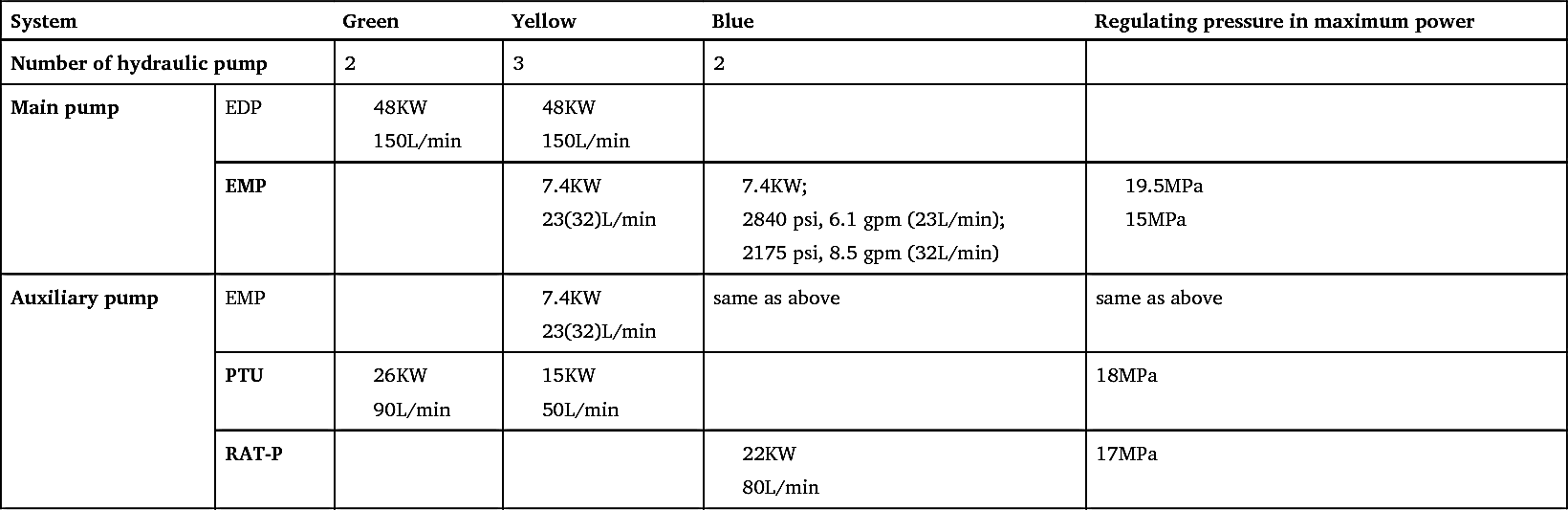
From A300 to A320, green and yellow two main hydraulic systems are independent to each other. Each uses a pressure-compensated engine-driven pump (EDP) to provide the main hydraulic source. In the meantime energy complementarity is achieved by a power-transfer unit (PTU). The yellow system is equipped with EMP to provide an auxiliary hydraulic source if the main hydraulic source fails, and equipped with a hand pump to provide hydraulic energy to control the opening and closing of the cargo door, when needed. The blue hydraulic system uses one EMP to provide standby hydraulic energy, and a ram air turbine (RAT) hydraulic pump is also equipped to provide standby hydraulic energy in an emergency where both engines have failed. The EDP of the green/yellow systems and EMP of the blue system provide hydraulic
energy for systems under normal working (no fault) conditions. The auxiliary pump will start if the main pump fails.
All three hydraulic systems – green, yellow and blue – have an engine, a gas pressure tank to provide air-entraining, and a booster accumulator. Two main hydraulic systems in the Ad320 use fire shut-off valves, which will cut the oil supply of the main hydraulic pump to ensure the safety of the system in an emergency.
Hydraulic devices use a new structure and new power allocation techniques to ensure enough supply of hydraulic energy and electric energy in emergencies such as engine failure (including all kinds of engine failure), engine disintegration (one engine), wheel rupture, lightning strike, fire, device external damage, accumulator break etc., to guarantee flying and landing. In addition, it can ensure that the basic functions and working safety of hydraulic systems will not be affected in conditions such as local rupture, local fire, thermal radiation (for example, in the engine area), flight critical value (maximum height, maximum acceleration etc.), environment change (temperature, ice, pollution, vibration), etc.
4.2.2. Main hydraulic system
Main hydraulic system refers to the green, yellow and blue systems. These three systems provide hydraulic power to aircraft user system. Each of these three hydraulic systems in the A320 uses its own gas pressure tank to increase the pressure of its own hydraulic pump. The aircraft’s left engine drives the hydraulic pump of the green system, and the right engine drives the hydraulic pump of the yellow system. When the engines are working, the hydraulic pumps of the green and yellow systems supply hydraulic energy. When only one engine works, the electric pump of the blue system automatically starts to provide standby hydraulic energy. The three system main pumps normally work at the same time. Hydraulic energy and main control components are arranged separately in three hydraulic cabins. The energy components of the green system are located in the main undercarriage; the energy components of the yellow system are located in the right ventral fairing; the energy components of the blue system are arranged in the left ventral fairing. Two hydraulic cabins (blue and yellow) are located in front of the main undercarriage cabin, respectively.
As shown in Fig. 4.1, the green system is pressure supplied by the left (No.1) EDP, the yellow system is pressure supplied by the right (No.2) EDP, the blue system is pressure supplied by an electric pump, and these
three main systems are automatically pressure supplied when the engines work. The two EDPs are connected to the corresponding engine by an accessory case. The electric pump of the blue system will start automatically when any one engine fails. The normal working pressure of all systems is 3000Psi.
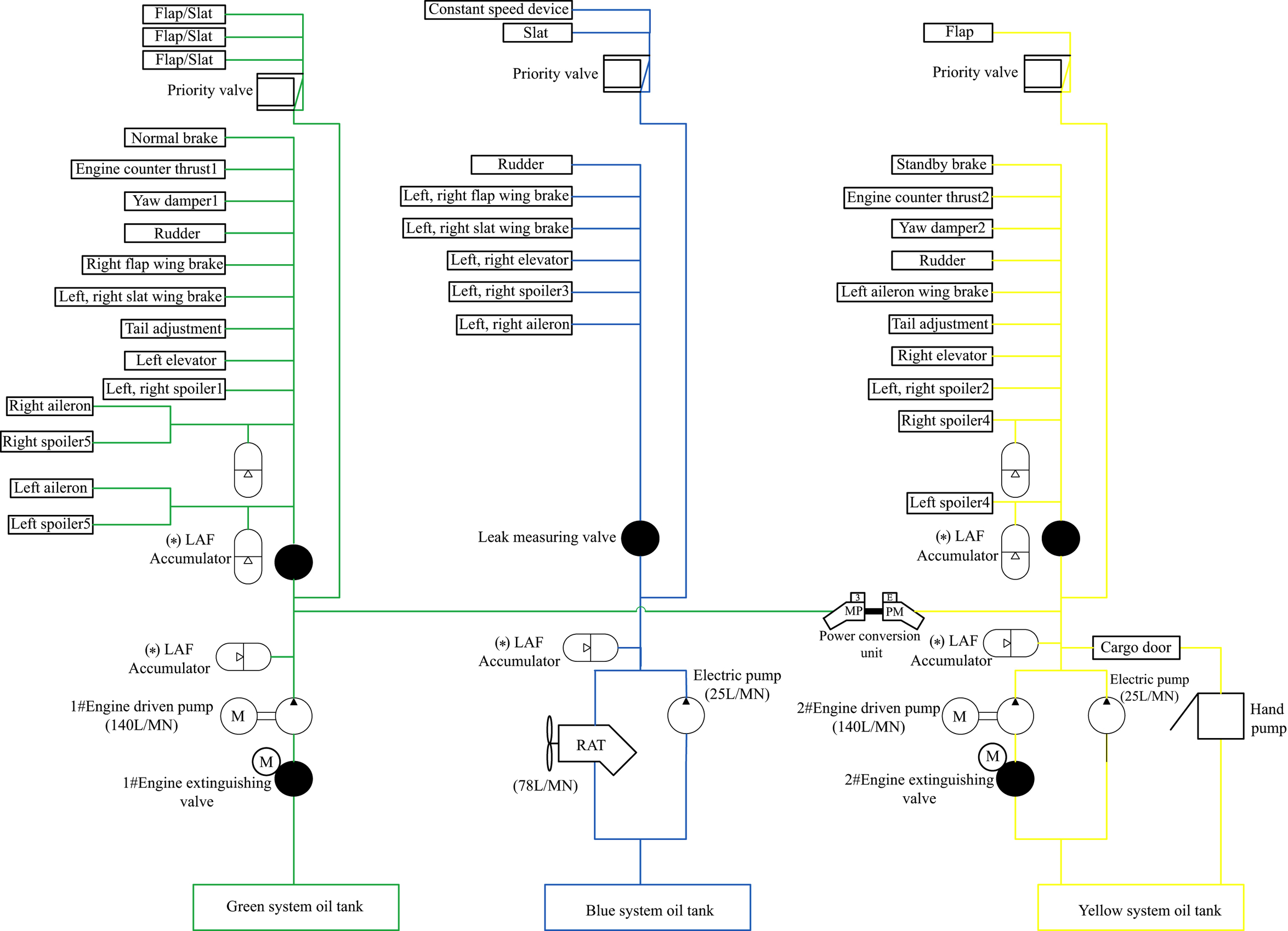
The green system mainly supplies hydraulic power to the undercarriage (including front wheel steering), normal brake, left (No.1) engine reverser, part of the flight control system, and the power conversion assembly, etc. Most components of the system are installed in the main undercarriage cabin, completely separated from the other two systems.
The yellow system mainly supplies hydraulic power to the cargo door, standby brake, right (No.2) engine reverser, part of the flight control system, and the power conversion assembly, etc. Most components of the yellow system are installed in yellow hydraulic cabin right to the ventral fairing in front of main wheel cabin. The yellow system works automatically with the start of the right (No.2) engine, can be operated in cockpit if necessary.
4.2.3. Auxiliary hydraulic system
The auxiliary hydraulic system supplies pressure for the aircraft when the main pump cannot supply pressure. The auxiliary hydraulic system and related components are the blue system RAT, PTU, electric pump to supply pressure for the yellow system, and a hand pump to supply pressure to cargo door only.
PTU of yellow system: PTU of green, yellow system is installed in main undercarriage cabin. There is no hydraulic connection between the green and yellow hydraulic systems. When the pressure difference between the green and yellow systems is 500Psi (3.44MPa), the two-way PTU of the power transform system operates automatically to achieve energy complementarity by transfering power between green system and yellow system. When the difference of pressure between green system and yellow system is over a set point, pressure is transferred to another system from the system with higher pressure, by PTU. The green and yellow systems open or close the PTU by using solenoid valves. In addition, a mechanical isolation joint is used to prevent the PTU functioning unexpectedly during service, which could be dangerous.
The RAT of the blue system is installed in the left ventral fairing cabin, in front of the main undercarriage cabin. RAT will be pop-up automatically if all failed. A turbine rotates under the action of airflow, driving a
hydraulic pump to supply hydraulic pressure, which drives CSM/G to supply emergency power to the aircraft. When both engines fail, one engine fails and the alternator of the other engine fails, or the power of the aircraft fails, the RAT can open automatically, but automatic function is only effective when the flying speed is higher than 100 knots. Flight and maintenance personnel can open the RAT manually from the cockpit. Once opened, it can only be closed on the ground.
The electric pump of the yellow system is installed in the hydraulic cabin of the right ventral fairing. When the engine or engine pump fails, the electric pump starts and supplies hydraulic energy to the yellow system. This electric pump supplies enough hydraulic power to the yellow system to drive all its components, and can supply pressure to the green system by PTU. When the cargo door is operated on the ground, hydraulic energy is supplied by the electric pump of the yellow system. A hand pump is equipped in the yellow system, which can supply hydraulic energy to control open and close the cargo door when there is no electrical energy.
4.2.4. Performance and characteristics of hydraulic system
I. Main performance index of A320 hydraulic system
The basic performance index of the A320 hydraulic system includes:
- 1. System pressure: 3000 Psi (20.6M Pa).
- 2. Hydraulic fluid: AS1241, Synthetic flame retardant hydraulic oil.
- 3. Working temperature of hydraulic oil: -54–107 °C. -55–60 °C for rated power; the largest temperature range is: -60–110 °C.
- 4. Environment temperature: In working area is -55–90°C; outside working area is -65–110 °C.
-
5. Oil filter accuracy: NAS1638 cleanliness grade 8. Filter element accuracy for high pressure is 15
 , for low pressure is 3μm.
 - 6. Total system volume:About 240 L.
- 7. Total mass of energy system: 410 kg (excluding hydraulic oil and fixed device); of this, components about 193 kg.
- 8. Components of energy system: About 110 kinds, 253 hydraulic components.
- 9. Measured maximum flight height of device: 13 716 m.
- 10. Working life: 20 years.
Aircraft hydraulic system reduces quality only on the premise of high reliability; the failure probability of hydraulic system devices is 1/109 flight hours, which is more than the design life; apart from pump and motor, all components’ design life are the same as aircraft working time of about
20 years or 60 000 working hours. The power allocation of the A320’s hydraulic system is shown in Table 4.2. The energy requirement of the main flight control system is the largest. The maintenance of the aircraft, including functional testing of the whole aircraft, uses the devices on the aircraft to supply hydraulic energy. Hydraulic energy and electric power on the ground are used to do aircraft power testing.
II. Display and alarm system of hydraulic system
A central electronic system in the A320’s cockpit inspects and monitors the hydraulic energy and executive system. The start of engine, auto start of hydraulic pump and state parameters of the hydraulic energy system are inspected via a control panel. The control panel also displays the system’s failure status, and the pilot can cut off the hydraulic system via the control panel in the event of critical failure. All system failures are handled in parallel by the electronic ‘aircraft surveillance system’, and displayed simultaneously on ECAM. A range of sensors are installed in the three hydraulic systems of the A320, and are used to monitor the amount of oil in the tank, system pressure, output pressure of the pump, temperature of hydraulic oil, the pressure in the oil tank, etc. These data are used in system alarm indication, operation, and maintenance. Alarms include audio alarm, light alarm and display alarm information by ECAM.
When a fault appears, flight safety units auto call the corresponding system display condition according to the priority level predetermined. n addition, pilots can display interface of any system. As the reference for pilots to control aircraft and system when fault appears, screen will display the operation instruction of pilots. Faults during a flight will be recorded, in order that corresponding measures can be applied during ground maintenance to remove faults according to that record.
III. Mass of A320 hydraulic system
The total mass and distribution of the A320 hydraulic system are important factors affecting aircraft mass and distribution. Insuring effectiveness and safety, all kinds of new materials and new hydraulic technologies (such as increasing system working pressure) are used to reduce the mass of the hydraulic energy system, improving the economic efficiency of aircraft oil effectively. The A320 aircraft in the precondition that ensuring aircraft hydraulic energy systems backup each other, achieves unified of aircraft hydraulic control characteristics and maximum oil economic efficiency.
Table 4.2
IV. Reliability and maintainability of hydraulic system
Reliability and maintainability are an import performance index of an aircraft, having important effects on the safe use and life cycle cost of the aircraft. With the modernization of the manufacturing process for large aircraft, reliability and maintainability indices have been included in the program at the design stage; it has been fully demonstrated by researchers that this ensures a significant reduction in maintenance support costs while the aircraft is in use, which greatly reduces the life cycle cost of the aircraft.
High reliability means a low fault rate. The reliability index set for the A320 is 99% in the two years after entering service; this means the fault rate must be no greater than 1%. For this purpose, designers decomposed the overall 1% fault rate into the A320’s various systems, thus determining the fault rate range of the hydraulic system. According to calculation, the failure probability of whole hydraulic device is 1/ (109 flight hours), more than the aircraft life time. The working life of the aircraft is about 20 years, about 60 000 working hours, or approximately 48 000 flight hours. Apart from pump and motor, all components are designed according to this life time.
Good maintainability mainly means the time efficiency of troubleshooting and maintenance on the ground during the using process; specifically, it includes the replacement time of the main system hydraulic components, replacement time of standby system hydraulic components, replacement time of auxiliary system hydraulic components and hydraulic related accessories, etc. High reliability and good maintainability exist side by side and play a part together. Maintainability of large aircraft hydraulic systems mainly means maintenance of the aircraft hydraulic system on the ground and inspection device.
For maintenance of the aircraft’s hydraulic system (including actuating mechanism) on the ground and inspection (engine driven pump off work) the A320 is equipped with the following devices:
- 1. Pressure supply connecting joint outside aircraft. Pressure pipeline and oil return line of three systems all installed self-seal connecting joint.
- 2. System maintenance and debug can be performed on the ground without starting the engines using power from the electric pump of the yellow or blue system and application of the PTU.
- 3. Quick release joint and check valve ensure the quick replacement of pump without leakage of hydraulic fluid.
- 4. For the convenience of system detection and adjustment, control panel is placed at the place easy to approach, and main maintenance devices are collected on the ‘maintenance panel’.
- 5. Oil filling connecting joint outside aircraft, supplying tank.
- 6. The aircraft is equipped with an oil system filling hand pump and selector valve with oil tank condition monitoring, making system maintenance easy to achieve.
- 7. Each accumulator has a nitrogen charging valve and a gauge for pressure monitoring installed.
- 8. The oil filter has an oil pollution indicator installed. The replacement of polluted oil filters can be handled without tools or loss of hydraulic fluid.
- 9. A hydraulic oil sampling valve is installed to each system.
- 10. With the help of a switch valve and an outside-aircraft measurement device, internal leaks of each actuating mechanism (especially servo control system) can be checked.
- 11. System has auto exhaust function under normal working conditions, and a liquid separator in the pipeline of the oil tank pressure increasing system; this gives the system a relatively high degree of pollution control.
- 12. A manual control oil tank pressure relief valve is installed to each system.
- 13. The structure of all kinds of connection and components ensure confusion during installation and replacement.
- 14. RTA functional testing and calling back are carried out by a device installed on the maintenance panel.
- 15. Components are installed on split seats to reduce the workload of replacement in necessary positions.
- 16. When using standard tools to install components, it is not necessary to remove the adjacent element.
- 17. Cargo door can be opened or closed by hand pump or by the electric pump of the yellow system.
The A320 aircraft hydraulic system uses main hydraulic system, auxiliary hydraulic system and standby hydraulic system, and RAT and PTU when there is a single engine fault, to ensure the requirement of one fault safety and two fault reliability of aircraft hydraulic system. It is seen that the A320’s hydraulic system allocation is reasonable, the system is concise, and it has a certain degree of advancement. Even nowadays, civil airborne hydraulic systems having developed further, the A320’s hydraulic system still has important reference value for developing civil aircraft similar to the A320 series.
4.3. Thermal analysis of aircraft hydraulic systems and oil temperature control technology
4.3.1. Fundamental theory of thermal analysis of hydraulic systems
Aircraft hydraulic systems are used to meet the requirements of all kinds of flight control. It is a transmission process of mechanical energy to hydraulic energy to mechanical energy, from the point of view of energy transmission and transformation. The pressure, speed and direction of fluid is controlled according to requirements during operation. Energy loss during the procedure of energy transmission and transformation is inevitable. The lost energy finally transforms to heat, increasing the temperature of the hydraulic fluid. In the meantime, there is heat exchange between the hydraulic system and the outside environment. Therefore, thermal analysis of aircraft hydraulic systems and temperature control problems involve correlation theories in hydraulic drive, heat transfer and thermal dynamics, including:
- • Partial correlation theories in hydraulic drive, including flow continuity equations, force equilibrium equations for moving parts and calculations of all kinds of loss, etc.;
- • Partial correlation theories in heat transfer, including correlation theories of heat conduction, convection, radiation and complex heat transfer equations in engineering applications; and
- • Partial correlation theories in thermal dynamics including energy equations (the first law of thermodynamics) and Carnot cyclic expression (the second law of thermodynamics).
Reasonable allocation of pipeline, oil tank and the oil return process of the hydraulic system can achieve effective control of oil temperature. Fig. 4.2 shows the load distribution of an aircraft hydraulic system.
4.3.2. Static thermal analysis modeling and temperature calculation method of aircraft hydraulic systems
I. Static thermal analysis modeling of aircraft hydraulic systems
Mechanical loss and volume efficiency loss of aircraft hydraulic systems form the total energy loss. The energy transformation to heat energy increases the temperature of oil and components.
Heating power P1 (kW) produced by hydraulic pump
Heating power P
2 (kW) by orifice of through valve
where:
The system loses pressure energy when oil flows through the pipeline and valve mouth; the lost pressure energy being used to overcome frictional force between oil and pipe wall, and frictional force between steams. This causes the oil temperature to increase.
Normally, because the area of dissipation of the pipeline is small and the flow time in the pipeline is not long enough, it is considered that heat loss due to power loss is very small and can be neglected in the static calculation method.
Oil flowing in the pipeline can cause pressure loss along the pipeline and also partial pressure loss. Partial pressure loss of the system is ignored and only pressure loss along the pipeline is considered in the static heat calculation. According to experience, the loss of the pipeline is about 0.03∼0.05 of total energy loss, that is,
where:
Heating power P
4 of hydraulic actuating element
When only considering the heating power of the hydraulic cylinder in normal circumstances, there is,
Where,
Total heating power P of system
The total heating power P is the summation of heating power from all the above parts, that is,
The average heating power of the system in an action loop can be calculated by,
The calculation of the static heating power of the hydraulic system does not consider the change in physical characteristics of the oil due to the temperature increasing, such as heat transfer coefficient
 , density
 , thermal conductivity
 , specific heat at constant pressure
 , etc. In addition, the temperature characteristics of the pipeline and element material of the hydraulic system can also change. The change of these above parameters can directly affect the nodal pressure of the hydraulic system and the flow allocation of branches, and so change the dissipating and endothermic heat conditions of the system.
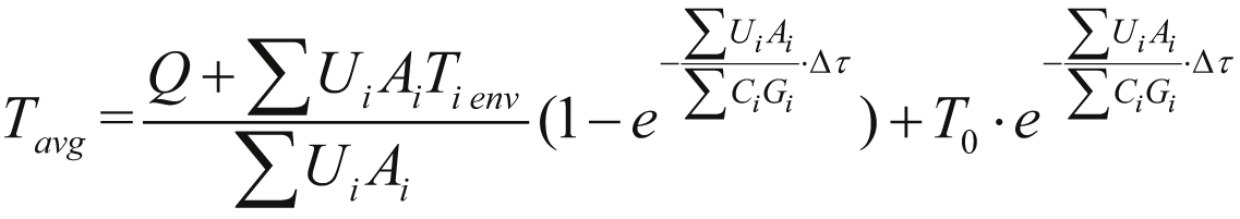
II. Static temperature calculation method of aircraft hydraulic systems
The static temperature calculation method of aircraft hydraulic system is to do the calculation of the oil tank temperature of the system under static working station using the so-called average oil temperature calculation method. The average oil temperature calculation method involves considering factors such as self-heating of the hydraulic system, effects of environmental temperature, dissipation of heat from radiators, etc. When self-heating of the system is equal to dissipation of heat, it is believed that the oil in a hydraulic system, providing it has a large enough volume to provide the required heating capacity (normally this is an oil tank), can reach a state of thermal balance, and the oil temperature will not change again. In thermal balance, the temperature of oil is the average temperature of system oil under this condition. Assuming the following conditions are satisfied in the system:
- 1. The temperature of catheters and accessories is the same as the oil temperature inside components, and is assumed to be equal to T avg.
- 2. Separating the system into several zones according to environmental temperature, the heat capacity of each zone is C i G i , the local total heat transfer coefficient of this zone is U i .
-
3. The total heat capacity of the system is
 (hereinafter referred to as (
 ),the local total heat transfer coefficient of this zone is U
i
, local environment temperature
),the local total heat transfer coefficient of this zone is U
i
, local environment temperature
 , oil pump heat generation rate
 and heat dissipation rate
 will not change with time in the infinitesimal time

According to the first law of thermodynamics, for the hydraulic system there is,
In the meantime, according to heat transfer theory there is,
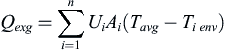
where
 ,
,
 and
are the heat transfer coefficient, heat transfer area and environment temperature of the ith zone, respectively.
and
are the heat transfer coefficient, heat transfer area and environment temperature of the ith zone, respectively.
Assuming,
From the above equations, it can be obtained,
Assuming that, when time
 , the average oil temperature is
 ;
;
 , then the average system temperature T
avg
after the infinitesimal time
, then the average system temperature T
avg
after the infinitesimal time
 is,
is,
 (4.8)
(4.8)
4.3.3. Dynamic thermal analysis modeling and temperature calculation method of aircraft hydraulic systems
I. Dynamic thermal analysis modeling of aircraft hydraulic systems
The theoretical basis of dynamic thermal analysis modeling of aircraft hydraulic systems is the first law of thermodynamics. According to the first law of thermodynamics, everything in nature has energy. Energy cannot be created, cannot be eliminated, and can only be transferred from one type to another type under certain conditions. The total amount of energy is constant during the transfer process.
The energy transfer in thermodynamics occurs between the thermodynamic system and the environment. During the transfer process, the thermodynamic system can obtain a part of its energy from the environment, and can also output a part of its energy to the environment. According to the energy conservation principle, the amount of decrease of
energy in the environment must be equal to the amount of increase of energy in the thermodynamic system. For a thermodynamic system, there is,
There are only three ways to exchange energy between a thermodynamic system and the environment by interaction:
Therefore, Eq. (4.9) can also be written as,
where
 is the increasing energy of the thermodynamic system.
This is the expression of the first law of thermodynamics. The sign in this equation is set as: when
 ,
,
 , it is a positive sign to indicate the thermodynamic system absorbing heat; when
 ,
,
 ,it is a positive sign to indicate the thermodynamic system outputting work, and vice versa.
II. Dynamic temperature calculation method of aircraft hydraulic systems
When the dynamic temperature of an aircraft hydraulic system is calculated, fluid flow in the system is considered as one-dimensional unsteady flow. The energy equation of one-dimensional unsteady flow, established according to the first law of thermodynamics, is the theoretical basis of dynamic temperature calculation of aircraft hydraulic systems.
For one-dimensional unsteady flow, a control volume is chosen (Fig. 4.3). Ignoring the kinetic energy and potential energy change inside the control volume, according to the first law of thermodynamics, the energy equation of the control volume can be written as,
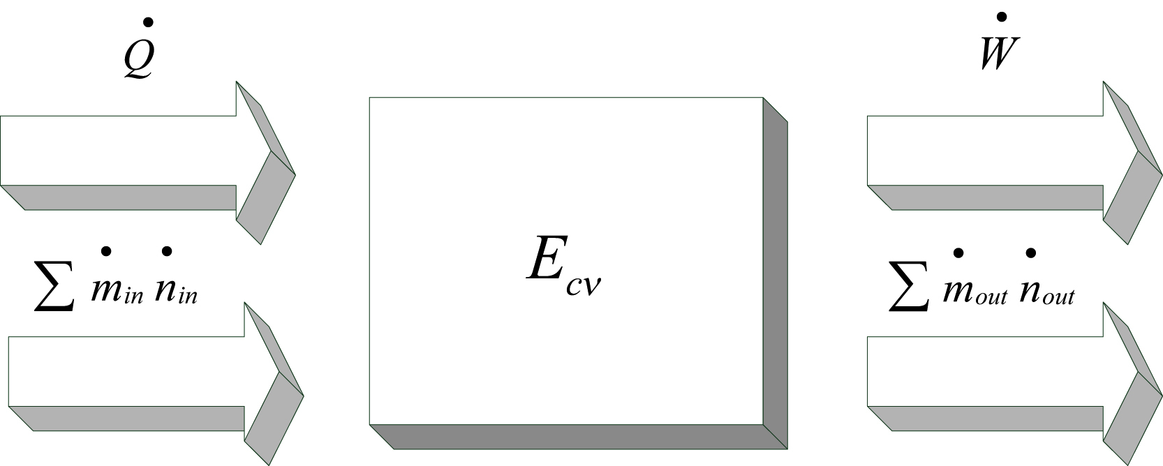
Here, subscript ‘out’ and ‘in’ indicate input and output of control volume, respectively.
Assuming the property of hydraulic oil in the control volume is homogeneous, and heat from throttling all gets into the hydraulic oil, ignoring the kinetic energy and potential energy change of the hydraulic oil, the energy inside the control volume can be expressed as,
Where,
Finding the derivation of time of the above equation, there is,
According to the definition of specific enthalpy, it is known,
Where,
The differential form of specific enthalpy is,
Where,
Where,
Among it, W normally consists of two parts – shaft work and boundary work – its differential form is,
Substituting Eq. (4.18) into Eq. (4.17), after simplifying and transposing there is,
Where,
The density of oil changes with the changing of pressure and temperature, that is,
From Eq. (4.20), there is,
For the change of density of oil inside the control volume, there is,
 (4.22)
Substituting Eqs. (4.21) and (4.22) into Eq. (4.19), the expression of the change of oil temperature in the cavity can be obtained, which is the expression of the dynamic temperature of the aircraft hydraulic system,
III. Calculation example of dynamic temperature of aircraft hydraulic systems
The design procedure of one type of aircraft hydraulic system is taken as an example to illustrate the procedure of dynamic temperature calculation. First the flight process of the aircraft, the flight time of each stage and hydraulic load, should be determined, and a basic thermodynamic equation formulated. The main users of this kind of aircraft hydraulic energy system include the following:
- 1. Primary flight control system: elevator, rudder, aileron etc.
- 2. Secondary flight control system: flight spoiler and ground spoiler, slat, flap etc.
- 3. Undercarriage control system: retracting and dropping of undercarriage, nose-wheel steering etc.
- 4. Brake system: main brake, standby brake.
- 5. Thrust reverser: left and right engine reverser.
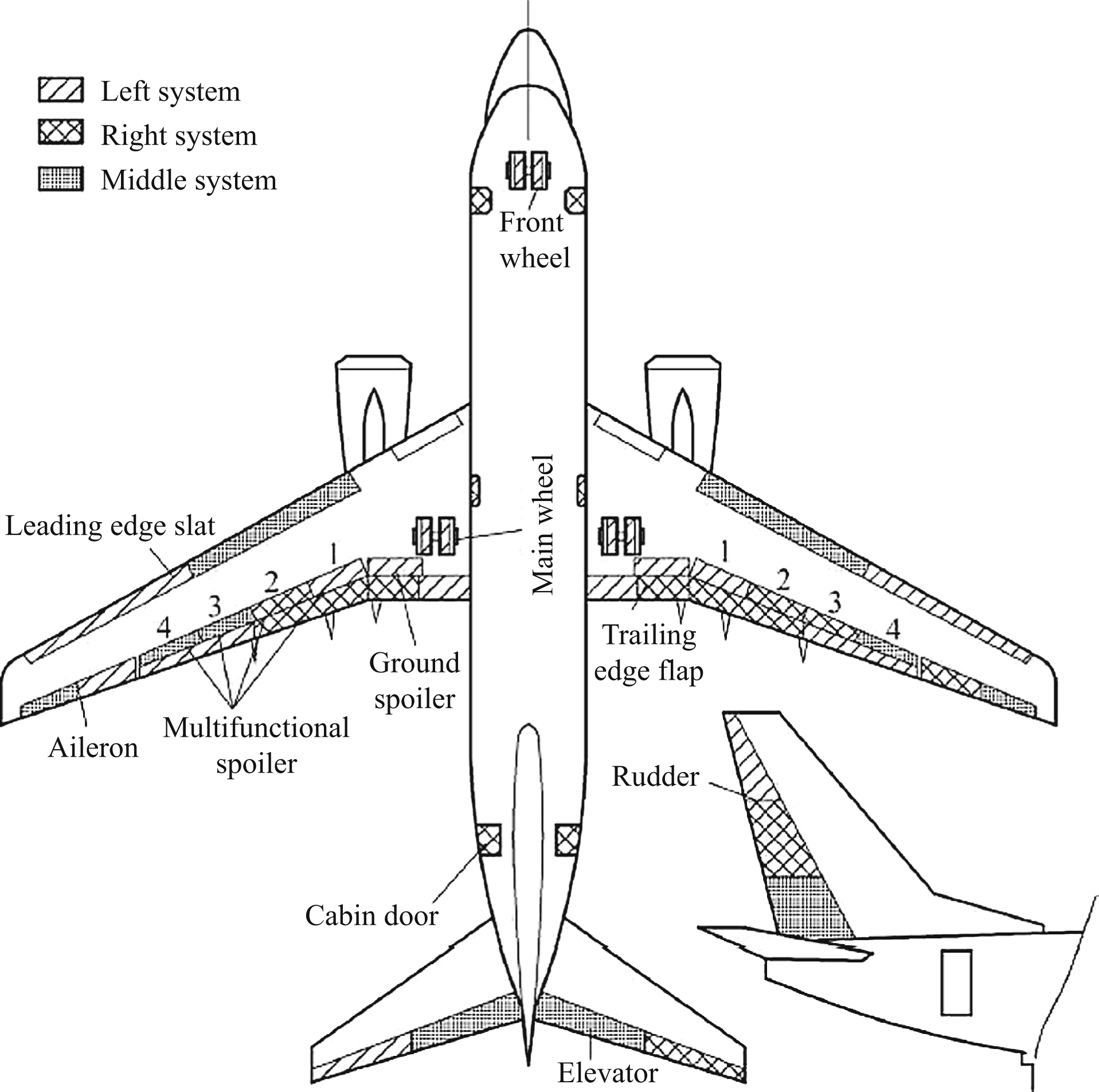
This type of aircraft hydraulic system has three independent systems: left, middle, and right. Among them, the main users of the left system are the left elevator, rudder, left aileron, flap, slat, multi-function spoiler, ground spoiler, undercarriage system, main brake, and left engine reverser
etc.; main users of the right system are the right elevator, rudder, right aileron, flap, multi-function spoiler, cabin door, standby brake, and right engine reverser etc.; main users of the middle system are the elevator, rudder, aileron, slat, multi-function spoiler etc. Table 4.3 shows the hydraulic user configuration of each system.
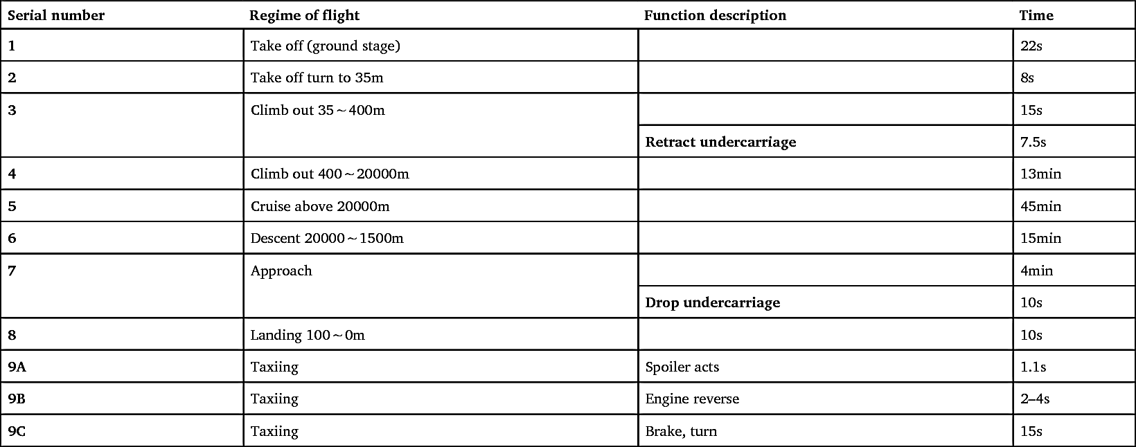
Load power allocation of left, middle and right systems of this type of aircraft’s hydraulic energy is shown in Fig. 4.4. The regime of flight is separated into 9 stages, as shown in Table 4.4.
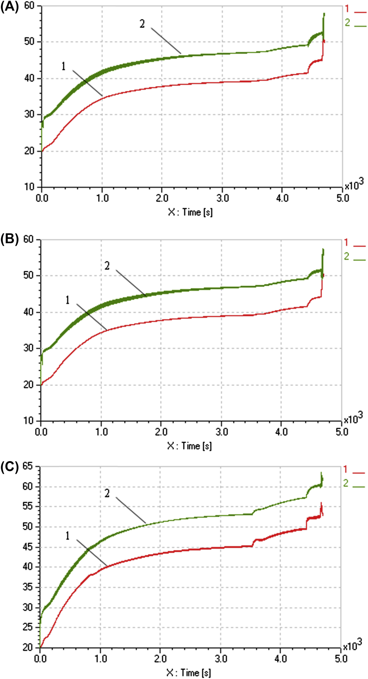
The right system is taken as an example for a dynamic temperature calculation. The environment and original temperature is set to be 20°C. According to the flight profile to do the full profile calculation (time 4700s), the curves of dynamic temperature distribution and change of each part of the hydraulic system are obtained as follows.
I. Temperature at pump
Fig. 4.5 shows the dynamic temperature change curve of the right system pump. It is seen that at the first four flight profiles the system load flow is relatively large; heat generated by the hydraulic system load is larger than the heat dissipated by the system pipeline; the temperature of return oil in the hydraulic user pipeline is higher than the temperature of oil in the tank.
When the aircraft is at the cruising stage, the system load flow is relatively small; the heat generating efficiency of system hydraulic user decreases; but due to the effect of housing return oil, the temperature of the pump is still on the rise. When the aircraft is in the descent stage, flap and other components start to act; the system load flow increases, which has a substantial effect on the change of system temperature. When the aircraft is in
the landing stage, the engine reverser and dive flap start to work; low temperature oil getting into the system leads to the relatively large decrease in return oil temperature in the system. But the total heat generating power of the system is still larger than the heat dissipating power, the temperature of return oil in the hydraulic user pipeline increases rapidly due to the effect of oil temperature at the pump.
Table 4.3
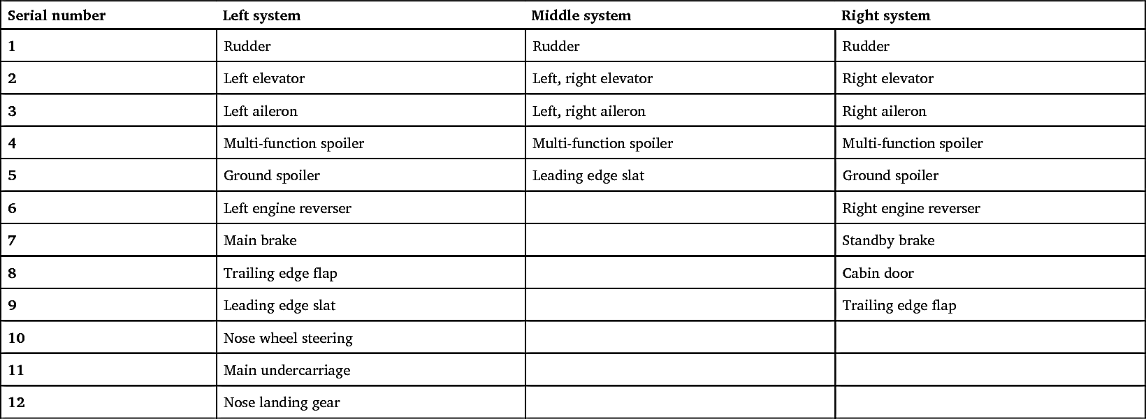

Table 4.4

II. Temperature at hydraulic users
Fig. 4.6 shows the dynamic temperature change curve of all users of right hydraulic system. The rudder, elevator, aileron and multi-function spoiler
work at every stage of the system. The temperature in the locations these components are installed is lower than the temperature of oil at the pump outlet, due to the dissipating effect of the pipeline. Because the load flow and power are different at different stages, the speed of temperature change varies. Because each load is located in a different part of the aircraft, the lengths of the pipelines transferring the hydraulic oil are different; the consequent difference in heat dissipation leads to the big temperature difference of each load. Using the temperature at hydraulic user outlet for comparison at 3000s (cruise stage), the highest temperature is at the multi-function spoiler, about 55°C; the second highest temperature is at the aileron, about 53°C; the lowest temperature is at the rudder and the elevator, about 48°C.

4.4. Conclusions
Taking the hydraulic system of the Airbus A320 as an example, combining the structure and function of civil aircraft hydraulic energy systems, redundancy design is commonly used in modern mainstream models of aircraft – that is, three independent hydraulic energy systems are installed, equipped with energy PTU and various emergency energy sources. Meanwhile, with the aim of developing features to match the requirements of modern aircraft lightweight hydraulic systems, a thermal analysis technique of aircraft electrohydraulic servo control systems based on temperature control is used, including static temperature analysis modeling, dynamic temperature analysis modeling and calculation examples; this can control the heating of return oil at hydraulic pump housing with reasonable success.
Effectivly taking advantage of the special conditions in large passenger aircraft of long distances between the hydraulic energy source and hydraulic energy user, and the distinguishing feature of the complex configuration of hydraulic system pipelines, making the best of the environment heat dissipating method and allocating radiators sensibly, is the key to civil aircraft hydraulic system temperature active control technique. Aircraft oil temperature active control methods include:
- 1. Natural heat dissipation method, which is the heat dissipation of aircraft hydraulic system, mainly from the system pipeline, to reach a balance of hydraulic system temperature. The pressure supply pipe from energy system to actuating mechanism and the return pipe of actuating mechanism have enough dissipation area to achieve the required dissipation; there is no extra radiator in this method.
- 2. Fuel radiator temperature control method, which is to control hydraulic system temperature using a radiator. Normally, the radiator is installed inside the aircraft fuel tank to improve the dissipation effect.
- 3. Pipeline dissipation temperature control method, which is to dissipate heat by the system pipeline, and by changing the configuration of the hydraulic system pipeline, such as lengthening the pipe installed inside the aircraft fuel tank.
There is a potential risk using natural heat dissipation method in the system.The radiator dissipation method and pipeline dissipation method are very effective in controlling the system temperature. When the pipeline dissipation method is used, a housing return oil pipeline dissipation method is a bit better than a total return oil pipeline dissipation method.
..................Content has been hidden....................
You can't read the all page of ebook, please click here login for view all page.