
Chapter 7
Pressure Characteristics of Symmetrical Uneven Underlap Hydraulic Slide Valves
The sixth chapter analyzed the runaway of the symmetrical hydraulic valve controlled asymmetrical hydraulic cylinder servo system, cavitation and the sudden change of the reversing pressure of the hydraulic cylinder. A new asymmetric hydraulic valve controlled asymmetric hydraulic cylinder was proposed to realize the flow matching and system coordination between the hydraulic components. On this basis, the pressure characteristics of symmetrical uneven underlap cylindrical sliding valve were analyzed.
The working characteristics of the hydraulic servo valve depend on the throttling working side of the valve core and the valve sleeve and the manufacturing accuracy of the overlapping amount of the core and the sleeve. The width of spool shoulder of the underlap slide valve is narrower than the width of the groove on the valve sleeve. When the four throttling edges have unequal openings, they are called underlap valves with unequal overlapping amount. This chapter analyzes the pressure characteristics, pressure gain characteristics and zero leakage of the symmetrical uneven hydraulic servo valve, and introduces application examples.
7.1. Pressure characteristics of symmetrical uneven hydraulic slide valves
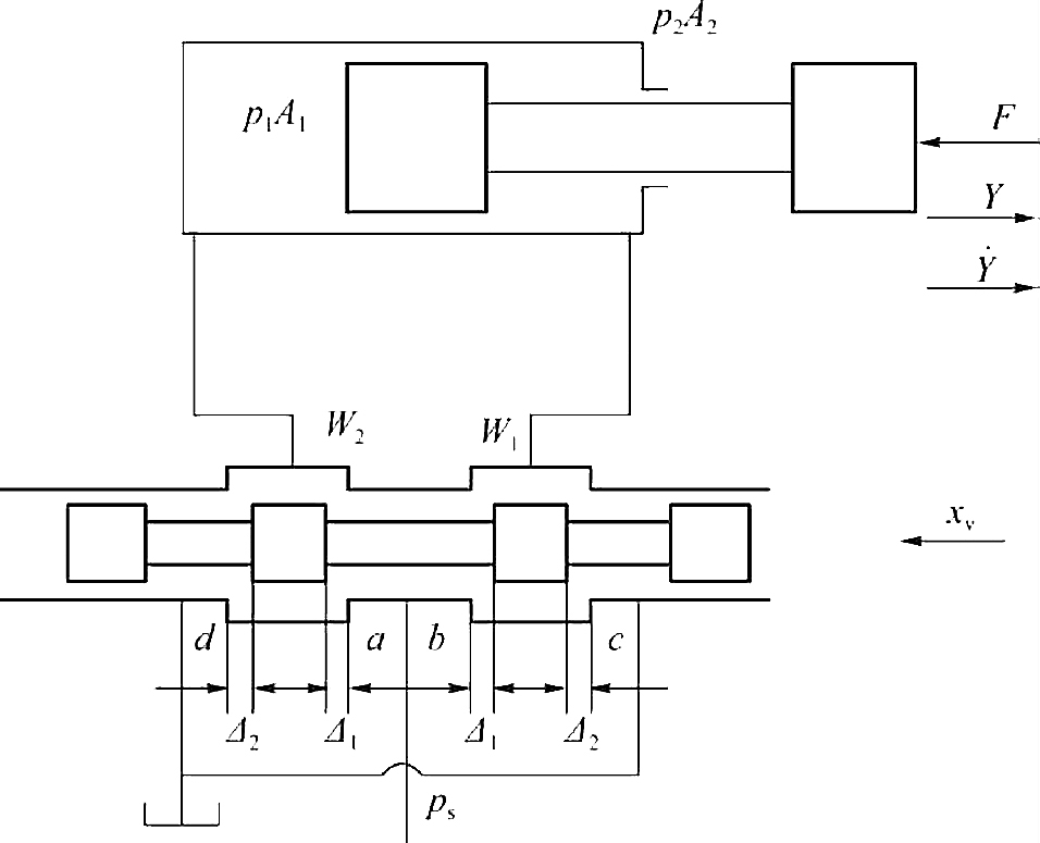
The valve control hydraulic cylinder power mechanism diagram is shown in Fig. 7.1. Set the slide valve as underlap and four throttling edges symmetrically, symmetrical superposition amounts of Δ1 and Δ2, respectively, and Δ1≠Δ2, valve working stroke in the underlap range, that is
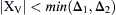 . When the fluid flows through the four throttling edges, they are turbulent flows, and ignore the internal leakage of the hydraulic cylinder and hydraulic valve. In steady state operation,
 , the piston position of the hydraulic cylinder is stationary, and the oil
volume in and out of the hydraulic cylinder is zero (Q
L = 0), that is Q
a = Q
d, Q
b = Q
c. The relationship between the two chamber pressures p
1 and p
2, the load pressure p
L and the displacement of the slide valve x
v is analyzed, that is the pressure characteristic p
L = f(x
v) at Q
L = 0, and the characteristic curve of the system working pressure is obtained.
, the piston position of the hydraulic cylinder is stationary, and the oil
volume in and out of the hydraulic cylinder is zero (Q
L = 0), that is Q
a = Q
d, Q
b = Q
c. The relationship between the two chamber pressures p
1 and p
2, the load pressure p
L and the displacement of the slide valve x
v is analyzed, that is the pressure characteristic p
L = f(x
v) at Q
L = 0, and the characteristic curve of the system working pressure is obtained.
Suppose that the orifice area of the hydraulic valve matches the flow of the hydraulic cylinder, there is,
Where,
And assuming,
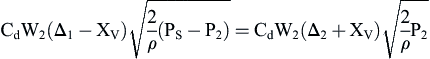
When the piston of the hydraulic cylinder is stationary, the flow equation of the hydraulic valve satisfies:
 (7.2)
(7.2)
 (7.3)
(7.3)
Where,
The load force equilibrium equation of the hydraulic cylinder piston is,
Load pressure is defined as,
The dimensionless quantity of valve displacement is
 , and the dimensionless quantities of the pressure and load pressure of the two chambers are


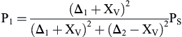
 , respectively. The uneven coefficient of the axial dimension opening of the cylindrical spool valve is defined as m =Δ2/Δ1. From Eqs. (7.2) and (7.3), when the displacement of the valve is x
v, the pressures of the two chambers of the hydraulic cylinder are respectively,
, respectively. The uneven coefficient of the axial dimension opening of the cylindrical spool valve is defined as m =Δ2/Δ1. From Eqs. (7.2) and (7.3), when the displacement of the valve is x
v, the pressures of the two chambers of the hydraulic cylinder are respectively,
 (7.5)
(7.5)
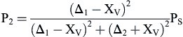 (7.6)
(7.6)
When Eqs. (7.5) and (7.6) are dimensionless, the working pressure of the two control chambers of the hydraulic cylinder can be obtained respectively,
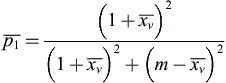 (7.7)
(7.7)
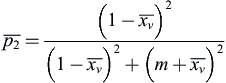 (7.8)
(7.8)
Eqs. (7.7) and (7.8) are added, and the expression of the sum of the pressure of the two chambers of the hydraulic cylinder can also be obtained,
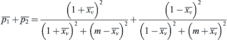 (7.9)
(7.9)
Eqs. (7.5) and (7.6) are substituted into the load pressure expression p
L, and dimensionless, the load pressure characteristic is obtained as follows,
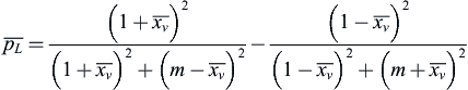 (7.10)
Eqs. (7.7) and (7.8) indicate that the working pressure
 of two the control chambers of the hydraulic cylinder is nonlinear, with the valve displacement
 , and the pressure characteristic curve of the two chambers is symmetrical to
 , and is also related to the uneven coefficient m of the valve opening. From Eqs. (7.7) and (7.8), we can obtain the dimensionless working pressure characteristic curve at different uneven coefficients of the positive opening m, and the pressure distribution when the valve displacement reaches the saturation state of
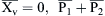
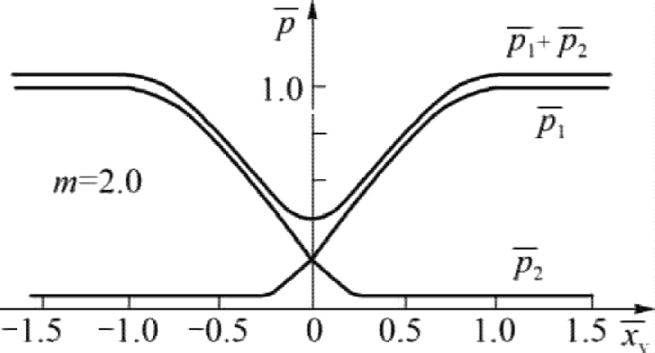
 . Fig. 7.2 shows the dimensionless characteristics of the two chambers’ pressure of the underlap valve controlled hydraulic cylinder at Δ2 = 2Δ1 i.e. m = 0.5. Fig. 7.3 shows the dimensionless characteristics of the two chambers’ pressure of the underlap valve controlled hydraulic cylinder at Δ2 = Δ1 i.e. m = 1. Fig. 7.4 shows the dimensionless characteristics of the two chambers’ pressure of the underlap valve controlled hydraulic cylinder at Δ2 = 0.5Δ1 i.e. m = 2.
Eq. (7.9) shows that
 is constant if and only if the axial dimensions of the cylindrical slide valve are symmetrical and equal, i.e. m = 1; when the axial dimensions of the cylindrical slide valve are
symmetrical and unequal, that is, m<1 or m>1,
is constant if and only if the axial dimensions of the cylindrical slide valve are symmetrical and equal, i.e. m = 1; when the axial dimensions of the cylindrical slide valve are
symmetrical and unequal, that is, m<1 or m>1,
 is the function of
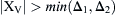
and is nonlinear. At null position
is the function of
and is nonlinear. At null position
 , has the maximum or minimum 2/(1+m2). As illustrated in Figs. 7.2 to 7.4, there are:

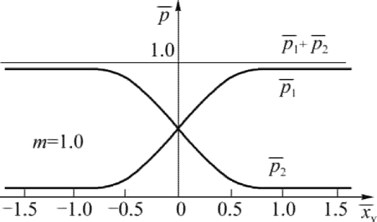
- 1. The curve of the pressures of the two load channels of the hydraulic valve varies with the nonlinear displacement of the valve, and is symmetrical to the ordinate axis.
-
2. For a hydraulic slide valve with symmetrical and equal opening amounts, in a larger range near the null position, the linearity of the pressure characteristic curve is relatively good, and its sensitivity is the highest; for a hydraulic slide valve with symmetrical unequal openings, in the smaller area near the null position, that is, within
 range, the pressure characteristic curve has good linearity and sensitivity. When designing hydraulic valves, the displacement of the valve is limited so that it moves within the positive opening range, i.e. (
.
range, the pressure characteristic curve has good linearity and sensitivity. When designing hydraulic valves, the displacement of the valve is limited so that it moves within the positive opening range, i.e. (
. -
3. For a hydraulic slide valve with a symmetrical equal opening quantity, the sum of pressures of the two load chambers is equal to the supply pressure, that is, when m=1,
 is constant, and when in
,
is constant, and when in
,
 , this kind of hydraulic system with a symmetrical equal opening spool valve is very convenient for analysis; when m = 0.5,
 , and at
 ,
,
 ; when m = 0.707,
 ; when m = 2,
 , and at
,
, and at
,
 . It can be seen that the pressure of the two load passages is not 0.5p
s when the slide valve with symmetrical unequal positive opening is in null position. Near null position,
is not a constant, but a function of valve displacement
. The dynamic analysis of the hydraulic system composed of such valves is difficult and can be simulated by computer.
. It can be seen that the pressure of the two load passages is not 0.5p
s when the slide valve with symmetrical unequal positive opening is in null position. Near null position,
is not a constant, but a function of valve displacement
. The dynamic analysis of the hydraulic system composed of such valves is difficult and can be simulated by computer.
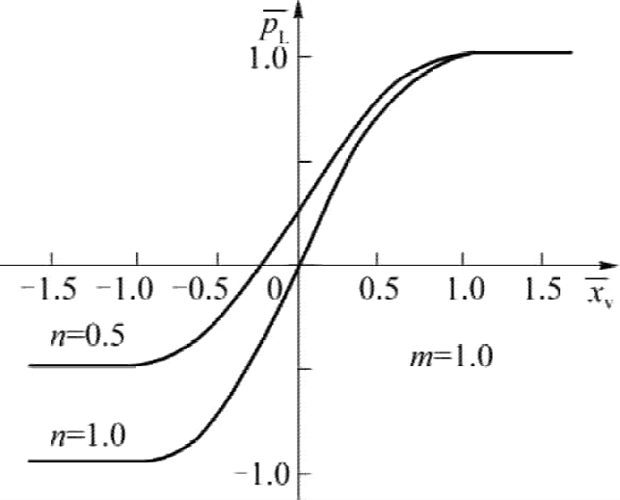
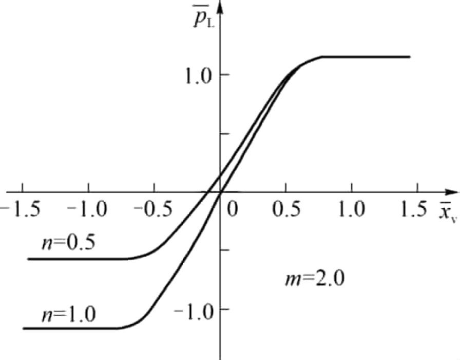
By Eq. (7.10), the dimensionless load pressure – valve displacement characteristic curve can be drawn at different values of m and n, as shown in Figs. 7.5 to 7.7.

-
1. Symmetrical hydraulic valve controlled symmetrical hydraulic cylinder system (n = 1), when no-load
 , the valve is in null position
; when the load is
, the valve is in null position
; when the load is
 , the steady state of the valve will deviate from the null position
.
, the steady state of the valve will deviate from the null position
. -
2. Asymmetric hydraulic valve controlled asymmetric hydraulic cylinder system (n = 0.5), when no-load
, the valve can make the steady state of the work point in null position
. As shown in Fig. 7.6, m = 1,
 , that is when F = 0.25p
s
A
1, the steady operating point of the valve is at null position.
, that is when F = 0.25p
s
A
1, the steady operating point of the valve is at null position.
7.2. Pressure and leakage at null position
7.2.1. Pressure at null position
When the slide valve is in the neutral position, that is null position, the null position pressure value and null position load pressure value of the slide valve can be obtained by Eqs. (7.7), (7.8) and (7.10).
At null position, the load pressure is,
From the above equation, the null position pressure value is related to positive openings symmetrical unequal coefficients m of the spool valve. A cylindrical slide valve with symmetrical and equal opening quantity (m = 1), the null position pressure is 50% of the oil supply pressure, i.e.
 . A cylindrical spool valve with symmetrical unequal openings, such as m < 1, has a null position pressure greater than 50% of the supply pressure, i.e.
 ; when m = 0.707,
; When m>1, the null position pressure is less than 50% of the oil supply pressure, i.e.
; when m = 0.707,
; When m>1, the null position pressure is less than 50% of the oil supply pressure, i.e.
 .
.
Eq. (7.12) reflects the load pressure on the hydraulic system when the hydraulic valve is in the null position. According to this formula, the hydraulic system is designed properly so that the zero speed balance point of the hydraulic system is in the null position of the valve.
7.2.2. Leakage at null position
Leakage at null position is,
Substituting Eqs. (7.2), (7.3) and (7.11) into Eq. (7.13), the leakage at null position can be obtained as,
 (7.14)
Eq. (7.14) shows that the null position leakage of the hydraulic valve is directly related to the symmetrical unequal coefficient m of the valve opening, and the asymmetry coefficient n of the valve flow window. When the valve parameters Δ1, W
1, n, p
s are constant, the coefficient
 reflects the magnitude of the leakage at null position. In order to reduce the null position leakage, reduce the oil supply and the power loss of the valve, and improve the efficiency, a smaller m value shall be taken. At the same time, if the m value is too small, it is shown by Fig. 7.2 that the valve’s effective working stroke and pressure characteristic linearity are poor. In some servo valve designs, take
 , which means m = 0.707. Therefore, 0.707<m<1 is adopted, so that the system has better pressure gain characteristics and linearity, but also has smaller null position leakage and oil supply flow, and the power loss is smaller.
7.3. Application examples
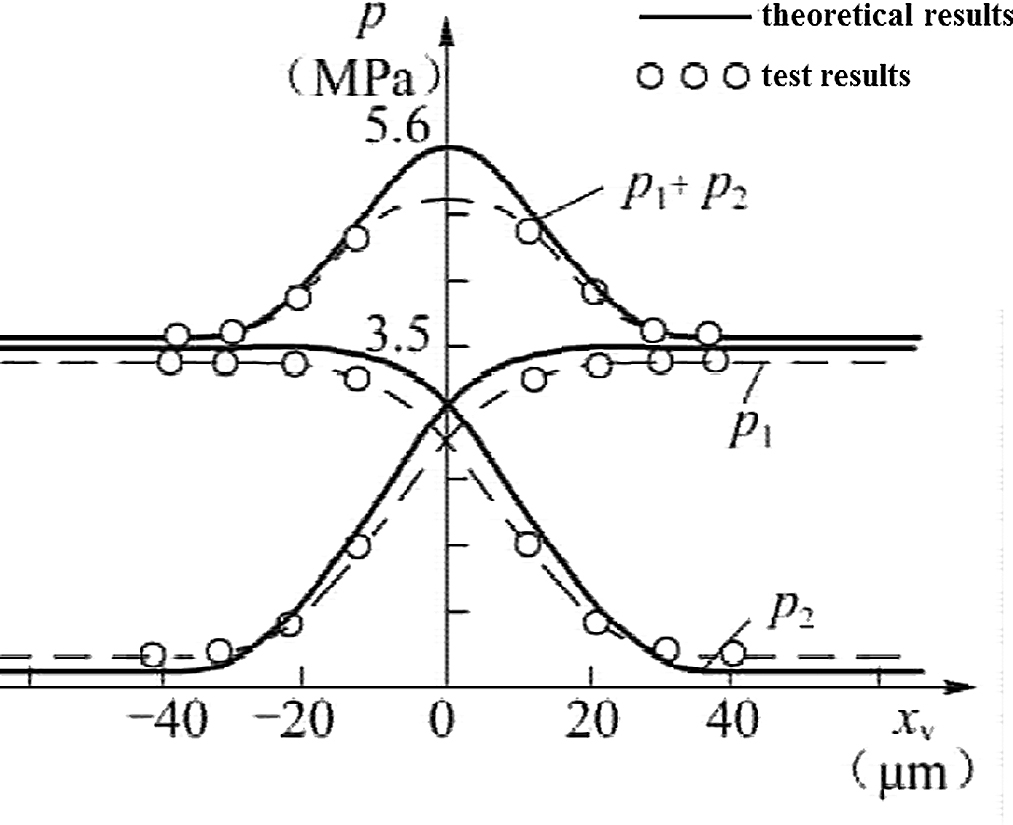
In this paper, the pressure characteristics of two kinds of uneven opening valves are tested, and the results are shown in Figs. 7.8 and 7.9. Fig. 7.8 shows the asymmetric hydraulic valve controlled asymmetric hydraulic cylinder pressure characteristics test results (A
1 = 0.5A
2, Δ1 = 2Δ2), the object hydraulic valve is a symmetrical uneven positive opening asymmetric valve. Fig. 7.9 shows the asymmetric hydraulic valve controlled asymmetric
hydraulic cylinder pressure characteristics test results (A
1 = 0.5A
2, Δ1 = Δ2), the object hydraulic valve is a symmetrical even positive opening asymmetric valve. The experimental pressure characteristics are in good agreement with the theoretical analysis.

To sum up, the proposed method and theoretical formula can be used to evaluate and predict the positive opening amount and pressure characteristics of the hydraulic slide valve, including the following aspects:
- 1. The two control chamber pressures of the axial dimensional symmetrical unequal opening hydraulic valve and valve displacement are nonlinear in function, and the sum of the pressure of the two control chambers is not constant.
-
2. When designing a hydraulic system that bears the load or a loading system, asymmetrical hydraulic valve controlled asymmetrical hydraulic cylinders should be used as much as possible, properly selecting the hydraulic cylinder area A
1 and supply pressure p
s, such as
 , when m=1, so that F = 0.25p
s
A
1, which can ensure the speed characteristics of the system has good linearity.
, when m=1, so that F = 0.25p
s
A
1, which can ensure the speed characteristics of the system has good linearity. - 3. In the flow matching control system, selecting an appropriate value of underlap valve axial dimensional symmetry unequal coefficient m can increase the output power of the slide valve.
..................Content has been hidden....................
You can't read the all page of ebook, please click here login for view all page.