
Chapter 5
Aircraft Electrohydraulic Servo Control Technology
This chapter summarizes the development and progress of aircraft electrohydraulic servo control technology, including principles, materials and methods of aircraft elastic seal under extreme environments, and characteristics and key techniques of aircraft electrohydraulic servo technology. The design method of anti-aircraft missile control executive system is discussed, including comprehensive requirements, discourse processes, main criteria and performance test. Taking the standby energy of anti-aircraft missile as an example, the energy of a missile is classified according to typical application situations; the energy application technology of aircraft combustion turbine is identified, including gas primary energy, combustion turbine, hydraulic system working zone of combustion turbine, etc. The design method of system power matching of a hydraulic steering engine is proposed, best matching the output characteristic of the servo mechanism to the load trace according to load model to achieve the best allocation of energy.
5.1. Electrohydraulic control technology
From the development process of electrohydraulic control technology, the foundation of the current technical level and future development prospects can be seen. This indicates a developing trend of high-power, high-pressure, high-temperature, high-speed, high reliability, digitization and informatization.
5.1.1. Outline of electrohydraulic control technology
The history of hydraulic control can be traced back to 240 BC. The water clock, the first known hydraulic servo mechanism in human history, was invented by the ancient Egyptians. Leaping forwards in time from that, in the 18th century, the European Industrial Revolution brought vigour to hydraulic control technology; many practical inventions emerged; the
appearance of many kinds of hydraulic mechanical device especially hydraulic valve increased the influence of hydraulic technology significantly. Hydraulic components, such as pump, hydraulic press, hydraulic cylinder etc., emerged towards the end of the 18th century. Some significant progresses were obtained in the early 19th century, including using oil as a working medium and driving direction control valves by electricity.
During World War II and the postwar period, electrohydraulic control technology was in rapid development. The wo-stage electrohydraulic servo valve, nozzle flapper component and feedback device were produced in this period. The 1950s and 1960s represented the pinnacle of development of electrohydraulic components and technology; electrohydraulic control technology distinguished itself in military applications, especially in aviation and aerospace. Initially, these applications included radar drives, guidance platform drives, missile launcher control, etc. This later extended to include flight control of missiles, radar antenna locations, enhancing the stability of aircraft flight control systems, dynamic adjustment of radar magnetic control tubes, thrust vector control of aircraft, etc. The applications of electrohydraulic control technology in non-military industry were mainly applied more and more in the machine tool industry. The operating platform positioning servo device of numerical control machines used an electrohydraulic system, with an electrohydraulic servo motor instead of manual operation. Secondly, this technology was applied in construction machinery. Towards the end of the 20th century, the industry applications of electrohydraulic control technology were extended further to fields such as industrial robot control, plastics processing, geological and mineral exploration, combustion or steam turbine control, and automation of movable equipment.
The development of electrohydraulic servo control devices is plentiful and substantial – for example, the servo valve with dynamic pressure feedback, the redundant servo valve, the three-stage servo valve and servo actuator. Electrohydraulic proportional control technology and the proportional valve emerged in the late 1960s and the early 1970s. The purpose of developing the proportional valve was to reduce cost; normally its cost is only a fraction of the servo valve’s cost. The performance of the proportional valve is worse than that of the servo valve, but advanced control technology and electronic devices compensates for this inherent drawback, and brings its performance and function close to those of the servo valve. Rapidly developing electronic technology and devices promote the development of electrohydraulic control technology. The advent of
integrated circuits in the 1970s and the birth of microprocessors enabled machines to carry out mathematical calculations and processing capacity. Electronic (microelectronic) devices consisted of integrated circuits with tiny volume but high output power, very high signal processing ability, very good reproducibility and stability, and very low price. With the support of electronic (microelectronic) control devices, electrohydraulic control technology is developing to digitization, and informatization.
5.1.2. On-board electrohydraulic control technology
Many electrohydraulic control valves have electronic devices with them: so-called on-board electronic devices. This combination erection method, which installs the driver and signal conditioning circuit directly to the valve, has the advantage of reducing the number of connecting lines between the valve and central control system. According to traditional allocation, the valve is close to the actuating mechanism; however, the central control device is located in the electric console which is far away from the actuating mechanism. This means that many long cable and electrical connectors are needed in between to connect them, but many long cable and electrical connectors are the part having worst reliability in an electrohydraulic control system. The combination erection with hidden chips increases reliability because it simplifies cable connection and connectors, or omits them altogether. One electrohydraulic device can have many functions, omits many devices and simplifies the system and operation, as it only needs to send right signal to them. For example, a servo valve can control speed, position, acceleration, force or pressure if it is provided with data from the corresponding sensor, feedback device and control logic/processing device.
Apart from increasing reliability, an on-board electric circuit can also form a kind of coexistence mode, simultaneous existence of distributed control and centralized control. For industrial applications, the preferred device configuration is a programmable logic controller (PLC), which can send instructions to several valves and pumps. Many kinds of functional components, especially those which are suitable for open-loop control, are created at the opportune moment. Some components have flexible transformation making the increasing and decreasing of speed controllable to moderate system impact by switch valve control. These devices are normally integrated and online debugging. When used in high requirement movement control, they are normally assisted by an industrial movement control device to achieve the simultaneous control of accelerate, speed and
position. This device can be an independent applied controller, or can be a plug-in unit of the expansion bus of a PLC. Because of the implementation of serial communication bus standard, a large number of electrohydraulic devices (for example, valve, pump, and solenoid) can be controlled only by a pair of wires.
5.1.3. Developing trend
1. Ultrahigh pressure
Hydraulic technology is well-known for its large output force and high power density; the key is to use high pressure. Developing to ultrahigh pressure is the trend, but the increasing of hydraulic system working pressure is restricted by many factors. Too high pressure brings with it risks: corrosion under high pressure – dirt causes severe wear and tear in flow path; to adapt the very high working pressure, the strength and thickness of wall of components must be increased significantly, and this leads to the increase of volume and mass or the decrease of working area and output volume; under the constant load, the decrease of output volume and working area caused by too-high working pressure leads to the downshifting of the resonance frequency of hydraulic machine, and brings control difficulty. Therefore, it can be anticipated that a series of key basic theories need to be solved to increase working pressure substantially.
2. Energy saving and efficiency increasing
Efficiency is always one of the issues of most concern. A hydraulic drive can easily provide enough power for a load to move, especially rectilinear motion; this is the clear advantage compared with an electric drive. Howevr, because of throttling loss and volume loss, hydraulic drive has greater energy consumption, and not particularly high efficiency. Although a hydraulic drive has unique advantages compared with a traditional mechanical drive, the electric drive industry is progressing rapidly, focusing on small volume and large power, using thinner wire and larger working current. The development and application of room-temperature superconducting materials offers a significant promotion to the application of electric drives; it means energy conservation, and is a developing direction for the future. If the hydraulic system is not developed in a way that allows energy saving and efficiency increases, the electric drive may invade and occupy the current exclusive application area of the hydraulic drive, especially the application areas requiring large acting force, high speed and linear motion.
3. Sensitive element/sensor integrated
Sensitive elements or sensors help to achieving monitoring, control and adjustment of electrohydraulic system parameters, and play an important role in the combination of hydraulic technology and microelectronic control. Integrated sensor structures are being developed, because this kind of structure is conducive to increase the dynamic response and reliability of a system. An electrohydraulic device provides assorted sensitive elements of a sensor. A sensor used by an electrohydraulic system has the ability to store and correct data itself; a microelectronic control device downloads these data and conducts interpretation and translation. The development of a multipurpose interface device enables for users the selection of any kind of sensitive element. The main computer will recognize the type of sensitive element used, such as digital or analogue, serial or parallel, and translate its output. The use of modern control theory, such as state variables feedback control, can increase the response of an electrohydraulic system efficiently. On the basis of dynamic characteristics of valve and other components, this technology requires some key variables, such as internal pressure in the system, in addition to measurement and feedback controlled output. All these state variables need to be sensed and achieve feedback by a sensitive element. In certain systems, using optimized reduced-order state variables feedback can reduce the stabilization time of a loop.
4. Using computer software
Software is crucial to the development of electrohydraulic control technology. Hydraulic components or device with sensors and two-way communication interfaces can communicate all other components or devices and main computer with the help of software. The key parameters of hydraulic components can be stored in a memorizer which can be used directly by a computer; this computer carries out simulations and other calculations to determine if the components are compatible with each other. the main computer can enquire with peripheral equipment equipped with a bidirectional data transmission line about setting parameters using query software, and use these parameters to complete a communication protocol, helping users to set up new peripheral equipment. Once all pumps, motors, valves and hydraulic cylinders have a sensor and bidirectional data transmission line, the computer can not only control and monitor a hydraulic machine through these, but also give this machine complete self-diagnostic ability. The basic performance and qualified performance data of hydraulic components are stored in the large database of
the control/monitor computer. The computer measures the current performance in predetermined time intervals of all components, and compares this performance to basic performance. If the performance is out of qualified range, the computer will send an alarm, and shut down the machine when it is in critical condition. Fully automatic diagnostic ability (health diagnosis) is necessary for future machines, because they are becoming more and more complex, and thus cannot check and remove faults using normal methods.
5. Control and eliminate leaks
Leaks are difficult to solve in long-term problems of fluid power systems. An internal leak in a hydraulic system can lead to energy waste, decreasing of volume efficiency and mechanical efficiency, and affect the dynamic properties and static properties of system. However, an external leak requires closer attention, because it may pollute the environment. Over the years, leaks are always a topic related to environment pollution, and the requirements to ensure a clean environment keep increasing. Effective measures should therefore be used to reduce or stop leaks or eliminate the harm caused by leaking fluid in professional discipline. These measures include improving and perfecting sealed leak-proof technology, choosing proper hydraulic system pipelines, the personnel concerned receiving professional technical training in the maintenance of hydraulic equipment, and developing and adopting environmentally friendly fluid instead of petroleum-based fluid as working medium, such as pure water or biodegradable fluid. Eliminating leaks is one of the most important challenges faced by current hydraulic technology. When a hydraulic system is no longer beset by the problem of leaks, the competitive power of hydraulic technology will increase remarkably.
6. Applying computer-aided engineering
The rise of computer-aided engineering (CAE) enabled hydraulic technology to reach a new level in the 1980s. Using computer simulation, a designer of hydraulic system loop and components can check his or her conception and scheme quickly and economically; this not only saves time but also allows the best results to be achieved. In the early stages, computer-aided design (CAD) was used as a simple means of drawing hydraulic loops and hydraulic components. Nowadays, they are developing to performance prediction field. Using the entity modelling method, one can not only draw an entity graph, but also evaluate performance data such as strength, mass,
centre of gravity and moment of inertia. By looking at the fluid mechanics relationship and virtual experiment/simulating experiment, the designer of hydraulic components will be able to predicate the hydraulic mechanics performance of components. This evaluation technique before prototype has been applied widely. Computer-aided design of a hydraulic system needs an effective CAD program package. Each component in the system has its independent mathematic model, and the program therefore includes a very large component modelling base. Establishing a component model requires many parameter data, and these data cannot normally be obtained from the manufacturer. Therefore, although there are many CAD programs for hydraulic systems, they are not widely applied. Models from software suppliers are not perfect normally, but building models needs expertise; and it is not an easy task to move from mathematic expression to real hardware performance and eliminate the difference between the model and real hardware. These models must include not only steady-state results, but also differential equations forming a dynamic response basis. Dynamic performance evaluation is a necessary task when simulating a system, as it may otherwise lead to imperfect simulating results. Before the design of a hydraulic loop, high-level engineering analysis is needed; this is required by the original device manufacturer and by hydraulic device users. In the case of a lack of meaningful data specific to building a mathematic model, it is not easy to establish this model. The establishment of a mathematic model of hydraulic components relays to test in laboratory, otherwise it is not easy to achieve. Establishment of a mathematic model of a pump and hydraulic motor requires the manufacturer to provide leak and frictional coefficients. Other key data for establishing model such as a continuity equation needed by measurement curve, leak coefficients varied with temperature and pressure, and transfer function or nonlinear differential equation, are provided by manufacturers to users. Once these points and requirements are identified and responded to and actualized by manufacturers, a mathematic model of hydraulic components will be as common as an assembly drawing. This also offers a significant contribution to modelling or simulation technology.
5.1.4. New material
The creation and application of new material enable electrohydraulic technology to evolve and change. For the most-used ferrous material in hydraulic system, if it can have higher strength without increasing cost and
decreasing machinability, hydraulic machinery will be more powerful and reliable. Ceramic materials have already been used in hydraulic systems and achieved a degree of success. The increased performance of magnetic materials (magnets) had a remarkable effect in promoting the development of electrohydraulic technology. If the magnetic saturation current of magnetic material could be increased, a coil or solenoid with same number of turns could produce greater electromagnetic force. As the electrical mechanical interface of electrohydraulic valve, solenoid produces larger force produced, this means producing of direct driven larger flow hydraulic valve nearly without additional cost. A high-performance magnet has large magnetic saturation current and high magnetic induction, allowing large current driving, which produces a greater electromagnetic force. This force can be used effectively to accelerate slide valves, and leads to wider dynamic bandwidth or higher frequency response. When a solenoid that can produce a greater force is used as an electrical mechanical interface by an electrohydraulic valve, the pre-stage can be omitted; this creates conditions for developing a larger-flow, quick-acting, low-cost electrohydraulic valve.
5.1.5. Electrorheological fluid technology
Electrorheological fluid (ER fluid) is a free flow suspension liquid in a free state. Once under the action of electric field, it will solidify quickly, appear to be sticky and have a thick, gel or hard character according to the strength of the electric field. This feature makes it ideal to be applied in valve, damper and power transfer devices of hydraulic systems and mechanical systems. ER fluids respond to electric signals extremely quickly, and can finish the change of state from liquid-solid or solid-liquid in 1 ms. The degree of cure is proportional to the strength of electric field. This makes the fluid suitable to be controlled directly by an electric device, such as a microcomputer; and this is its greatest important advantage. The possibility of ER fluid technology application is based mainly on its two features: low input electric power and quick response speed. Although working voltage may be as high as several thousand volts, current density is very low, normally lower than 10 mA/cm2, and can normally be handled by solid electronic devices. Because the working current is very small (less than 2 mA), input electric power is very low; the small signal response of ER fluid approximates to a first-order link, and its corner frequency is about 1 kHz. This value is an order of magnitude higher than the corner frequency of most electromagnetic devices, including electrohydraulic servo valves, and
avoids the electromagnetic effect, which is the unique characteristic of magnetic coils. ER fluid is suitable to use in pulse-width modulation control, can reduce energy consumption, simplify design, reduce moving parts, reduce abrasion and extend lifetime. However, it also has some practical problems. Firstly, the curing strength is not high enough; normally shear strength is smaller than 5 kPa/mm, and so the torque transfer is limited. Further increasing curing strength needs higher electric field strength (for example, increasing from 2 kV to 4 kV) or increasing free viscosity of fluid. However, a high electric field strength corresponds to high current consumption. There are problems in terms not only of safety but also of economy. Too-high free viscosity of fluid will increase the surface abrasion of devices, and particle deposition will easily occur. Therefore, the increasing of electric field strength and free viscosity is limited, and the increasing of curing strength has no room for improvement. Secondly, the temperature stability of ER fluid (especially ER fluid containing water) is poor, so the working temperature is normally limited to 0–80 °C. Although these defects limit the application of ER fluid technology, this technology has obtained meaningful progress over the last 20 years. ER fluid without water is close to practical application. ER fluid has great application potential, and may represent the future hydraulic technology.
5.2. Elastic O-type ring sealing technology
There are many sealing forms, such as clearance seal, elastomer compression deformation seal, mechanical seal and ferromagnetic fluid seal. An elastomer compression deformation seal is the sealing form most used, and elastic O-type sealing ring (hereinafter referred to as an O-type ring) is one of the most common structures. O-type ring has more than 70 years of history since it was first patented in 1939. In the 1940s and early 1950s, the O-type ring was mainly used in military areas such as aircraft hydraulic systems, and expanded to other industry areas later. Sealing technology has been developing for more than 70 years, but the basic structure of O-type ring remains unchanged, demonstrating its strong vitality.
5.2.1. Structure and sealing principle of O-type ring
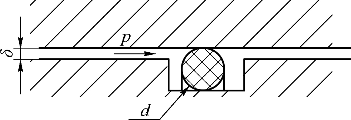
Just as its name implies, the O-type ring is an elastic ring with a standard circle section. It achieves sealing using elastic deformation produced by compress closing to the surface of sealed member to form press fit to
prevent flow passes as shown in Fig. 5.1. The key element of sealing is that the compression quantity or compression ratio of an O-type ring in its embedded state must accord with the component size, application type, fluid pressure and material of the O-type ring, otherwise an effective seal cannot be achieved, and this will damage the O-type ring.
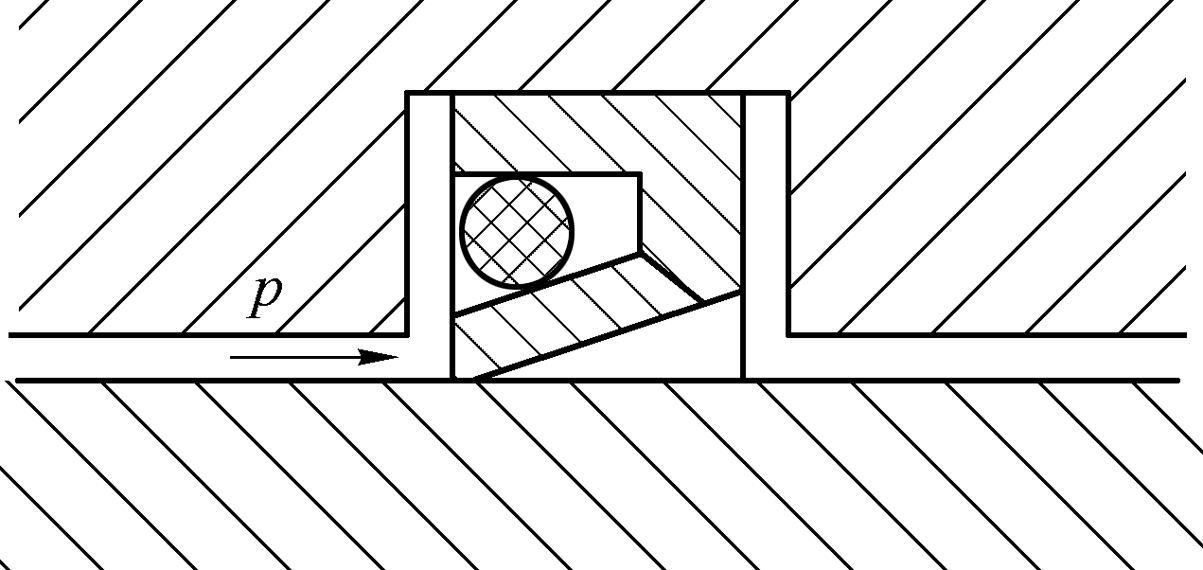
Apart from directly compressed elastic deformation sealing, the O-type ring can also be used as the energy component of a U-type combination seal ring. The O-type ring is embedded in the U-groove of the section of polymer U-type ring, and forces the mouth of the U-type ring to open widely to cling to the sealed surface to achieve seal, as shown in Fig. 5.2. In this structure, the elastic force of the O-type ring acts on the inside of the U-type ring mouth to provide a low-pressure sealing force, and a high-pressure sealing force is provided by fluid. The sealing principle of the O-type ring is shown in Fig. 5.3.
5.2.2. Characteristics of O-type ring sealing
- 1. Simple structure, good reliability.
- 2. Low price, economical and practical, quantity production, guaranteed batch supply.
- 3. Can compensate for radial runout in tolerance range.
- 4. Omnidirectional seal (radial, axial or in any direction).
- 5. Wide applicability, suitable for all types of seal application (face seal, radial seal, static seal and dynamic seal).
- 6. Can be repeatedly used in extreme working range (pressure, temperature, speed and cycle).
- 7. No protective coating required.
- 8. Material selection can be made according to application.
- 9. Easy to install – normally no special tools are required.
- 10. No fastening required.
5.2.3. Material of O-type ring
O-type ring normally is made of elastic natural rubber or synthetic rubber. Synthetic rubber is made from many chemical ingredients after the curing process. Ingredients normally include: polymer (elastomer), inert filler (carbon black or mineral filler etc.), intensifier, catalysator, activating agent, retarder and curing agent, anti-degradation agent, plasticizer, process auxiliary agent for promoting molding, special additives (pigment, flame retardant, etc.).
Currently, dozens of rubber materials are widely used; the formulae and proportions for each material are not the same, and therefore the characteristics of material are not identical. However, the main characteristics and features are as follows:
- 1. Extensibility. Natural rubber has the best.
- 2. Resilience. Natural rubber has the best too.
- 3. Tensile strength. Natural rubber, urethane and polyurethane rubber have high tensile strength; the tensile strength of butylbenzene, polyacrylate and fluorosiloxane rubber is bit lower.
- 4. Tearing resistance. Natural rubber, urethane and polyurethane rubber have the best; the tearing resistance of silicone rubber and fluorosiloxane rubber is a bit poorer.
- 5. Anti-compression permanent deformation. Urethane, polyurethane, silicone fluorosiloxane and fluorocarbon rubber have the best. Anti-compression permanent deformation of polyacrylate and chloroprene rubber is a bit worse.
- 6. Corrosion resistance. Natural rubber, butylbenzene, allyl ethylene, chloroprene, butyronitrile, urethane and polyurethane rubber have very good corrosion resistance; silicone rubber and fluorosiloxane rubber are not good at corrosion resistance.
- 7. Cold resistance and heat resistance. Allyl ethylene, silicone and fluorosiloxane rubber have the best cold resistance and heat resistance. Polyacrylate and fluorocarbon rubber is heat resistance but not cold resistance. Natural rubber, butylbenzene, urethane and polyurethane rubber are good at cold resistance, but bad at heat resistance.
- 8. Weather-ageing resistance. Natural rubber is the worst at weather-ageing resistance; butylbenzene and butyronitrile rubber are normal; most of the others have very good weather-ageing resistance.
- 9. Refractoriness. Fluorocarbon rubber is the best, and then chloroprene; silicone and fluorosiloxane rubber; most of the others are not fire-resistance.
- 10. Water resistance and steam resistance. Allyl ethylene rubber is the best; natural rubber, urethane, butylbenzene, butyronitrile, and fluorocarbon rubber are slightly worse; polyacrylate and polyurethane rubber have poor water resistance and steam resistance.
- 11. Acid resistance. Fluorocarbon rubber is the best; polyacrylate, urethane and polyurethane rubber have poor acid resistance.
- 12. Oil resistance. Polyacrylate butyronitrile, urethane and fluorocarbon rubber have very good oil resistance; natural rubber, butylbenzene and allyl ethylene rubber are not oil resistant.
- 13. Ozone resistance. Apart from natural rubber, butylbenzene, butyronitrile and urethane rubber, most other rubbers have very good ozone resistance.
5.2.4. Selection and design of O-type ring
The sealing and application of O-type ring are deceptively simple; it is not easy to obtain good seal results, and proper selection and the right design are required. The selection and design of an O-type ring must be based on a concrete application environment to ensure that the O-type ring coordinates or adapts to application environment factors such as dimension of sealing member, type of sealing, fluid medium, fluid pressure and environment temperature. Therefore, the following principles must be followed:
- 1. Specifications and dimensions of the O-type ring must be coordinated to the sealing member to ensure that the compression of the O-type ring is appropriate and to obtain effective sealing and good system working performance. If these two factors are not coordinated, the result will be improper compression quantity or compression ratio (too big or too small). When the compression quantity or compression ratio is too small, the contact stress between the O-type ring and sealing surface is not enough to seal; when the compression quantity or compression ratio is too great, the stress acting on the O-type ring is too high and permanent compression deformation easily occurs. Under dynamic sealing conditions, the O-type ring is acted on by significant friction force and rises to quite a high temperature. This can not only accelerate wear and ageing of the O-type ring, but may also affect the dynamic characteristics of the system; the results are very serious under high-speed, high-frequency application conditions. the compression quantity or compression ratio (relative compression quantity) is the measurement of the compression deformation of the O-type ring; the compression quantity is the absolute deformation quantity, while the compression ratio is the percentage of the absolute deformation quantity of the O-type ring to the diameter of its section. The latter is the scale that reflects compression status more scientifically and rationally than compression quantity, and is normally the scale used. The compression ratio of the O-type ring must change according to the different types of applications. The following empirical data based on large amounts of surveys and statistics can be selected and consulted in the design phase. A static seal selects a bigger compression ratio: 15–25%; special application can reach 34%; reciprocating type radial dynamic sealing must select a slightly smaller compression ratio: 12–17%, while rotary type dynamic sealing must select the smallest compression ratio: 5–10%.
The depth of groove of an embedded O-type ring must be coordinated to the compression ratio of the O-type ring, and the width must be not smaller than 1.25 times of the diameter of the O-type ring section. The maximum value of clearance of diameter (2g) for an O-type ring without a retainer ring is shown in Table 5.1.
- 2. The specifications, dimensions and material of the selected O-type ring must be coordinated to the application type, such as surface seal selecting a bigger compression ratio, while the radial seal selects a smaller compression ratio. A static seal selects a bigger compression ratio, but a dynamic seal selects smaller compression ratio; a reciprocating type dynamic seal selects a bigger compression ratio, but a rotary type dynamic seal selects a smaller compression ratio. The O-type ring material used in a dynamic seal must have proper hardness and good wear resistance and heat resistance. If the heat resistance of the selected O-type ring material is not good enough, sufficient lubricant should be added to reduce friction. If the fluid medium is mineral oil, this is lubricant itself, and there is therefore no need for an additional lubricant.
-
Table 5.1
Maximum value of clearance of diameter (2g) for an O-type ring without retainer ring Pressure Hardness of O-type ring (spring hardness, HS) Clearance of diameter (2g) Pressure in application (MPa) Above 4.0 Above 4.0Below 6.3Above 6.3Below 10.0Above 10.0Below 16.0Above 16.0Below 25.070 0.35 0.3 0.15 0.07 0.03 90 0.65 0.6 0.50 0.30 0.17 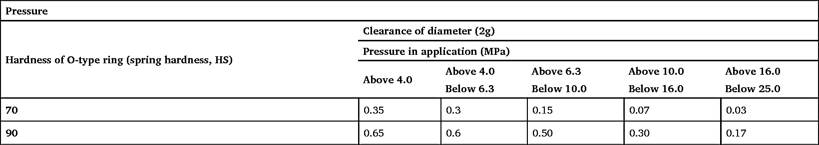
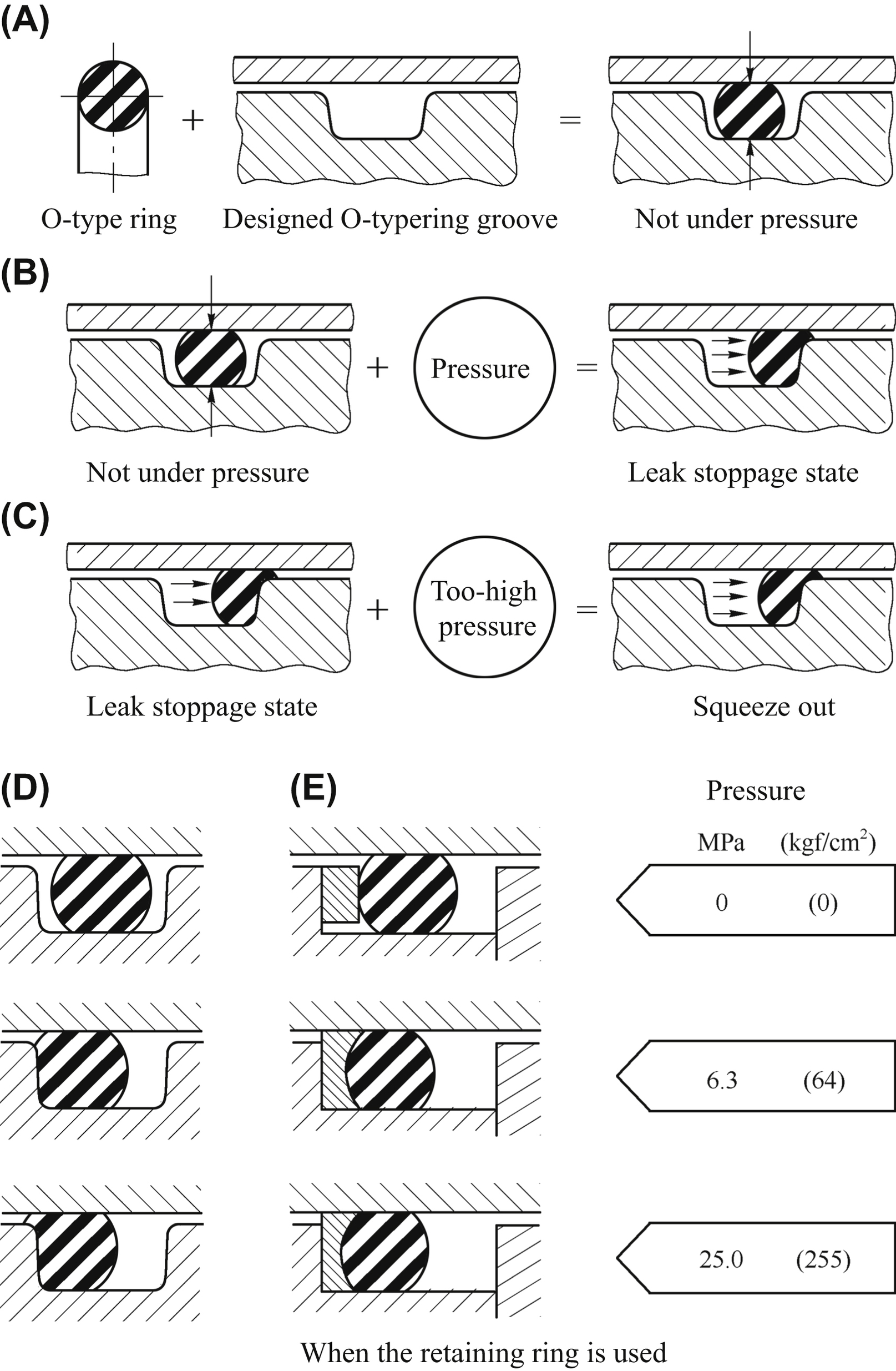
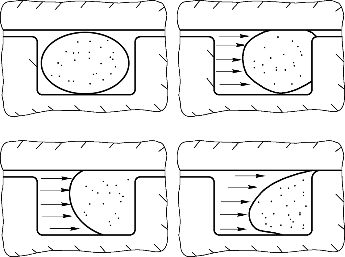
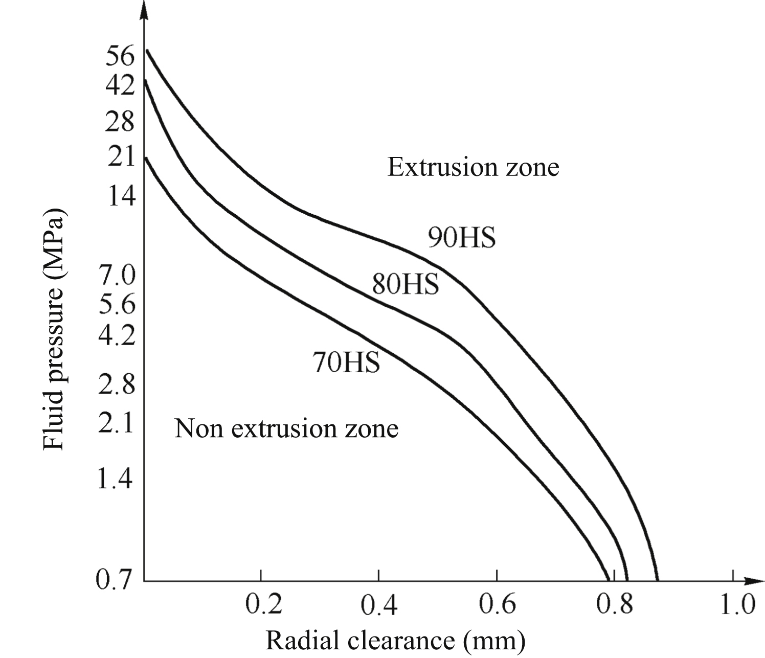
- 3. The material of an O-type ring must be coordinated to the fluid pressure. Fluid pressure can reach 30–40 MPa in the trend of ultra-high pressure nowadays; this is a challenge to sealing technology. Many problems will come with high pressure, one of which is whether the seal ring can resist the high pressure and survive. In radial seal condition, the O-type ring will be compressed into sealing clearance by high pressure fluid and lead extrusion failure as shown in Fig. 5.4. The softer the material is and the bigger the clearance is, the more easily this crushing damage will occur. Under the action of high-pressure fluid, the cylinder barrel expands and cannot be ignored to increase the sealing clearance and intensify extrusion. Thus, to avoid O-type ring damage due to high-pressure fluid crush, elastic material with high hardness and high anti extrusion deformation ability must be chosen. Fig. 5.5 shows the relation characteristic curves between the fluid pressure and the allowable radial clearance of three kinds of shore hardness (70 HS, 80 HS and 90 HS) O-type rings. These curves are actually the extrusion limit of an O-type ring. The area below cures is the area without extrusion, and is the normal working area of an O-type ring; the area above cures is the area that extrusion occurs, and the O-type ring will be compressed when working in this area. From Fig. 5.5, the relations between fluid pressure, radial clearance and hardness of the O-type ring can be established: the higher the fluid pressure is, the smaller the allowable radial clearance is; the higher the hardness of the O-type ring is, the higher its bearing capacity to high pressure is, and the larger the allowable radial clearance is, the higher the anti-extrusion ability is. The cures in the figure are obtained on the basis of 100,000 cycle experiments on 1 HZ frequency from zero to the maximum value. The temperature of experiments is below 70 °C. It should be noted that the cures shown in Fig. 5.5 cannot be used for O-type rings made of silicone rubber and fluorine rubber; the corresponding pressure should be halved for these rings.
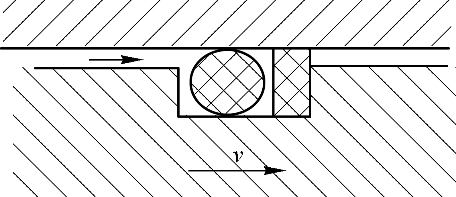
When for some reason high hardness materials cannot be chosen, a plastic protective ring with low friction coefficient is used to prevent the O-type ring from being pushed into clearance, as shown in Fig. 5.6. The protective ring can be on one side of the O-type ring or both sides, according to the acting direction of pressure. The materials of the protective ring most are polytetrafluoroethylene (PTFE). The O-type ring may have permanent compressive deformation under the long-term action of high fluid pressure, so materials with good elastic resilience should be chosen.
- 4. The material of the O-type ring must be coordinated to the application temperature. That is, the temperature limit of material or the allowable temperature range must cover the application temperature range. If the O-type ring works outside the temperature limit of its material, it will lose its sealing function. The elasticity of the O-type ring obviously decreases under too-low temperature; it presents in an ossified state and cannot deform enough to produce the elastic compressive deformation needed by sealing. When the temperature returns to normal, the O-type ring’ characteristics can normally return to their original states. However, the effect of high temperature is more severe. Under too-high temperatures, the elastic material will be hardened, undergoing ageing and oxidation, and this will cause the O-type ring t o lose elasticity quickly. Dents and cracks appear on the surface; permanent compressive deformation and abrasion phenomenon occur, resulting in failure of the sealing. Apart from too-hot environment temperature, kinematic friction due to high-speed movement and too-great compressive deformation can also produce local overheating to damage the O-type ring. Therefore, the coordinated material of the O-type ring must be chosen according to the application temperature range.
- 5. The material of the O-type ring must be coordinated to the fluid. The O-type ring is under the fluid medium for a very long period of time, if the material of the O-type ring is not coordinated to the fluid medium, the ring may lose elasticity due to swelling, shrink, soften or become brittle, thus losing its sealing ability. Therefore, choosing the material of the O-type ring must be done to ensure that its characteristics will undergo no obvious change under the acting of an application fluid medium.
The above are some basic principles that the choosing and design of an O-type ring must follow. These principles are not connected to each other. For a specific application, normally only some of them can be followed. Comprehensive consideration is needed, and compromise is necessary.
5.2.5. Protection and fault prevention of O-type ring
Only an intact O-type ring can ensure good sealing efficacy, so it is necessary to protect it. By following the above principles, sealing failure due to improper choice and design and faults such as permanent compressive deformation of the O-type ring, abrasion, crushing damage, aging, oxidation and elasticity losing etc. can be avoided. Apart from these, the O-type ring needs to be protected from damage caused by other aspects as follows.
- 1. The rubber material of the O-type ring must be fully vulcanized to improve resilience, increasing the ability to resist permanent compressive deformation.
- 2. A too-coarse metal component surface, sharp edge and improper assembly method can easily cause damage to an O-type ring. The metal component surface must be smooth; sharp edges should be chamfered or rounded; and care should be taken in the assembly process; using a protecting jacket for the metal component when needed to avoid cutting damage to the O-type ring. Adding lubricant is also an option to consider in the assembly process.
- 3. Increasing the concentricity of components and decreasing the irregularity of radial clearance due to eccentricity ease the extrusion of the O-type ring.
- 4. Abrasive impurities in fluid is another cause of O-type ring abrasion. A filter must be used to remove impurities, or an abrasion-resistive material for the O-type ring, such as nitrile carbide and urethane.
- 5. The O-type ring may produce many tiny cracks perpendicular to the stress direction due to ozone erosion, so ozone resistance materials should be used.
The essential aim of using the O-type ring is to seal effectively and avoid fluid leaking. The O-type ring can finish its mission in the long term and without fault only when the correct choices are made and design and protection are carefully dealt with.
5.2.6. Conclusions
As mentioned above, the basic structure of O-type ring has remained unchanged for 70 years, but O-type ring sealing technology is in development, especially in the research and development of material, design, manufacture, experiment and appraisal of the O-type ring. In research and development of material, the most remarkable result is engineering polymer sealant. Its abrasion resistance, extrusion resistance and high/low temperatures resistance
are all better than those of rubber elastomer; using a special formula combination can produce an engineering polymer sealant with the engineering characteristics required for special applications. There are currently more than 20 types of engineering polymer sealant, among which polyurethane is used most commonly. There are three main kinds of polyurethane material: MDI, TODI and PPDI, and the characteristics of PPDI are the best. This has very high compressive deformation impedance and good resilience, a wider temperature range than those of rubber materials, and its lifetime is more than 10 times greater those of rubber materials.
Remarkable results of materials improvement based on the original foundations are obtained. For example, changing the fluorine content in a fluorocarbon polymer improves the chemical stability and thermal stability of the polymer. Every kind of elastic material can be used as a sealant to meet the requirements of different application environments.
With the development of computer technology, the material choice, design and experimental analysis of a seal ring can be carried out by computer. Many kinds of software packages for PCs have been developed to achieve many functions. For example, Parker Hannifin Corporation, one of the biggest fluid power products companies, developed the InPHorm series software package, which can help designer to finish the overall design of O-type ring. Engineering calculations can be checked by software, and the selection of the O-type ring can be made by using this software package. Redundant technique has been used in many sealing designs to improve the reliability of the seal.
The nonlinear finite element analysis method has been applied to elastic sealing design successfully; a variety of finite element analysis software packages allow the nonlinearity of elastic materials to be detected more precisely. Characteristic analysis of elastic materials has made considerable progress too; this technology has been used in prediction analysis and fault-model-effect analysis. The information obtained from characteristic analysis significantly provides a basis to determine the proper sealing method. The purpose of more complex experiments is to describe precisely the harmful effects to elastic materials from adverse environments, especially functional test-bed simulating working conditions. The stress-relaxation test of elastic materials can be carried out by improving the technology and devices of the test. The aim of characteristic analysis is for the potential fault model of elastic materials to be predicted more precisely before the fault occurs. In addition, the sealing life prediction and analysis can be carried out.
O-type ring sealing is a low-cost and multipurpose kind of sealing type. It is full of vitality because it has comprehensive advantages incomparable to other kinds of sealing type. Appropriate choices and design and careful protection should guarantee the effective working of an O-type ring in the long term. The principles and details mentioned above tie in with this theme. However, it must be noted that an O-type ring sealing is not always the best choice in a situation; sometimes other types may be more suitable. Sealing technology is not sophisticated technology but it is key, and can normally determine the success or failure of a project. Advanced sealing technology is the production of basic research and modern high-tech means; the target of the development of O-type ring sealing technology is to achieve zero leakage.
5.3. Aircraft electrohydraulic servo technology
Aviation and aerospace have high requirements in terms of electrohydraulic servo technology; they roughly reflect the professional level of electrohydraulic servo control technology. The development of electrohydraulic servo technology involves many areas, such as system and components design and research, materials, testing, manufacturing technology, etc. From the overall view of major, high power, high pressure, high temperature, high speed, high reliability, digitization and informatization are the main focuses of the process of development, and achieved results of historic significance.
5.3.1. High power
Aerospace vehicles and modern production equipment in modern times have notable features such as high capacity, high efficiency and high reliability. As the drive and control device, electrohydraulic servo system accordingly has the trend of developing high-power. Taking DC series passenger aircraft – DC-6 (1950), DC-7 (1955), DC-8 (1960) and DC-10 (1971, 300 seats), of American civil aviation, for example – the power of their hydraulic systems are 19 kW, 24 kW, 67 kW and 340 kW, respectively, having increased 17 times in 20 years. The increasing of the power of hydraulic systems in the space field made sudden progress – for example, the power of Saturn rocket V-2 (1940) hydraulic system is 0.42 kW, and the power of hydraulic system of the first stage of Saturn-V rocket (1969) reaches 462 kW. Table 5.2 lists some application examples of a high-power hydraulic system.
Table 5.2
In the process of the development of hydraulic system power to high capacity, a series of technology problems have been solved as follows.
- 1. Mass reduction. Limiting the mass of a structure to reduce the power mass ratio of system, the system obtained excellent technical performance and economic effects. To do this, reasonable design (such as integration of components and oil pipeline, and structural parameter optimization) is required; high-strength light alloy (such as aluminium or titanium) and high magnetic energy grade magnetic material (such as rare earth magnet steel) are used; the technology progress is obvious. Table 5.3 lists the update status of the main technical indexes of the American DC series passenger aircraft hydraulic pump.
In the high-power hydraulic system of giant rockets (such as the first stage of Saturn-V), its hydraulic pump (4×350 L/min) diverts fluid from the conveying system of engine propellant (RP-1 kerosene). The working pressure is 13.7 MPa and the working medium is RP-1 kerosene, simplifying the system structure and reducing mass.
- 2. Saving energy consumption. The supply of hydraulic energy is self-regulation according to the change of load through hydraulic pump flow to reach power matching, smallest energy loss, reducing system calorific value and elongating working lifetime. A volume-adjustable hydraulic pump is used instead of a constant rate pump when the hydraulic power of passenger aircraft is over 60 kW. In civil industry, the research of regulatory form and characteristics is developed; various forms of energy-saving pumps are developed. In the hydraulic aspects of heavy industry, devices use micro-computers to control the flow of a volume-adjustable hydraulic pump; its input is load, which is the corresponding working condition spectrum of pressure and flow. A multi-pressure hydraulic system is also developed; for example, the working pressure of an American DC-80 passenger aircraft hydraulic system is 20.6/10.3 MPa, and the low pressure is used when aircraft is in cruising. In the 30,000 tons forging press of American A. O. Smith Co., its hydraulic system has three kinds of pressure model: 20.6, 24 and 44 MPa. Low pressure and large flow are used in fast idle condition, while high pressure and small flow are used in heavy duty slow speed.
-
Table 5.3
Update status of the main technical indexes of the American DC series passenger aircraft hydraulic pump Airliner model Pump power (kW) Power mass ratio Repair time (h) Cost per kilowatt (%) DC-6 19 0.43 1500 100 DC-7 24 0.36 1500 70 DC-8 67 — 1600 — DC-10 340 0.29 8000 50 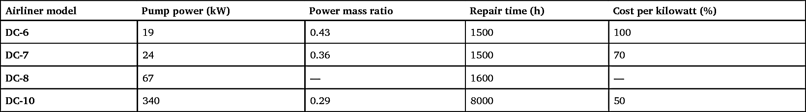
- 3. Hydraulic components. Large-capacity hydraulic components are developed, such as the three-stage electrohydraulic servo valve. For the three-stage electrohydraulic servo valve used by the Saturn-V rocket, the diameter of its spool of slide valve was 25.4 mm, the trip was ±2.79 mm and flow was 510 L/min. A dynamic pressure feedback electrohydraulic servo valve was developed and applied to swing a high-power rocket engine nozzle (mass 4000–8000 kg); it controls a heavy inertia load motion to achieve dynamic damping, suppress system resonance and ensure a wide passband.
- 4. Manufacturing technology. The processing requirements of a high-power system large piece is high. The following technology need to be solved: heavy centrifugal casting, heat treatment, precision machining of inner hole, surface treatment, static strength and sealing test. In an actuating cylinder (16 pairs) of a hydraulic weighing platform of a giant rocket erecting and transferring vehicle, the maximum dimensions are 680 mm × 534 mm × 2 540 mm (inner diameter × external diameter × length). The actuator added a test static load 22 of 701 tons; the oil cabin pressure had no decrease in 24 hours; and the piston position had no shift.
5.3.2. High pressure and high temperature
1. High pressure
Since the 1940s to the present day, the normal working pressure of hydraulic systems has increased from 5 MPa to 27.4 MPa. In the 1980s, Americans developed the 55 MPa working pressure hydraulic system to
replace the original 20.6 MPa working pressure for the F-14 fighter. They finished a full system ground simulation test and single channel flight test, and the prototype ran for 520 hours. After increasing the system’s working pressure, the mass was reduced 30%, and volume was reduced 40%, as shown in Table 5.4 in detail.
Table 5.4
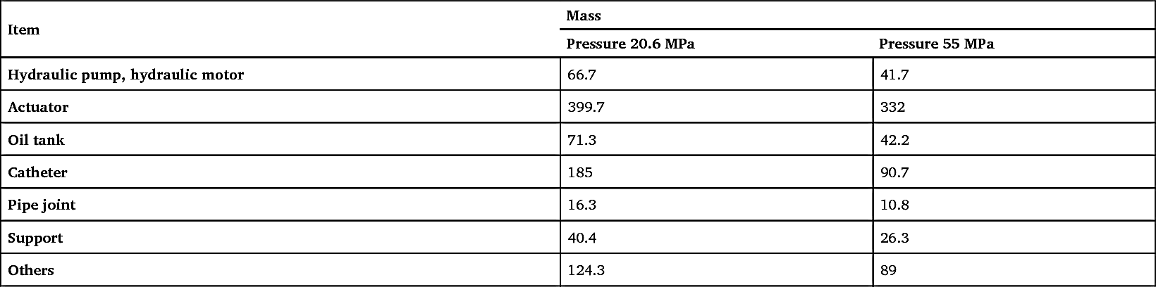
The research on working pressure by considers that the best working pressure of an aircraft hydraulic system is 27.4 MPa – not increased too much compared with the standard pressure 20.6 MPa in common use before. The so-called best working pressure is still a controversial issue. In order to reduce structure dimension and system power mass ratio, military aircraft and ground devices developed a high-pressure hydraulic system, as shown in Table 5.5. Table 5.6 lists the hydraulic pump and electrohydraulic servo valve products distribution situation of the hydraulic industry in Europe and America according to working pressure in 1988.
2. High temperature
High temperature working environments (such as engine bay, metallurgical equipment) and heating temperatures rise due to the high speed, heavy load and long-time running of hydraulic systems. Because of the limit of
structure mass and space position, only depending on forced cooling or heat insulation cannot maintain the normal ground working temperature; recently developing high temperature hydraulic system has become a reality. The oil temperature of the Trident missile hydraulic system is 204–260 °C. In the American high-altitude reconnaissance aircraft SR-71, the working temperature range of its hydraulic system is -54–315 °C. The hydraulic component installed in engine bay is covered by a heat shield (7.6 mm thickness) which scarfskin made of inconel foil to limit the temperature of hydraulic oil below 315 °C.
Table 5.5
3. Problems caused by and key technology developed in response to high pressure and high temperature
- 1. Sealing material. A rubber sealing ring can accelerate tensile ageing, causing crushing damage, and reduce the reliability and service lifetime under high pressure. Therefore, a metal tubule O-type sealing ring was developed; this material consists of stainless steel and inconel. Another solution is to develop a heat-resistant material with high stability and a low friction coefficient, such as fluoroplastic (allowable working temperature 315 °C), and adding glass fibre and molybdenum disulphide. An American space vehicle hydraulic system (204 °C) uses the Hviding E60C synthetic rubber sealing element.
- 2. Hydraulic oil. Under high pressure and high temperature, the stability of hydraulic oil will decrease, as will the viscosity; lubricity will worsen and accelerating parts will be worn, and the oil circuit damping characteristic will be affected. In order to increase shear stability, heat stability and flame resistance of hydraulic oil, Americans developed synthetic hydrocarbon hydraulic oil MIL-H-83282, and used this in the hydraulic system of F-14 fighters and space vehicles. Normally hydraulic systems using hydraulic oil MIL-H-5606 are compatible with this new oil. Table 5.7 lists the main index of two kinds of oil.
-
Table 5.7
Main index of hydraulic oil MIL-H-5606 and synthetic hydrocarbon hydraulic oil MIL-H-83282 Index MIL-H-5606 MIL-H-83282 Flash point temperature (°C) 93.3 210 Autoignition temperature (°C) 243.3 371 Viscosity (mm2/s) (54°C) 10 10.28 Maximum viscosity temperature (°C) -53.9 -40 Shear stability, viscosity change rate (%) (54 °C) -14.28 -0.69 - 3. Leakage loss and service life. Increasing the working pressure and temperature will certainly increase the leakage loss of a hydraulic system, and decrease volume efficiency. To limit leakage loss, it is necessary to reduce fitting clearance and increase manufacturing accuracy; at the same time, precision movable pairs will be not stuck when components are loaded and deformed by heating. Under high temperature, the lubricity of hydraulic oil becomes poor, or an annealing effect occurs on the hardened surface of the part, speeding the abrasion of the movable components. In the USA, the design of the aircraft hydraulic pump was improved in order to increase the working temperature of oil from 135 °C to 204 °C and the component structure and material were changed, with high temperature wear-resistant coating being used. The mass of the test prototype increased 10%, but the working life was only one-fifth that of the original.
- 4. Structural mechanical properties. Structure is easy to deform under high temperature and high pressure; materials have high temperature creep; elastic elements produce high temperature relaxation. Friction speeds the abrasion of material under high temperature.
5.3.3. High speed
When the output flow of a hydraulic pump is constant, increasing the speed can reduce the flow per revelation, therefore reducing the dimension of the hydraulic pump and reducing the weight. In addition, the development trend of high speed of prime mover also has the requirement of high speed for a hydraulic pump. The typical power transmission form of a rocket electrohydraulic servo system is turbine-output shaft of pump (power system propellant delivery)–decelerator–hydraulic pump. In order to reduce volume, lighten mass and increase efficiency, it is necessary to get rid of the decelerator to increase the speed of the hydraulic pump for matching the
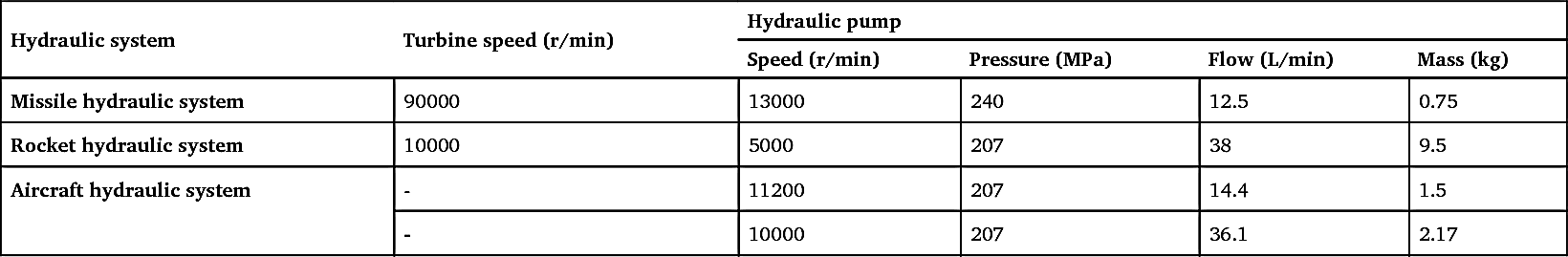
requirement of high speed. In the meantime, when increasing hydraulic pump speed, to maximize the pump’s working life, it is necessary to achieve resistance to overheating and wear of components – for example to develop heating-resistant, abrasion-resistant sealing materials and metal coating, using high-speed precision bearing, etc. In order to ensure sufficient oil absorption of the hydraulic pump at high speed, the absorbing pressure of the pump needs to be increased. It is necessary to increase the pressure of the oil tank or to add a pre-stage pump to increase the pressure in advance. The pre-stage pump can work at low speed. Table 5.8 lists some application examples of aircraft hydraulic pumps at different speeds.
Table 5.8
5.3.4. High reliability
An electrohydraulic servo system under extreme environment may have various failure modes, such as servo valve (nozzle, orifice) block, slide valve clamp, input disconnection, feedback broken circuit, zero shifting over limit or sealing failure. Firstly, it is necessary to use methods to improve reliability in design, to ensure absolute safe working.
1. Component integration
A hydraulic integrated block is commonly used; this reduces or eliminates the need for a catheter and connector. The application of plug-in units increases maintainability; integral combination simplifies installation and increases adaptability to vibration and environmental impacts.
2. Mechanical feedback is used instead of electrical feedback
In electrohydraulic servo actuators used by American militia missiles, such as the Saturn-V rocket, space vehicle and Apollo lunar simulator, their
position feedback is mechanical feedback. This device has the ability of ‘failure → return to zero’ and ‘fault → safe’, compared to potentiometer feedback and differential transformer feedback. This saves a considerable quantity of connecting cables, connection welding spots and corresponding electric circuits; it also improves reliability. However, the requirements of structure manufacturing precision are relatively high.
3. Redundancy design is adopted in key parts
Redundancy design is normally adopted in parts like hydraulic energy sources, electrohydraulic servo valves, actuators, etc.
- 1. Parallel hydraulic system. Large aircraft and space vehicles use parallel hydraulic systems without exception. The American space vehicle orbiter has four independent hydraulic sources, supplying oil to each machine of the control system through the centre hydraulic combination, forming the whole system. Each hydraulic source has 50% (whole hydraulic source) working ability. If one hydraulic source fails, the whole system can still work; if a second hydraulic source fails, the system can still ensure safe return, which means it has a fault working/fault safe ability.
- 2. Double tandem structure. This structure is used in American space vehicle orbiter rudders, in the electrohydraulic servo actuators of undercarriages. The rudder is driven by four actuators (in a double tandem layout), and each actuator provides 50% of the control force needed for the rudder. If two actuators fail, the rudder will still have 100% driving force.
- 3. Detection-correction (error correction structure) structure. The redundant damping servo actuator of the American F111 fighter bomber uses this kind of structure. Two data of the information from three channels – working, standby and reference – are paired to compare to detect the mismatch degree between channels (such as setting zero shifting, gain, working limit, etc). When the difference is over the set value, the system changes from a working (fault) channel to a standby channel. This kind of structure is relatively complicated; its comparing, detective components must have very high reliability. If using a monoboard computer and its software instead of a reference channel and comparator (hardware), these are more simple and reliable.
- 4. Multi-redundant electrohydraulic servo valve. The electrohydraulic servo system of American space vehicles uses fa our-redundant electrohydraulic servo valve; the electrohydraulic servo system of the Saturn-V rocket in the third sub-stage uses a three-redundant electrohydraulic servo valve. These vehicles are all products of Moog Corporation. Three or four electrohydraulic servo valves control a power stage slide valve; the output from each servo valve adds together algebraically in a slide valve, composes the displacement of spool. Only if the gain of the servo valve and feedback gain are high enough, when one channel has fault output (disturb displacement), can other normal working channels can give output offset through feedback, reducing or correcting the impact of the failure. This kind of structure is compact, barely increasing the system mass or consuming more power.
According to the polarity and magnitude of the input signal, the hydraulic servo system of missiles and space vehicles controls the missile and swing engine, rudder, movable nozzle or deflection angle of the spoiler of the carrier in proportion or relay mode, produces certain control force or torque, controls the movement and posture of missile and carrier. The hydraulic servo mechanism of early missiles is relative simple; for example, the in missile hydraulic servo mechanism of V-1 and V-2 developed by Germany in the Second World War, a DC motor driving gear pump is used as energy source, controlling the signal input to the wet torque motor. It drives a balance type lever; two needle valves are hung at each end of this lever to control high and low pressure hydraulic oil, inputting to two cabins of the actuator. The actuator outputs a certain level of torque to push the load moving. The dry torque motor and double nozzle servo valve appeared in the early 1950s, while the electrohydraulic servo system was increasingly improved in the 1960s. With the development of aviation and missile technology, the requirements for reliability of carriers are increasing all the time. Currently in the world, the total reliability of the advanced carrier is 0.99; this requires the reliability of the control system to be close to 0.999; and as the key components of the control system, the reliability requirement of the servo mechanism is more than 0.999. This reliability level is one that a normal hydraulic servo mechanism cannot reach. Therefore, it is necessary to improve the reliability of the hydraulic servo mechanism. In the early 1960s, when America launched the Titan I type missile, the servo system was in an open loop because of the broken of position sensor cable, leading to loss of control of the missile, and ultimately leading to failure to launch. Afterwards, in order to improve the servo system’s reliability in missiles and carriers, electric feedback was changed to mechanical feedback of the servo actuator. The electrohydraulic servo mechanism of space vehicles and carriers uses redundant technology and a
multi-redundant hydraulic servo mechanism; it has been used in Saturn-V S-IVB, Titan III-M and space vehicles in America.
5.3.5. Digitalization and informatization
Traditional hydraulic technology introduced modern microelectronic technology and computer technology; computers have been used commonly in hydraulic devices.
- 1. Computer control. Compared with an analogue servo system, a digital electrohydraulic servo system has higher control precision, stronger anti-interference ability, and wider and more flexible functions. Taking the fatigue test coordinated loading system of American space vehicle structure, for example, this system has 374 electrohydraulic servo loading actuators, 209 servo circuits and more than 5000 pieces of various sensors. The loading of these is coordinated by a control loading program through one Xcrox530 computer and each channel slave computer, according to various load spectra (simulating 40 kinds of loading condition), have functions such as working model selection, real-time data processing and detective protection, etc. The Chinese aviation industry successfully developed a computer-controlled 100-channel hydraulic loading system in 1988.
- 2. Computer-aided test and fault diagnosis. After the electrohydraulic servo valve debug system used by the US Moog Corporation’s computers, the test automation level was increased significantly. This tests automatically the flow characteristics, pressure characteristics, zero position leakage characteristics and pressure-flow characteristics of a valve, and gives the characteristics’ curves and data (such as flow gain, pressure gain, linearity, symmetry, resolution ratio, hysteresis rate, dynamic response, etc). Online monitoring is achieved for hydraulic systems – for example, hydraulic pump cavitation diagnosis has been launched both in China and abroad, using computers to analyse the hydraulic pump pressure fluctuation spectrum and vibration power spectrum of the shell. Cavitation occurrence status is determined by the low-frequency component of the pressure fluctuation spectrum; the relationship is studied between the frequency component of the vibration power spectrum, vibration energy per frequency and cavitation.
- 3. Computer-aided design and analysis. In recent years, relatively complete hydraulic CAD software systems, simulating analysis and design software have been introduced from abroad or self developed. The design calculation have been applied for hydraulic components and systems, hydraulic system dynamic simulation, identification and performance optimization, etc.
- 4. Digital control hydraulic component. Digital-type hydraulic control components (such as pulse width modulated solenoid valves) can directly receive (with the addition of an amplifier if necessary) computer information in order to act based on this information. This component simplifies the interface, but the frequency response is relatively low, and it is therefore applied in places having lower control requirements.
Through close integration with electric technology and computer technology, the electrohydraulic servo system has achieved high reliability and high effectiveness in its digitalization hydraulic servo mechanism. The United States Air Force (USAF) aero thrust laboratory and artificial navigation laboratory successively published ‘Digital electrohydraulic servo mechanism used by advanced missile’ in 1980 and 1987. It consists of a controller, servo valve, power vector motor and transmission mechanism; the maximum output torque is 28 kgf m; the maximum no-load speed 250°/s and the maximum rudder deflection angle can reach ±35°. It is applied to airborne multipurpose high-performance missiles.
In summary, modern electrohydraulic servo technology achieves high power, high pressure, high temperature, high speed and high reliability, and can be used in computer fusion applications. The development of electrohydraulic servo technology in China compared to other countries, but developed quickly, and China mastered some advanced technology in the world. Overall, in several aspects mentioned above, aircraft electrohydraulic servo control technology in China does not have many differences compared with the most advanced technology in the world; however, there is a significant disparity in basic theory.
5.4. Control actuation system of anti-aircraft missile
The control actuation system (CAS) of anti-aircraft missile is the actuation system of missile control system. It consists mainly of a steering engine and its energy source, control mechanism and control panel, etc. Its working principle is shown in Fig. 5.7.
The instruction control signal produced by midcourse guidance instruction and terminal guidance instruction forming apparatus in control actuation system of anti-aircraft missile, after superposed by automatic
stabilization signal of acceleration, damping, rolling loop feedback, is taken as the input signal of rudder system. This input signal is compared to the feedback signal from the rudder system and forms an error signal; this is then integrated and amplified by an integrated amplifier, and sent to the steering engine. Under the action of input power of missile energy, the steering engine provides control torque, drives through control mechanism and overcome load torque, deflects according to polarity of control instruction and amplitude of control panel, makes the missile fly at predetermined control trajectory till hit target.

CAS, as the entity of control and structure, as the joint part of signal flow and power flow, is the actuation system of a control system, and is also the parts of a missile’s structure. As the main hardware device of a missile control system, control collectivity has very high requirements regarding its specific performance and specific power. This is because its performance affects not only the frequency characteristics of a missile control system, but also the frequency coupling of the auxiliary energy and control mechanism, and affects dynamic flutter and static divergence of control panel aeroelasticity. Therefore, its design occupies a very important position in the whole missile design.
The design goal for a missile control actuation system is comprehensive performance optimization. To reach this goal, on the one hand, depends on the reasonable requirement to actuation system and feasibility of scheme selection; on the other hand, it depends on the progressiveness of the technology used by an actuation system and the effectiveness of the design
method. This section summarizes the design idea and design method of control actuation system of anti-aircraft missiles. The key points are: explicit comprehensive requirements; clarifying restrictive conditions and extreme environment working conditions; demonstrating and analysing; identifying key criteria; and verifying the performance index.
5.4.1. Comprehensive requirements of design
Table 5.9 sets out the basic design requirements of a control actuation system.
Table 5.10 sets out the additional conditions of the design of this system.
5.4.2. Argument process of necessity and feasibility
Before missile control systems, the emission control system and telemetering system have requirements to control actuation system, the necessity argument is needed; and before the control actuation system accepts development task, the feasibility must be analysed, which includes following problems:
- 1. The number of stages of an actuation system depends on whether the stage of the missile used a gas vane to conduct the vertical launch control or not (for example, although the American ‘Sea Sparrow’ is a single-stage missile, vertical launch control is used, so it is two stages). The number of actuation systems depends on the settings of the rudder and aileron (rudder and aileron may be separated, as in the French Sidewinder or Russian Sam 6, or together, as in the Sea Sparrow or Italian Aspide) and the differential action mode of the rudder and aileron (mechanical differential, such as in the Russian Sam, or electric differential, such as in the Sea Sparrow). The installation space of the actuation system depends on the arrangement of missile parts, aerodynamic layout and the structure mode of the applied solid rocket motor nozzle.
- 2. The type of rudder system, using angle position feedback, or angular velocity feedback, or hinge moment feedback, mainly depends on the missile type, control model, steering engine type and quality requirements. An overwhelming majority of common anti-aircraft missiles use angle position feedback (such as the Sea Sparrow or Sam 2). Its features include high positioning accuracy and good control stiffness. Hinge moment feedback is normally used in small missiles, and combined with gas steering engine (such as American Chaparral), mainly in order to simplify missile-borne control systems.
-
Table 5.9
Basic requirements of design of control actuation system of anti-aircraft missile Serial no. Parameter Explanation 1 Stalling moment The maximum steering engine brake moment when the control plane speed is close to zero 2 Hinge moment Control plane pneumatic hinge moment 3 Anti-manoeuvring moment The moment when the control plane is anti-manoeuvring 4 Control plane speed Yaw rate of control plane when no-load and full-load 5 Control plane inertia The inertia of the shaft of the control plane actuation mechanism 6 Control plane load Rated value and maximum value that control plane can support pneumatic load 7 Control plane deflection Control plane comprehensive deflection angle 8 Steering engine type Type divided by the energy source used by steering engine 9 Rudder system bandwidth In the frequency domain, the frequency range when the rudder system decreases to -3 dB 10 Rudder system step response In the time domain, the response characteristics to the step signal of the rudder system 11 Rudder system static stiffness Static torsional rigidity of control plane deflection in the rudder system 12 Rudder system dynamic stiffness Dynamic torsional rigidity of control plane deflection in the rudder system 13 Dead zone of rudder system Insensitive region of the rudder system 14 Ineffective stroke of rudder system Transmission clearance of the rudder system 15 Positioning accuracy of rudder system Follower precision of the rudder system 16 Working time The longest operation time of the actuation system during flight 17 Service life The total lifetime of the actuation system in service period 18 Environment condition The environmental conditions when the actuation system is in storage and transportation, on duty and flying Table Continued 
Serial no. Parameter Explanation 19 Reliability Average no-fault running time of the actuation system in the service period 20 Maintainability Limit of service processing of the actuation system test and maintenance 21 Effective size The effective structure size of the actuation system 22 Effective mass The effective structure mass of the actuation system 23 Manufacturing cost The developing and manufacturing cost of the actuation system 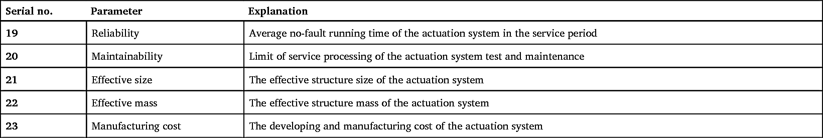
- 3. The type of steering engine depends on the control response and load power of rudder system, and related to the comprehensive using of missile-borne auxiliary energy source, if anti-manoeuvring occurs or not during the flight, and the steering cabin structure space to a great extent. Normally, the hydraulic steering engine is the preferred type of high-response, high-power system – the American Patriot, Hawke and Sea Sparrow all use this kind of steering engine. If we consider the comprehensive use of a missile-borne auxiliary energy source, the missile mass can be reduced effectively. In addition, flight test practice proved that if a cool gas steering engine is used, control plane anti-manoeuvring must be absolutely avoided during flight. Whether the structure including actuating cylinder, servo valve and feedback potentiometer in rudder twisting structure is whole or bulk, normally depends on the shape and size of structure space that the steering engine cabin can provide.
- 4. The type of control mechanism is the same as the type of steering engine structure, and mainly depends on the structure space provided by the steering engine cabin. Normally, the linear feedback structure of the integral steering engine matching to a push-pull linkage mechanism is mounted in a large hollow cylindrical structure space (such as in the Sam 2 and 3). The angle feedback structure of a decentralized steering engine matching to a push-push lever mechanism is mounted in a small hollow cylindrical structure space (such as in the Sea Sparrow or Aspide). For a ring column structure space with a middle solid (where an engine long nozzle is mounted), an integral steering engine push-pull mechanism is mounted (such as in the Sea Dart), and a decentralized steering engine push-push mechanism (such as in the Patriot) according to tradition and requirement. Because of the limitation of effective space, the installation of pitch and yaw control mechanisms is antisymmetric to integral steering engine. Therefore, two guidance control systems are symmetric; one of the polarity of the steering engine must be changed to keep the polarity of the two control planes coordinated. Whatever mechanical differential or electric differential is used by the rudder system, it can cross-match with the integral or decentralized steering engine.
-
Table 5.10
Additional conditions of design of control actuation system of anti-aircraft missile Division Serial no. Parameter Explanation Control trajectory 1 Change regulation of control plane deflection Typical change of control plane deflection of control trajectory 2 Change regulation of control plane moment Typical change of control plane moment of control trajectory 3 Change regulation of locking moment Typical change of locking moment of control trajectory 4 Energy inter stage switching time The switching time of energy I, II stage Frequency coupling 5 Bending and torsion frequency ratio of control actuation system Bending and torsion natural vibration frequency ratio of control plane actuation mechanism 6 The frequency ratio of mechanism natural vibration and energy characteristic frequency Torsion natural vibration frequency and energy characteristic frequency ratio of control plane actuation mechanism Emission control system 7 Energy start time The time from energy starting to establishing pressure Telemetering system 8 Output signal of comprehensive amplifier of rudder system Corresponding telemetry attachment is adopted 9 Control plane moment Corresponding telemetry sensors and their amplifiers are used 10 Control plane deflection Corresponding telemetry sensors or attachments 11 energy characteristic parameter Such as the pressure of gas, fluid energy source, flow, temperature, vibration, current, voltage or frequency of power supply 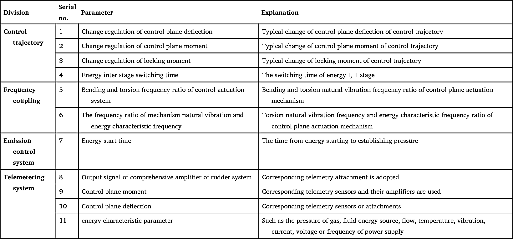
- 5. Is the steering engine energy of control actuation system common source or division source with seeker antenna energy? Is it comprehensively used with other missile-borne auxiliary energy or supplied independently? From the view of reducing mass, decreasing volume and economic rationality design, if the condition is allowable, in the condition that does not affect the operating performance of energy users, one should try to adopt a common source scheme and missile-borne auxiliary energy comprehensive utilization.
- 6. The deflection speed of the control plane depends on control instructions and the transient variation rate of a steady signal and speed load characteristic of the steering engine. The former is related to the design of control trajectory; the latter is the inherent characteristic of the selected steering engine. The deflection speed of control plane, usually associated with aerodynamic configurations of missiles, is low for canard (such as the Sidewinder), moderate for normal rudder (such as the Sam 2) and tail vane (such as the Patriot), and relatively high for full motion missile wing (such as the Sea Sparrow and Aspide). Actually, for linearized missile control bodies, the first thing is to limit the missile’s roll angle, which requires the aileron steering engine of the rolling loop to have a higher speed. The steering engine of the pitch and yaw loops also needs to have the proper speed in order to ensure the manoeuvre overload change rate of missile. Usually the latter is lower than the former. If the electric differential scheme is adopted and the independent aileron rudder is to be adopted, the yaw speed can also be satisfied when the pitching speed of the steering engine is ensured. The problem is that the load speed should be allowed to fall considerably compared with the no-load speed; for example, even in the steering engine of the Patriot, its load speed is only about one-seventh that of the no-load speed. Certainly for special requirements, the yaw speed cannot be arbitrarily reduced.
- 7. The load moment of the control plane (including the rudder and aileron) depends on the maximum flying speed pressure in control trajectory, missile aerodynamic configuration, the maximum attack angle of missile and the maximum comprehensive deflection angle of the control plane. The maximum flying speed pressure is determined by the maximum flight Maher number and the minimum flight height. Missile aerodynamic configuration directly determines equivalent area of control plane and shaft position (that is, the action arm of force of the pneumatic pressure centre and the rotating shaft). The maximum attack angle and the maximum comprehensive deflection angle are determined by the maximum allowable overload of the missile. In order to reduce the hinge moment of the control plane, one should try not to adopt the full motion missile wing; the ‘combined canard rudder’ (such as the Sidewinder) is preferred, or allowance for larger anti-manipulation (such as the Patriot). The ‘combined canard rudder’ not only has a small equivalent area, but also its aerodynamic pressure centre varies very little with the missile’s speed, and therefore the hinge moment of rudder is very small. For a hydraulic steering engine and electric steering engine with strong anti-anti-manoeuvring capability, larger anti-manoeuvring moment is allowed – that is, changing the polarity and size of the arm of force, trying to reduce the maximum positive control moment. Taking the Patriot as an example, the ratio of positive to negative control moment is about 5:4, as shown in Fig. 5.8.
- 8. Comprehensive deflection angle of control plane (including rudder and aileron) depends on the maximum allowable rudder deflection angle and equivalent maximum aileron deflection angle. The former is limited by the maximum allowable overload of control trajectory; the latter is determined by the maximum allowable disturbance of the rolling loop. Whether a mechanical or electrical differential is used, and whether a push-pull steering engine or push-push steering engine is used, the comprehensive deflection angle of control plane cannot be too large. It is normally 20–30°, and in particular the maximum comprehensive deflection angle of full motion missile wing is not over 22°. The other aerodynamic configurations rarely exceed 35°. If these angles are otherwise, the missile will easily go out of control, as aerodynamic drag increases. This will also increase the nonlinearity and asymmetry of the control mechanism, and make the location of the parts of the mechanism more difficult to arrange.
- 9. Indexes such as mass, volume, reliability and costs of control actuation systems have a significant effect on the overall performance of anti-aircraft missile control systems. Therefore, when the overall design of the control actuation system is conducted, these indexes must be fully demonstrated, through comprehensive analysis and comprehensive comparison. A quality optimization working belt of a control actuation system taking time as abscissa, mass as ordinate, power as reference index, load cycle percentage as condition, is shown in Fig. 5.9. The same optimization working belt of volume, reliability and costs can be obtained. Using the method of superposition to find out the intersection of the above index of optimization working belts, and considering the ability of anti-anti-manoeuvring and comprehensive utilization of missile-borne auxiliary energy and other special factors, ultimately, the basic types of control actuation system of the best or the second best are identified.
- 10. The relative standards of comprehensive evaluation of the control actuation system are: complexity, reliability, maintainability, costs, characteristics and development potential. Usually the greatest concern is relative performance. Systems with good technical performance tend to be complex and involve low reliability and high costs, but the effect on mass and volume is not obvious. This is because mass and volume mainly depend on system structure, design technique, structure material and the manufacturing process. Reliability and costs are not sensitive to volume or mass; they are functions of the complexity and number of components, and related to maintainability. Therefore, comprehensive thinking shall be considered in thorough evaluation of the control actuation system.
-
Figure 5.9 Optimum working zone of control actuation system mass (one-third load circle)A – Gas execution system (solid gas generator size according to 100% load cycle) and cold air execution system; B – Pressurized discharge hydraulic actuating system of gas and cold gas; C – Circulating hydraulic actuating system of gas turbine pump; D – Circulating hydraulic actuating system of battery motor pump; E – Circulating hydraulic actuating system of gas motor pump (Comprehensive utilization of energy).
5.4.3. Design guidelines
1. Rudder system
- 1. Rudder system bandwidth. The rudder system is essentially a low pass filter. To ensure a certain bandwidth of the rudder system, as far as possible one should not use unlimited increase comprehensive amplification gain, the speed of the steering engine and increase the transmission ratio of the control mechanism to solve bandwidth problem. Because this makes the system unstable and the energy power becomes large, the equivalent arm of force becomes too small. The inertia feedback network can be considered to solve the problem.
- 2. Electrical differential synchronization. Since the two rudder systems are not synchronized, the rudder aileron system will inevitably cause an additional effect, known as the additional aileron effect or rudder effect. This kind of additional effect is usually relatively small, and as the control plane synthesis deviation angle has a certain margin and the rudder loop will not be blocked, it is not a big problem. If the additional effect is relatively large, and the margin of synthesis deviation angle is small, then the rudder loop may be blocked. In order to improve the asynchrony of the two rudder systems due to electrical differential, some technical measures such as characteristic selection, slope adjustment and sum difference cross feedback of the rudder system can be used in rudder system design.
- 3. Electric zero position lock. For a rudder system using a nulling signal as control plane lock, its condition are: rudder system is in its normal working condition; stall moment must be greater than the maximum locking moment; positioning accuracy is quite high; and invalid stroke is small enough. Only in this way can the control plane be reliably and accurately locked in the zero position.
- 4. Anti-anti-manoeuvring capability. To reduce the aerodynamic moment of the control plane, the modern anti-aircraft missile will operate in the anti-manoeuvring state, so the rudder system must have anti-anti-manoeuvring capability. The key here is to select the appropriate steering engine system; a hydraulic steering engine is preferable. Flight tests show that for the anti-aircraft missile with the axis position of control plane using compensation or over compensation aerodynamic configuration, in subsonic and transonic flight, the control plane is in anti-manoeuvring state, the rudder system of the air cooling steering engine is out of control and divergent, but the rudder system of the hydraulic steering engine can still work properly.
2. Steering engine
- 1. Steering engine bandwidth. Determined by the bandwidth allocation of the rudder system, this should be compressed as much as possible. Development practice proves that excessive bandwidth will inevitably require the increase of the steering engine speed gain; thereby, the steering engine and its energy power are obviously increased. Too wide bandwidth is susceptible to electronic noise and other interference, and even the self-excited oscillation of the control plane may result in system instability under some incentives.
- 2. Steering engine speed. This mainly depends on the steering engine bandwidth and the equivalent arm of force of the mechanism. For control plane anti-manoeuvre, missile static instability control and other special circumstances, the steering engine requires a larger load speed, and deep negative feedback in the rudder loop of control plane and damping circuit, respectively. Under normal circumstances, the speed of the steering engine should not be too large, so as to ensure the stability of the system, reduce the energy power and obtain the appropriate mechanism equivalent arm of force.
- 3. Steering engine moment. This should be able to overcome the composite load moment such as hinge moment, inertia moment, damping moment and friction moment of the control plane, and provide a certain control plane speed under the action of the rated load moment. Even with the maximum hinge moment, the steering engine should maintain a minimum control plane speed for reliable work.
- 4. Load characteristic analysis. Fig. 5.10 shows the load characteristic curve of the control plane of a typical full motion missile wing type aerodynamic configuration anti-aircraft missile. This is mainly characterized by an elastic load. The trajectory of the speed-moment characteristic curve is rotating, the axis being slightly inclined, with a slightly distorted malposition ellipse; the arrow direction indicates the main characteristics of the load. For most anti-aircraft missiles controlled by an air rudder, the stiffness (hinge moment) plays a leading role, and the arrow direction is clockwise. For a very small number of anti-aircraft missiles controlled by thrust vectoring, the inertia (rotary inertia) is dominant, and the arrow direction is counterclockwise. The corresponding power curve shows a ∞-shaped cross rotation in four quadrants.
- 5. Steering engine output characteristics. Regardless of the type of steering engine, the output characteristic curve must include the load characteristics. Taking the hydraulic steering engine as an example, according to the principle of maximum power point of view, the matching situation is shown in Fig. 5.11. It can be seen from the diagram that the characteristic curve of the steering engine just contains the load curve. The characteristic curve of the steering engine and the load curve are tangent at the maximum power point, and the two states of positive and negative manipulation (or resisting and help moment) have a good matching relation.
3. Control mechanism
- 1. Dynamic characteristics of control mechanism. Similar to the oscillation link, it is essentially a quasi-elastic system with certain stiffness, inertia, damping, friction and active gap. Its typical frequency characteristics are shown in Fig. 5.12b. The control mechanism of the control plane should have proper natural frequency and structural damping, smaller friction and movable clearance. It not only satisfies the bandwidth of the rudder system, but also prevents the flutter of the control plane. It is proved by practice that too-low natural frequencies of the control mechanism can damage the control mechanism due to structural resonance and excessive amplitude when the frequency characteristic of the rudder system is tested.
- 2. Static characteristics of control mechanism. It is required that the deviation angle of the control plane is linearly transmission-related to the travel of the steering engine to satisfy the straightness of the rudder system and symmetry requirements of the aileron differential. The typical transmission characteristics shown in Fig. 5.12a are mainly guaranteed by the design. The transmission ratio is the characteristic parameter of the control mechanism, and it depends on the equivalent force arm of the mechanism. The equivalent force arm can adjust the transmission ratio of the control mechanism, and change the distribution relation between the moment and the speed. Once the equivalent force arm is determined, the transmission and transformation relationship between the steering engine stroke and the control plane deviation angle, the steering engine thrust and the control plane control moment, the steering engine speed and the control plane speed are also determined. Therefore, it is the most important parameter of the control mechanism, and the optimum transmission ratio can be obtained only by careful design.
- 3. Frequency range of control mechanism. The control mechanism has dual functions of motion conversion and power transmission. Its design, in addition to the design specification of strength and stiffness, is mainly according to the frequency specification. It meets the dynamic characteristics of the control plane control mechanism, ensures the rudder system bandwidth, prevents resonance damage of the rudder control structure and avoids possible aeroelastic problems from happening during rudder manipulation. If the torsion stiffness of rudder control is not sufficient, it causes static divergence in anti-manipulation conditions; twist bend frequency coupling of rudder control causes flutter in the aerodynamic and energy coupling conditions.
- 4. Installation adjustment and clearance of feedback mechanism. The feedback mechanism is only used in the decentralized steering engine, and the gear mechanism or linkage mechanism is often used. The deviation angle of the control plane is transmitted to the feedback potentiometer of the steering engine by a certain amplification factor, so that the loop of the rudder system is closed. The feedback mechanism needs to be installed with the correct polarity, sufficient linearity and symmetry, easy precision adjustment (such as centre distance of gear pair, rod length of linkage, potentiometer shaft can be adjusted continuously), inspection and reliable locking. For the connection of the mechanism and the installation of the potentiometer, particular attention should be paid to the overall dynamic stiffness and vibration resistance of the assembly, and various technical measures (such as the two piece gear with ring type torsion spring, gear with hairspring torsion spring, and compensating spherical hinge) should be adopted to eliminate the clearance of the mechanism and ensure the stability of the rudder system.
- 5. Setting and type of lock mechanism. The lock mechanism is used for a certain period of time, such as the process of missile storage until before the launch, or before starting control, or before the separation of the first and second stage of the two-stage missile. It reliably locks the control plane that does not work temporarily, and can be equally reliably unlocked when needed. In general, when the electric lock accuracy of the zeroing line of the rudder system is limited due to the zero error of the rudder system and the working gap or the working state of the energy, and cannot be used, a special control plane locking mechanism must be adopted. The control plane locking mechanism of the two-stage missile must ensure that it should be locked reliably in the first stage flight at the maximum hinge moment. When it is separated, it must be reliably unlocked at the corresponding hinge moment. History has shown us that if the locking moment is not enough, the control plane will be unlocked ahead of time, and eventually lead to a breakup of the missile in the air.

4. Control plane
- 1. Rotary inertia of control plane. In order to ensure that the rudder system has enough bandwidth, to prevent structural resonance damage caused by too-low natural frequencies of rudder control mechanism, if increasing the stiffness of control mechanism, and meanwhile increasing the mass of control mechanism, the simple and effective method is to reduce the rotational inertia of the control plane by changing material or the form of section and improve the natural frequency of the rudder control mechanism without changing the aerodynamic shape of the control plane.
- 2. Balance or overbalance of the control plane. In order to prevent the rudder mechanism dynamic flutter, in addition to changing the control plane or section geometry, structural material and mass distribution, the main method used is to install the right bob-weight in front of the control plane shaft, used to adjust the relative position of the centre of mass and rotating shaft so that the centre of mass is placed on the rotating shaft or in front of the rotating shaft in order to achieve balance or overbalance.
- 3. Compensation or over compensation of control plane. See above.
5. Energy
Energy source has a type that is available for control actuation systems only, also has type shared with the seeker antenna, even powering the entire missile power grid. Involving a wide range of complex content, there are many problems need to be discussed. The abstracts are listed below.
- 1. Ballistic function of energy design. Missile-borne energy is different from ground energy; its power and total work are limited. Therefore, missile-borne energy rated power, taking the control actuation system as an example, is not determined by the product of the maximum hinge moment that may occur in all control trajectories and the maximum rudder deflection speed; and its total work is not the product of this power and the longest flight time. The energy design is based on the control trajectory function, calculates the power spectrum and the total work time curve actual possible appearing, and thus determines the rated power and total energy.
- 2. Working condition research of control trajectory. For the control actuation system, the variation law of the yaw angle of the control plane, the curve of the angle speed of control plane and the hinge moment versus flight time are studied. For seeker antenna, the variation law of antenna declination angle, the curve of antenna swing angular velocity and inertia moment versus flight time are studied. For the entire missile power grid, the curve of current consumption, voltage and frequency versus flight time of all power supply subsystems are mainly studied. Thus, three sets of power spectrum and the total work time curve are obtained as the energy design basis of steering engine, antenna and entire missile power grid. If the missile auxiliary energy is comprehensive utilized, it needs to refit three sets of curves to obtain the total power spectrum and total work. In order to study the authenticity of missile typical working conditions and the adaptability of a control actuation system, a control test vehicle (CTV) has been launched.
- 3. Selection of constant power and variable power energy. The energy of the control actuation system must be matched with the working condition of control trajectory. The meaning of match usually refers to containment, coincidence, as a special case, is adaptation. Constant power energy and variable power energy correspond to containment and coincidence. In general, constant power sources are used mostly for small missiles, such as the gas actuation system of Chaparral and Sam 7; they are simple, widely applicable and low cost. For large missiles, variable power sources should be used preferentially in accordance with the change of working condition of trajectory, such as the Patriot’s battery electric variable pump hydraulic actuation system, the Sea Dart’s gas motor variable pump hydraulic actuation system or the Sea Sparrow’s nitrogen booster oil accumulator hydraulic actuation system. However, many large missiles are still using constant power energy, such as the Sam 2 and 6’s series cool gas actuation system and the Aspide’s gas turbine quantitative pump hydraulic actuation system. In addition to considering the working condition of trajectory and the percentage of the load cycle, it is also closely related to historical inheritance and design style.
- 4. Consideration of exhaust energy and cyclic energy. As far as we know, the gas energy, cooling air energy and electric power used by gas steering engines, cooling air steering engines and electric steering engines are all exhaust energy – one use, no recycling. The hydraulic energy used by the hydraulic steering engine is divided into non-cyclic (exhaust) type and cyclic type. The basic type of the former is a gas booster accumulator; the latter has different types such as a gas turbine quantitative pump with solid propellant, a gas motor variable pump with liquid unit agent (flow controllable) and a motor variable pump with chemical batteries according to different primary energy.
- 5. Isolation of interconnections of energy in common source and comprehensive utilization. In common source and comprehensive utilization, effective technical measures must be used to isolate interconnections. Aspide is a typical example of combined utilization of common source and missile-borne energy (Fig. 5.13). In order to prevent the hydraulic control actuation system from connecting to the antenna energy when it works at high flow rate, the isolation valve sets the limit at the source junction, limits the flow into the control actuation system and ensures a sufficient flow of seeker antenna energy. To prevent the idling hydraulic system from connecting to the turbine engine, a loading valve is arranged at the outlet of the hydraulic pump for regulation and isolation, repressing the flow entering into the hydraulic system, loading on pump, preventing the turbine from idling and over-rotating, ensuring that the engine speed, frequency and voltage do not exceed their limits. The damping disc (such as the Sea Sparrow’s gas turbine generator) and regulator (such as the Sam 6’s air-cooled turbo generator) can also be used to control the speed of the turbine generator.
- 6. Instantaneous supply method of ballistic peak power. When the motor is selected, how to obtain more instantaneous power? The gas pressurization accumulator can be adopted in the circulating hydraulic system. In the case of the instantaneous large rudder deflection speed, with a certain rate of pressure change, it can be converted into the additional flow of accumulator, and the instantaneous peak flow of missile trajectory can be supplied together with hydraulic pump. For example, in the Patriot hydraulic actuation system (Fig. 5.14), when the missile suddenly manoeuvres, the system load flow increases, the pressure drops steeply, and the pressure feedback makes the swash plate of the variable pump slant to the maximum position and provide the maximum flow. At the same time, the helium pressurized hydraulic accumulator quickly provides an instantaneous supplementary flow. For an electric actuator system with a clutch control drive motor, due to the existence of high power clutch and reduction gear, the flywheel effect can be used, at the moment of transient stall torque, with a certain rate of speed change, it can be converted into the additional moment of flywheel, and the instantaneous peak torque of the missile trajectory is provided with the motor – for example, the standard missile electric execution system.
5.4.4. Performance test
During the development of the control actuation system, many ground tests need to be done. Finally, the flight test is carried out and passed. The
performance test is designed to verify the design ideas and manufacturing quality, and to further perfect and improve the results through analysis. Taking the energy utilization of the two-stage missile gas turbine pump shown in Fig. 5.15 as an example, the main items of the corresponding performance tests are as shown in Fig. 5.16.

1. Frequency characteristic test and structural resonance test
The working state of the rudder system is excited by the sine wave of the steering engine. The amplitude, phase and frequency characteristics of the rudder system can be obtained if the signal before the amplifier is used as input and the rudder angle telemetering sensor is output. For the long drive chain push-pull linkage mechanism of integral steering engine, the feedback potentiometer is used as the input signal, and the rudder angle error telemetry sensor is used as the output signal. The amplitude, phase and frequency characteristics of the control mechanism can be obtained. If in the natural vibration point of control mechanism keeps resonance for a certain time, that is anti-structural resonance test of control mechanism. Both the mechanism and the support arm of the steering gear should be in good condition after vibration.


2. Simulated load test and anti-anti-manoeuvre test of the system
In the operating state of the rudder system, the steering engine is sinusoidally excited by a certain frequency and amplitude, and a load simulator is applied to the rudder to apply a linear or constant value load. The rudder deflection is required to be smooth without blocking, the waveform is not distorted and the phase shift is within a certain range. At the same time, the polarity of the load can be changed, the auxiliary torque is produced, and the anti-manoeuvring state is simulated. The anti-anti-manoeuvring capability of the rudder system is tested by using the characteristic parameters of sub subsonic and transonic trajectories. The requirements for the characteristics of a control system loop shall be met.
3. Vibration modal characteristic test of control actuation system
In the rudder control system with missile-borne hydraulic energy in working condition, the input signal to the integrated amplifier is zero and the rudder is clamped to zero. The rudder is excited by a wide band electromagnetic vibrator, and displacement or velocity is measured in each feature point of the rudder by a precision sensor. The natural frequencies and modes of each order of rudder are obtained, and the ratio of bending and torsional frequency determined to provide the basis of analysis of rudder flutter. At the same time, the frequency response characteristics of missile-borne energy high speed rotating components (such as turbine, electric generator and hydraulic pump) can be measured by vibration spectrum analysis.
4. Service life test
Service life, usually the total time of no-load test, shall meet the requirements of the test cycle of the guidance and control system. At this time, the rudder system is in operation, and the missile-borne energy is in the ground test state.
5. Energy connection test and electromagnetic compatibility test
The guidance and control systems are in the joint test status.
- 1. Isolation test of inter connections of energy. For missile-borne composite energy, simulating the transient no-load low pressure of hydraulic system, and checking the isolation and control function of the hydraulic loading valve; simulating the transient no-load large flow of the steering engine, and checking the isolation and control function of the hydraulic current limiting valve. When the transient interference is removed, the two valves’ isolation should be lifted in a short time.
- 2. EMC test between execution system and missile-borne electronic equipment. When all the on-board equipment is switched on, it is required that the electrical products of the system, such as electric discharge tube, electric igniter, turbo generator, electromagnetic spring lock hook, pressure relay, electromagnetic hydraulic switch, electrohydraulic servo value, linear potentiometer, integrated amplifier, etc. should be operated without the influence of the radio frequency interference of the missile-borne electronic equipment. Similarly, the work of electrical products in this system should not affect the normal work of missile-borne electronic equipment, especially the computer, strapdown inertial navigation unit seeker and electrical fuse.
6. Flight test
Flight tests associated with the control actuation system are flight tests of the missile in independent loop state and closed loop state. Independent open loop is that the damping loop and the acceleration loop are in a state of disconnection, because there is no damping stability and acceleration feedback, the trajectory varies drastically, to control execution system, from the hinge moment and rudder deflection speed, are the most serious condition. For the independent closed loop, because of the damping stability and the acceleration feedback, the trajectory is changed slowly, and the change of the ballistic condition is also slow. The closed loop means that the missile guidance loop is in a closed state, and the closest state of combat with the actual combat is the telemetry state of combat, aiming to study the missile warhead coordination. The independent loops mainly examine the actuation system of signal response, power driving characteristics, anti-anti-manoeuvring capability and adaptability of ballistic trajectory condition of corresponding energy. At the same time, the correctness of the associated emission control and flight control sequence is further verified. The closed loop mainly inspects the EMC capability of the system, the ability to isolate the power supply, and the reliability of the control actuation system under the real climate and mechanical environment in complex flight and electronic environments.
5.4.5. Conclusions
1. Control actuation system
The control actuation system has been combined with digital autopilot and strapdown inertial navigation unit (controlled by an on-board computer). The main rudder system is still the position servo system, to the development of suitable for digital control. Most of the rudder system can work under the anti-manoeuvring state of the control plane, and the speed requirement of the steering engine is also properly reduced. The types of steering engine are still diverse and traditional. The large missile uses mostly a hydraulic steering engine, followed by an air-cooling steering engine. Small missiles use gas steering engines and electric steering engines simultaneously. Because of the convenience, no leakage and meet the requirements of unitized missile-borne energy, the electric steering engine has been developed from small missiles to large missiles, especially shipboard air defence missiles. Most of the control plane differential schemes are electro differential, and mechanical differential is seldom used. The United States mostly use the hydraulic steering engine, Russia adopts the air-cooling
steering engine and France employs the electric steering engine. One way of power supply is that individual energy is provided to the control actuation system, and the other way is comprehensive utilization of missile-borne auxiliary energy by full missile.
2. Control ballistic condition
In order to make the system and its energy design economical and reasonable, it is necessary to make a comprehensive study of the operating conditions of the system from the two aspects of the control signal flow and the energy power flow. Its contents mainly include: the law of movement of control plane deflection angle and the law of change of corresponding load moment; the dynamic characteristics and aerodynamic characteristics of the actuation system; the law of the antenna angle variation of the seeker and the corresponding load moment change law; the law of load current, frequency and voltage change with trajectory of the missile-borne power network. All of these parameters are functions of controlling trajectory, so a comprehensive study involving collectivity, guidance, control, aerodynamic, load, aeroelasticity and structure, etc., relevant professions, only strong coordination and close cooperation can be effective. Numerical simulation can be used to study the working conditions, and can be combined with missile test when necessary.
3. Overall demonstration and system analysis
The proof of the overall scheme of missile is an important premise to the technical feasibility analysis of the actuation system. The technical feasibility analysis of the actuation system is a reliable guarantee for the implementation of the overall technical requirements of the missile. Both should work together and participate in the cross, which will allow the system to put forward ‘counter demands’ and ‘counter suggestions’ to the whole, and also allow the overall revision of the requirements, and put forward technical research projects to the system. Only by combining organically and implementing feedback control method can the best and most applicable system programme be obtained.
5.5. Auxiliary power unit of anti-aircraft missile
Combined with the design method of an anti-aircraft missile control actuation system, the anti-aircraft missile-borne auxiliary energy and classification methods of its primary energy are discussed, and typical examples
are analysed. A series of important issues of missile energy unit and multiple, separate and comprehensive utilization, separate source and common source, constant power and variable power, quantitative pump and variable pump, exhaust type and cyclic type, primary energy types are discussed, and we obtain key points of scheme selection and prediction of missile-borne auxiliary energy sources.
With the development of anti-aircraft missile, the requirements of miniaturization and handiness of missile-borne equipment become higher and higher. As far as missile-borne electronic equipment is concerned, due to the smaller control power needed by electronic components, the problem is relatively easy to solve. As for the auxiliary energy of missile, due to the large drive power of the gas, hydraulic and mechanical equipment, it is difficult to solve the problems of heat, strength and material. The solution is to strengthen the research of ballistic condition, put forward practical energy requirements, the key lies in how to make reasonable allocation and comprehensive utilization of the missile auxiliary energy scheme to give the scheme the best characteristics.
Generally speaking, the missile-borne missile energy should include two major parts: primary energy (power plant propellant) and auxiliary energy (full missile power supply, energy sources for guidance and control systems, and booster energy of delivery system of power plant propellant). In this section, the configuration and comprehensive utilization of the missile-borne auxiliary energy scheme are discussed.
5.5.1. Classification of power scheme
1. Comprehensive utilization of energy in delivery systems of power plant propellant and executive systems
- 1. Cold air source. It is used to boost liquid rocket engine propellant tanks and to supply air to the air-cooled steering engine of control actuation system. An example is the Russian Sam 2 ground-to-air missile series, as shown in Fig. 5.17.
- 2. Gas source. The gas generated by the liquid unit is decompressed, pressurizing the flexible plastic bag of the fuel tank of the ramjet engine, at the same time drives gas motor hydraulic pump to supply oil for hydraulic steering engine. An example is the British Sea Dart ship-to-air missile, as shown in Fig. 5.18.
- 3. Ram air source. Going through ram turbine, the high-speed ramjet air from the ramjet intake port drives the fuel pump and hydraulic pump at the same time. The fuel is supplied to the ramjet engine, and the hydraulic steering engine is supplied with hydraulic fluid. They are commonly used in some coastal defence or anti-aircraft missiles using ramjet engines as a power plant, as shown in Fig. 5.19.

2. Comprehensive utilization of power and execution system energy
- 1. DC power supply. With a missile battery, the power supply is not only to the electrical equipment, but also to the electric steering engine. Examples are the Tail Thorn, Standard, Sidewinder and other anti-aircraft missiles, as shown in Fig. 5.20.
- 2. AC power supply. The turbine generator can be classified according to its working substance and driving object:
-
- a. The gas turbine simultaneously drives the alternator and the hydraulic pump, such as Aspide army general air defence missile, as shown in Fig. 5.21.
- b. Air cooled turbine drives alternator, cooled air supplies air to the steering engine too. Examples are the Russian Sam 3 and 6 ground-to-air missiles, as shown in Fig. 5.22.
- c. Ram air turbine drives the fuel delivery pump, and also drives the AC generator and hydraulic pump after increasing speed. They are commonly used in some coast defence or anti-aircraft missiles using ramjet engines as a power plant, as shown in Fig. 5.19.

3. Configuration forms of missile-borne auxiliary energy sources
There are two basic configurations of missile-borne energy: common source and separate source. The common source is usually closely related to comprehensive utilization, and each separate source has its specific conditions. It is described according to different energy types.
- 1. Hydraulic sources. The seeker antenna and autopilot steering engine are common sources in Aspide, but are separate sources in American Sparrow series missiles. The seeker antenna energy uses solid propellant gas pressurization piston hydraulic oil storage device, and the pilot steering engine is pressurized with high pressure nitrogen gas and has a capsule type hydraulic accumulator with a gas pressure reducer, as shown in Fig. 5.23.
- 2. Gas sources. For American Chaparral ground-to-air missiles, the gas that drives the gas turbine and the gas supplied to the gas steering engine are common sources (Fig. 5.24). However, for the Sparrow series, the gas that drives the turbo generator and the gas for the booster of hydraulic energy of seeker antenna are separate sources (Fig. 5.23).
- 3. Cooled air sources. The cooled air turbo generator used by the Sam 3 and 6 and the cooled air steering engine are common sources (Fig. 5.22). This separate source is very rare on anti-aircraft missiles.
- 4. Electric sources. The French Sidewinder uses common sources; the missile battery supplies power to the whole missile electrical equipment including the electrical steering engine (Fig. 5.20). However, for the American Patriot missile, it is separate sources (Fig. 5.25) – that is, the special battery supplies power to the electric variable pump separately.
- 5. Unit agent. For the Sea Dart, fuel gas of melting pressure for the fuel tank of a ramjet engine and fuel gas for the actuation system gas motor hydraulic pump driving are common sources; all are unit agent Isopropyl nitrate (I.P.N.) (Fig. 5.18). However, for the Sam 2 series, fuel gas produced by unit agent I.P.N. is specially designed to drive propellant delivery pumps for liquid rocket engines; it is not used pre-pump pressurizing to the propellant storage tank (Fig. 5.17).
4. Classification of missile-borne auxiliary energy sources and their primary energy sources
1. Classification by auxiliary energy working medium element
- 1. Diversified auxiliary energy. For example, the Patriot is separate sources, electricity, gas and liquid three types; the Aspide is fuel, electricity and liquid three types, common sources; the Chaparral is fuel and electricity two types, common sources; the Sam 3 and 6 are gas and electricity two types, common sources.
- 2. Single auxiliary energy. For example, the French Sidewinder and American Standard are single type, common sources.
2. Classification by primary energy sources working medium used by electrohydraulic energy
- 1. The gas generated by a solid gas generator serves as primary energy source. For example, gas turbine engine, gas booster accumulator for the Sparrow series; gas turbine driven engine-hydraulic pump for the Aspide.
- 2. The gas generated by liquid gas generator is used as primary energy source. For example, gas turbine propellant delivery pump for the Sam 2 series; gas motor hydraulic pump for the Sea Dart.
- 3. High pressure cooled air is used as primary energy source. For example, cooled air turbine generator for the Sam 3 and 6; high pressure nitrogen pressurization accumulator for the Sparrow series.
- 4. Ram air is used as primary energy source. For example, impulse turbine drive alternator- fuel delivery pump for some types.
- 5. A battery is used as the primary energy source. DC motor drive pressure compensated the variable hydraulic pump for the Patriot.
5.5.2. Application examples
1. Basic principle
- 1. The integration of missile-borne auxiliary energy and main energy (power plant propellant), and internal of missile-borne auxiliary energy must be integrated and considered on the premise of meeting the overall performance index of missiles. This is a prerequisite for determining the type of missile-borne auxiliary energy sources.
- 2. From the view of reducing the mass, reducing the volume, compressing the type of energy, convenient operation and use, making the design more economical and reasonable, if the performance of the related subsystems (energy users) is not affected, the integrated utilization of the missile-borne auxiliary energy and the common source should be used as much as possible. This is the basis for the selection of the missile auxiliary energy scheme.
- 3. In the presence of the influence of correlated connection in the related subsystems (energy users), the missile auxiliary energy must adopt effective technical measures to remove the connection or improve the connection condition, thus creating the conditions for the realization of the comprehensive utilization and the common source.
- 4. If there are special requirements and restrictions (including non-technical factors), the missile auxiliary energy can only be considered separately, and the separate source scheme is adopted.
2. Development of technology of missile-borne auxiliary energy from the evolution from Sparrow series to Aspide
In the Sparrow series missile-borne auxiliary energy, power supply (gas turbine generator), seeker antenna hydraulic source (gas booster piston accumulator), and pilot steering engine hydraulic source (nitrogen pressurization capsule accumulator) three sources are separated, as shown in Fig. 5.24. The advantages of such self-contained energy sources are: all energy sources are completely independent, without interference, and there is no mutual connection between energy sources; power and working condition match to the best condition; it is convenient to check before assembly; the pipeline loss is small; energy is self-contained; and reliability is guaranteed by components. Its drawbacks are that: the components bring their own energy, resulting in repeated settings; the mass, volume and cost are not economic; the power between the energy sources of each subsystem cannot be adjusted to each other; and the structure layout is not reasonable.
In Aspide missile-borne auxiliary energy, the primary energy of missile power (gas turbine generator and loading valve), pilot steering engine hydraulic source (gas turbine hydraulic pump and restrictor valve) and seeker antenna hydraulic source (gas turbine pump and pressure reducing valve) are all solid propellant gas turbine. The three sources are combined and comprehensively utilized, as shown in Fig. 5.21. The advantages of this type of combined energy are: the mass, volume and cost are economic; the power between the energy sources of each subsystem can be adjusted to
each other at a certain level; and the structure layout is reasonable. Its drawbacks are: sub system energy is not independent because of the common primary source; mutual interference is easy to occur among energy sources, having connection problem; and isolation measures must be adopted to make the system composition more complex and to some extent affect reliability. In addition, the power and operating conditions are not easy to achieve the best match; it is not convenient to check before assembly; and the pipeline loss is large. The main reasons why Aspide missile-borne auxiliary energy does not adopt its old prototype Sparrow series separate source exhaust type old system but adopts a new system of common source and recycling type are as follows.
- 1. Requirements of task. This mainly refers to the growth of flying time; compared to the Sparrow series, the solid rocket engine of the Aspide is lengthened, and its thrust increases accordingly. Considering the initial velocity of the carrier, the maximum operating time of missile is 60 s. From the view of the best working band of missile-borne energy, it is more reasonable to adopt the pump hydraulic circulation system than the extrusion hydraulic exhaust system.
- 2. Realistic possibility. Designers of the Aspide energy system firmly grasp the comprehensive utilization of missile-borne auxiliary energy and miniaturization of missile-borne equipment, on the basis of the original gas generator, gas turbine, alternator, and gas booster accumulator etc. technology of the Sparrow series, make the combustion, electricity, liquid and machine organically combined, develop a centralized and unified miniature electrohydraulic energy combination, together with other small, delicate hydraulic accessories, not only saves space, but also its mass is less than that of independent dispersion.
- 3. Performance guarantee. In order to improve the connection condition and ensure the respective performance, some isolation measures should be taken to the connection between three subsystems. The main measures are as follows.
-
- a. To prevent the influence of connection of no-load of hydraulic pump on over rotating of generator, a loading valve (or called repressor valve) is arranged at the outlet of the hydraulic pump for regulation and isolation, using the pump outlet pressure feedback to reduce the opening of the load valve, repressing the flow of fluid into the hydraulic system; the pump is loaded by throttling and boosting, to avoid the turbine no-load fast rotation, and ensure that the generator speed, frequency and voltage are not overrun.
- b. In order to prevent the connection influence of the pilot hydraulic steering engine working at a high flow rate on the follow-up speed of seeker antenna hydraulic servo system, at the junction of the hydraulic system and the branch, a flow limiting valve is set up for regulation and isolation. The pressure difference negative feedback is used to reduce the opening of the flow-limiting valve, to limit the flow into the steering engine, and to ensure the follow-up speed of the seeker antenna so as to search or track the target rapidly.
3. Application of liquid unit agent in Sam 2 and Sea Dart
The Sam 2 series liquid unit agent (Isopropyl nitrate), as a special auxiliary energy source for liquid rocket engine propellant delivery system (requirements of low pressure and mass flow), the gas generated from the storage tank decomposed by a liquid gas generator drives turbine, driving oxidizer pump and combustion agent pump coaxially, providing propellant to a combustion chamber of a liquid rocket engine. The starter of the turbine is the powder starting cylinder. It is a small, short working solid charge gas generator.
The gas produced by the decomposition of Sea Dart liquid unit agent (I.P.N.) serves as the primary energy and is shared by two systems, as shown in Fig. 5.19. One way of energy source goes to the hydraulic steering gear system of automatic pilot, another way pressurizes the ramjet fuel tank by a decompressor. The main object of supply is the former, in Fig. 5.19, gas motor hydraulic pump supplies oil to hydraulic steering engine (requirements of high pressure and small flow). The linear reciprocating motor pump is essentially a gas pressurization hydraulic accumulator, taking a stroke as a cycle, controlled by a gas hydraulic linkage distributing valve, with gas pressure compensation, continuous operation and variable flow output. It has a series of advantages such as high efficiency, quick response (low inertia, good acceleration), reliable (no rotating parts) and short starting time. A differential piston type reservoir is also available, used as booster oil supply before pump for hydraulic motor hydraulic pump to prevent cavitation, and also used as volume compensation and temperature compensation for system leaks. It is essentially, a self-pressurization tank with dual compensation capability. This auxiliary energy system adopts a common source system of control actuation system and power transmission system. Its main features are as follows.
- 1. Variable flow output with the change of ballistic condition. Mainly through the gas pressure feedback, the flow control valve automatically adjusts the flow of liquid unit agent (I.P.N.) to match with ballistic condition changes.
- 2. The whole system needs little power, low consumption of oil and low temperature rise of the system. As the variable flow output of the primary energy matching ballistic conditions, there is no heating oil temperature rise due to the constant flow output required by overflow valve bypass overflow. The actual oil volume is only 355 mL, and the maximum power range is 80 km.
- 3. In the primary energy devices complex, the use of a unit agent is inconvenient and the system has many drawbacks. When making specific choices, one must fully consider the working conditions and trajectory control measures and comprehensive utilization of energy and other aspects.
4. Method for regulating and controlling missile-borne turbine generators
The advantage of using a turbo generator as power source is its large power mass ratio, convenience of testing and checking, and easy realization of comprehensive utilization of missile-borne auxiliary energy and common source scheme. In order to ensure the stable frequency and voltage output of an AC generator, the turbine speed must be limited.
- 1. A hydraulic loading valve (stop valve) is arranged in the hydraulic pump system of the coaxial drive of the generator to avoid the connection influence of the no-load of the hydraulic pump on the over rotating of the generator. An example is the Italian Aspide gas turbine generator.
- 2. The eddy current damping plate is arranged in the generator, and the rotation speed is stabilized by using eddy current damping is proportional to rotating speed. An example is the American Sparrow gas turbine generator.
- 3. A centrifugal governor is arranged in the generator, and the air intake is controlled by the relationship between the centrifugal throttling and the speed of rotation to stabilize the speed.
5. Key points of missile-borne auxiliary energy scheme selection
- 1. Unit and pluralism. The rigidity of the cooled air energy is poor, the structure size of the gas cylinder is large and the environmental temperature effect is great. While the hydraulic energy has good rigidity, large power and hard control characteristics, but the equipment is complicated, the energy is diversified, and the maintenance is inconvenient. As for the power supply, the international experts believe that the relative performance (especially reliability) of the battery-driven missile control plane is higher than that of the hydraulic pneumatic system. Therefore, from the view of tactical use and maintenance and reliability, it is better to adopt unit missile-borne auxiliary energy. The only solution is the missile-borne hot battery or high efficiency battery, such as the US Standard ship-to-air missile, Stinger portable air defence missile and French Sidewinder field air defence missiles, are powered by a missile-borne battery and provides power to the on-board electrical equipment, including the electric steering engine. Of course, from the tactical technical performance and comprehensive utilization point of view, if another working medium steering engine must be employed, regardless of the cooled air, gas and hydraulic steering engine it is a diversified range of missile-borne auxiliary energy category.
- 2. Individual setting and comprehensive utilization. The premise is the missile power stack, control execution and power supply scheme and its combination form. Only when a liquid rocket engine or a ramjet engine is adopted is it possible to consider the combined use of the auxiliary energy of the control system and the power delivery system. Only when the use of non-motorized steering engine or primary energy uses gas (gas or cooled air), at the same time, when the turbine generator is used as missile energy, it is possible to consider comprehensive utilization of the control actuation system and the full missile power supply. A typical example of maximizing the comprehensive utilization of auxiliary energy is the early British ship-to-air missile Sea Cucumber, using gas produced by liquid unit agent isopropyl acetate (I.P.N.). Both pressurize the liquid rocket engine two propellant tank, but also drive the turbine and drive the propellant delivery pump, control actuation system hydraulic pump and AC generator. On the other hand, if a solid rocket motor scheme is adopted, there is no problem of the comprehensive utilization system of auxiliary energy power transmission system, if in order to avoid energy performance linkage, electromagnetic interference and structural restriction between subsystems, the scheme that the auxiliary energy is set separately is adopted. Two typical examples in this respect are as follows.
-
- a. Two separate batteries are the power supply of the electric variable hydraulic pump and the missile (alternating current is supplied by an alternating current machine) in American BOMARC.
- b. The gas generated by two independent solid charge generators, respectively, drives the turbo generator supplies power to the missile, and drives the booster hydraulic accumulator to supply oil to seeker antenna in the American Sparrow.
- 3. Gains and losses of comprehensive utilization. In the analysis of advantages and disadvantages about the comprehensive utilization of auxiliary energy, it is necessary to consider not only the positive effect, but also the negative impact. Take the gas turbine electro hydraulic energy solution as an example; the positive effect is obvious, while the negative influence is often neglected. These possible negative effects are as follows:
-
- a. The connection between the power supply and the hydraulic circuit, the common hydraulic circuit, and the complex improvement measures taken for this purpose, to some extent, affects its relative reliability.
- b. Between the power supply and the hydraulic circuit, common source hydraulic circuit, and the individual improvement of each circuit and the ‘contradiction’ of test maintenance. Cross coordination for this purpose tends to make the versatility normal.
- c. The influence of the changing of back pressure of the gas turbine exhaust jet with the missile height and angle of attack will cause a considerable change in the energy output power and the generator frequency. This limits the applicability to some extent.
- 4. Divided source and common source. The divided source refers to the system of self-contained energy, same as individual settings, its best power matching design is carried out according to its own working conditions, and there is no interference of energy supply. Its equipment installation, performance improvement and test maintenance have greater flexibility. The common source is usually closely related to comprehensive utilization, and requires certain conditions, such as the compatibility of energy among different subsystems, the possibility of structural installation, etc. In addition, it is also related to the inheritance of the traditional design and the maturity of the research and development technology. The American air defence missile auxiliary energy design has a tradition of separate settings and divided sources, except for the early BOMARC, as did the recent Patriots. In order to prevent the radio frequency interference caused by the motor of the hydraulic pump motor to the equipment on the missile, its power is separated from the on-board power supply and is equipped with a special filter on the relevant circuit. Another example is that the hydraulic power of the American Sea Sparrow seeker and pilot is also derived, while Aspide is the common source.
- 5. Constant power and variable power. For control actuation system energy, matching the missile control trajectory condition is the basic criterion for its design choices. Consider this in terms of the ballistic condition: for small missiles and high load cycle percentage missiles, most of them use constant power energy, such as the gas execution system of the Chaparral, Sam 7 and Sea Wolf. This energy is both simple and economical. For larger missiles and low load cycle percentage missiles, because of the large variation of the whole space ballistic condition, priority is given to variable power sources adapted to variations in ballistic conditions, such as the battery electric variable pump hydraulic system in the Patriot, and the gas motor variable pump hydraulic system in the Sea Dart. For medium missiles and medium load cycle percentage missiles, there are two systems: the constant power gas turbine pump hydraulic system in Aspide, and the variable power nitrogen pressure accumulator hydraulic system in the Sea Sparrow. For historical reasons, in some large missiles, such as the Sam 2, 3 and 6, their cooled air systems still adopt the constant power system.
- 6. Quantitative pump and variable pump. These are all used in the circulating hydraulic system, which correspond to the constant power and the variable power, respectively, and are the key hydraulic components of the two systems. Usually, the quantitative pump is connected with the gas turbine and is equipped with a hydraulic valve, which does not necessarily have an accumulator (depending on the matching of the working conditions), and is a constant pressure and constant flow system. The variable pump is used in conjunction with a direct current motor or a gas motor. A large accumulator is used to supplement the shortage of instantaneous peak flow, because the pressure compensated variable pump is adopted. The hydraulic constant pressure valve is not needed, which is a constant pressure variable flow system. The two systems all need to set up hydraulic safety valves to ensure safe overflow.
- 7. Exhaust and circulation. This refers to the hydraulic source. Because the gas source, the cooled air source and the power supply are all exhaust types; the working fluids are all used once and are not recycled. The basic type of exhaust type is gas (gas or cooled air) booster accumulator, which has a simple structure and good acceleration, and is commonly used in a missile whose working time is not long and the working conditions change rapidly. There are three basic types of circulation according to different primary energy: solid propellant gas turbine quantitative pumps, liquid unit agents (flow controlled) gas motor variable pumps and battery electric variable pumps. From the control actuation system and its energy ‘quality – power – time’ optimization work band, their hydraulic energy suitability schemes are:
-
- a. gas- or air-cooled oil accumulator exhaust type hydraulic energy source over short distances;
- b. gas turbine quantitative pump circulating hydraulic energy over medium and short distances;
- c. battery and electric variable pump circulating hydraulic energy over medium and long distances; and
- d. ramjet engine is a circulating hydraulic energy source for gas motor driving variable pump over medium and long distances.
- 8. Primary energy.
-
- a. Gas pressurization and cooled air pressurization. The pressurization mode of liquid propellant rocket engine or the propellant transportation system of ramjet mainly depends on the traditional design idea. Russian missiles use cooled air (air) pressurization, such as in the Sam 2, while Britain is accustomed to the use of gas (liquid unit decomposition) pressurization, such as in the Sea Cucumber and Sea Dart. The hydraulic accumulator or oil tank pressurization system of the pilot control actuation system depends mainly on the flow rate and pressure level of the oil supply, small flow and low pressure adopt gas pressurization, such as the gas booster hydraulic accumulator for Sparrow series seeker. Large flow and high pressure adopt cooled air (nitrogen and helium) pressurization, such as the nitrogen booster hydraulic accumulator of pilot for the Sparrow series, and helium of the Patriot pilot is pressurized to the hydraulic accumulator and the hydraulic tank at the same time. In terms of safety reliability, the sequence of chemical stability of gas is helium, nitrogen and air.
- b. Gas drive and cooled air drive. Turbo pumps for propellant delivery systems are usually powered by gas, for turbo generators, both are used. Gas driving has higher power and higher efficiency compared with cooled air driving. Traditionally, Russia has adopted a combination of cooled air marine engines and cooled air steering engines, such as the Sam 3 and 6. The United States traditionally uses more gas turbines, such as the Sparrow family, or comprehensive utilization of gas turbine and gas steering engine, such as the Chaparral. The hydraulic pump for the control execution system is usually driven by gas with comprehensive utilization of auxiliary energy resources. Gas-driven turbines or motor pumps and generators are traditionally used in the UK; meanwhile, the propellant tank is pressurized, such as the Thunderbird, Sea Cucumber and Sea Dart. Italy inherited the British Thunderbird scheme, and made the Aspide gas turbine electrohydraulic energy combination, to great success.
- c. Solid propellant gas and liquid unit agent gas. From the requirements of the control actuation system, the former applies to constant power output energy with high load cycle percentage, less working time and not adjustable gas flow, such as the Aspide; the latter is suitable for variable power output power with low cycle rate, longer working hours and adjustable gas flow rate, such as the Sea Dart. The solid propellant gas generator has the advantages of low cost, simple structure, high reliability and large power-to-mass ratio, and can simultaneously drive the turbine generator and the hydraulic pump. The liquid unit agent is flow adjustable, but the device is complex, high cost and, if set alone, uneconomical.
- d. Gas turbine and gas motor. These are the two gas-driven devices of the hydraulic circulation system. They are matched with a solid gas constant power system and a liquid gas variable power system respectively, and they are the main drive parts of the system. Usually, the gas turbine is combined with an alternator and a hydraulic pressure pump, equipped with gas safety valve and filter, and belongs to constant flow system. The gas motor and the hydraulic variable pump are combined into a gas motor hydraulic variable pump, without a gas safety valve and a filter, which belongs to a variable flow system.
- e. Power supply. Compared with the early chemical batteries, the main advantage of gas turbine generators is in terms of mass and size having a larger specific power, and do not require a large converter. However, with the appearance of high reliability, high power silver and zinc batteries and sophisticated converters, gas turbine generators are relatively inferior. With the advent of highly efficient thermal batteries and advanced converters, gas turbine generators with complex control device and low practical reliability will gradually be replaced.
- f. Ram air. This is only for ramjet powered missiles, and for comprehensive utilization.
Table 5.11 shows typical examples of missile-borne auxiliary energy scheme of anti-aircraft missiles.
5.5.3. Conclusions
The development trend of air defence missile auxiliary energy depends on the development trend of air defence missile and its related subsystems. The main development trend of modern air defence missile is dynamic solidifying, dual-mode guidance (radar and infrared), seeker initiative (active radar), laser fuse, dual control (aerodynamic force and thrust vector), digital transmission, perform electrification, battery powered (extensive use of thermal batteries and converters) and simplified emission (inclined to adopt box type vertical launching mode or regardless of launching after launch mode). These are the background and premise of the development of air defence missile auxiliary energy. The rapid progress of science and technology and the great inertia of historical tradition mean that in the future, air defence missile field of auxiliary energy will still be the coexistence situation of all means, innovation, adaptation and focusing, not the grand unified situation.
- 1. With the solidifying of the air defence missile engine, in the situation of the very few use of ramjet engines, almost without the use of liquid rocket engines, the method of obtaining auxiliary energy from the missile’s main propulsion system is becoming rarer and rarer. The comprehensive utilization of the control actuation system and the drive and pressurization of the power transmission system, including the introduction of the high-speed ram air pressurized driving from the intake port, such as Russia’s Sam 2 or the British Sea Cucumber and Sea Dart, is no longer the direction of the development of auxiliary air defence missile energy.
- 2. For medium-range air defence missiles such as Aspide, an electrohydraulic energy combination, which solid gas generators and turbines are used as primary energy sources, is used. The power is supplied to the full missile. The hydraulic source is shared by the pilot and the seeker. Aspide is a successful example of comprehensive utilization of missile-borne auxiliary energy and a hydraulic common source. It represents the highest level of the current development of the missile-borne auxiliary energy of this type of air defence missile. The requirement of modern anti-aircraft missile for performance of auxiliary energy is higher and higher, and the applicability of comprehensive utilization of energy will be more and more limited.
-
Table 5.11
Typical examples of missile-borne auxiliary energy scheme of anti-aircraft missile Country Serial no. Model Type Main power Steering engine Auxiliary energy/primary energy Distinguishing features Russia 1 Sam 2 Middle high altitude Liquid propellant rocket engine Cooled air Power source: chemical batteryGas source: hydraulic unit agent, which drives the gas turbine pump to transport propellantCold air source: compressed air, pressurized propellant storage tank; supply air to the steering engine of the I and II enginesMultivariate, comprehensive utilization, constant power, exhaust type 2 Sam 3 Middle low altitude Solid propellant rocket engine Cooled air Cold air source: compressed air, drive the air turbine generator; supply air to the steering engine of the I and II engines Multivariate, comprehensive utilization, constant power, exhaust type 3 Sam 6 Middle low altitude Solid pulse engine Cooled air Cold air source: compressed air, drive the air turbine generator; supply air to the steering engine of the I and II engines Multivariate, comprehensive utilization, constant power, exhaust type Table Continued 
Country Serial no. Model Type Main power Steering engine Auxiliary energy/primary energy Distinguishing features United States of America 4 Stinger Ultra-low altitude, portable Solid propellant rocket engine Electric Power supply: hot battery, power supply to full missile electric equipment (including electric steering engine) Unit, comprehensive utilization, common source, variable power, exhaust type 5 Chaparral Low altitude Solid propellant rocket engine Gas Gas source: solid charge generator, which drives gas turbine generator, and supplies gas to steering engine Multivariate, comprehensive utilization, common source, constant power, exhaust type 6 Sparrow Middle low altitude Solid propellant rocket engine Hydraulic Power supply: solid charge generator, which drives gas turbine generatorGas source: solid charge generator gas booster oil storage device, fuel supply to seeker antennaCold air source: nitrogen, boost accumulator, supply oil to pilot steering engineMultivariate, set separately, divide source, change power, exhaust type 7 Standard Medium range ship to air Solid propellant rocket engine Electric Power supply: hot battery, power supply to full missile electric equipment (including electric steering engine) Unit, comprehensive utilization, common source, variable power, exhaust type 8 Patriot Medium long range Solid propellant rocket engine Hydraulic Power supply: a battery supplies power to the generator, drives the variable pump to supply oil to the steering engine, and another battery supplies power to other electrical equipment on the missileCold air source: helium, pre pump pressurize to oil tank; inflate the gas liquid accumulatorMultivariate, set separately, divide source, change power, cycle type Table Continued 
Country Serial no. Model Type Main power Steering engine Auxiliary energy/primary energy Distinguishing features UK 9 Sea Dart Medium range ship to air Ramjet engine Hydraulic Power supply: hot batteryGas source: liquid unit agent, gas booster fuel tank; simultaneously drive the gas motor variable pump, oil supply to I, II machine steering engineMultivariate, comprehensive utilization, common source, change power, cycle type France 10 Sidewinder Low altitude Solid propellant rocket engine Electric Power supply: battery, power supply to full missile electric equipment (including electric steering engine) Unit, comprehensive utilization, common source, variable power, drain type Italia 11 Aspide Middle low altitude, general service Solid propellant rocket engine Hydraulic Gas source: a solid charge generator, which supplies gas to the turbine, and drives the generator and hydraulic pump to supply power to the whole missile, and supplies oil to the hydraulic steering engine and the seeker Multivariate, comprehensive utilization, common source, change power, cycle type 
- 3. For small field air defence missiles and large ship-to-air missiles, with the emergence of high efficiency thermal battery and advanced electric steering gear, most of the single power scheme is adopted to realize the auxiliary energy unit of the missile in order to facilitate the use in combat and improve work reliability. Examples include the French Sidewinder, American Stinger and Standard. Without the complexity of primary energy and electric liquid, gas-liquid diversified energy conversion and energy loss will be brought by those, so the single power scheme application will gradually expand to the whole field of air defence missile.
- 4 For medium- and long-range air defence missiles, the circulating hydraulic energy still occupies the traditional advantages. With the development of related technology, battery–motor–hydraulic variable pump–accumulator system (such as the American Patriot), has replaced the solid gas generator–turbine–hydraulic fixed pressure pump-fixed pressure valve system (such as UK Thunderbirds), and liquid gas generator–motor–hydraulic variable pump–self pressurization fuel tank system (such as the UK Sea Dart) in this field. Its potential major competitor will be the unit energy of the battery directly driving the steering engine.
- 5. For small and medium air defence missiles, thrust vectoring control or vertical launch air defence missiles, the solid gas energy gas steering engine and gas control still have considerable potential. Because there is no complex energy conversion mechanism in the middle of the gas system, the system is simple and reliable, such as the United States Chaparral, Britain Sea Cucumber, Russia Sam 7 and Doyle. All of these use a solid gas source to directly drive the gas steering engine. An example of gas thrust vectoring control is the Roland, developed by Germany and France, which implements the single axis control of a spin-stabilized missile by symmetrically installing two jet deflectors around the engine nozzle. A vertical launch gas control example is Russia’s Doyle, where high pressure gas is generated by solid propellant through the hole into the cabin air rudder. The reaction force produced by air rudder surface (left or right) is used to control the attitude of the vertical cold launch missile to complete the oblique turn and trajectory handover. The medium pressure gas generated by another solid charge steers the air deflector corresponding to the deflection (left or right) to a fixed deflection angle through gas rudder to achieve the direction control of gas force.
- 6. Traditional influences are ingrained, over a fairly long period of time, for small and medium-sized air defence missiles, cool air sources and cool air turbines of Russia, exhaust or circulating hydraulic sources and thermal batteries of the United States and Britain, power unit of France, are still the main type of their respective improved model and subsequent model missile auxiliary energy.
- 7. Missile-borne auxiliary energy is an important project that is worth studying carefully in the development of anti-aircraft missiles. Whether the scheme is appropriate or not will directly affect the missile’s sub system and the whole missile, and must be treated seriously. The choice of the scheme depends not only on the overall performance requirements of air defence missile to energy, but also to a great extent on the other subsystems, such as the control system, guidance system, electrical system, power system, emission control system and their environmental conditions. Therefore, the scheme selection work must be carried out in parallel with the relevant subsystems. Mass and space are the basic problems of scheme selection. As for auxiliary energy, improving mechanical efficiency and reducing energy loss are important means to achieve the above objective. The main way is to optimize system combination and study advanced components.
5.6. Aircraft gas turbine pump hydraulic power application technology
5.6.1. Application of gas primary energy
In the missile control execution system, gas technology is widely used. In addition to the gas servo mechanism and its energy sources, it is mainly used as the primary energy of the hydraulic system of the missile to directly pressure the hydraulic oil tank or indirectly drive the hydraulic oil pump through the turbine and the motor. The former belongs to the extrusion hydraulic system, and the latter belongs to the circulating hydraulic system. As a primary energy source, gas is applied to the circulating hydraulic system of tactical air defence missiles, and can be divided into two categories: one is the common gas turbine quantitative pump (Fig. 5.26), and the other is the rare gas motor variable pump (Fig. 5.27).
Gas turbine pumps usually use solid propellant gas generators, and a hydraulic plunger pump type quantitative pump. This has the advantages of simple composition and convenient use, and is suitable for the hydraulic servo mechanism with complicated ballistic condition, with a high load cycle percentage and average power, and short working time. The disadvantage is constant power output – gas parameters cannot be adjusted. For the hydraulic servo mechanism with less ballistic condition, low load cycle percentage, less average power and longer working time, it is uneconomical, and a great deal of surplus power is converted into system heating. This scheme is adopted by the Italy Armed Forces General Aspide air defence missile.
The gas motor pump commonly uses a liquid agent unit gas generator and gas motor pump type variable pump. The gas-driven linear motor pump (reciprocating) is essentially a trip in the cycle, in the gas pressurized continuous work accumulator. It has the advantages of high efficiency, quick response (low inertia, good acceleration), reliability (no high speed rotating parts) and short starting time. During operation, the gas generated by the decomposition of the liquid unit drives the motor pump to supply oil to the hydraulic system, and the change of the load condition is adjusted automatically by the flow control valve through the gas pressure feedback to the flow of the liquid unit agent. It has the advantages of variable power
output, and the output power is matched with the load power, and is suitable for a hydraulic servo mechanism with a smooth trajectory, a low percentage of the load circulation, a small average power and a long working time. The disadvantage is that the composition is complex, the use is inconvenient, the liquid unit agent has certain toxicity and the cost of the individual use is higher. This scheme is adopted by the British Navy Sea Arrow missile.
It should be pointed out that the gas motor pump scheme is rare even in foreign countries. This is due to the following conditions for the application of the gas motor pump scheme: work time long enough; trajectory smoothing, and the average percentage of circulating power load as small as possible; the gas produced by the liquid unit can be used comprehensively in the total auxiliary energy; and have mature technology and experience.
5.6.2. Application of the gas turbine pump
The gas turbine pump has the advantages of simple composition, easy operation and high reliability, and has been widely used. Gas turbine pumps for tactical air defence missiles fall into two categories: one has an accumulator, gas pressurization oil tank and gas part without gas overflow valve (Fig. 5.28); the other has a gas overflow valve, hydraulic loading valve, flow limit valve and self-pressurization oil tank (Fig. 5.29).
Fig. 5.28 shows a gas turbine pump system with gas nozzle and gas pressurized oil tank. Its advantages are simple composition and constant
pressure after the accumulator is introduced into the hydraulic system. In addition to absorption system hydraulic shock and steady pump pressure pulsation, it can also provide larger instantaneous supplementary flow to the system. When launching, the electric explosion valve is adopted to control the pressurization of the small bottle to the tank, and the leakage of gas and oil under long-term storage conditions is solved. The disadvantage is that it is inconvenient to use and needs to supply air to the accumulator and the small bottle. In high temperature environment, it is necessary to change the gas-releasing nozzle suitable for climatic conditions before launching to overflow the gas generator to relieve the pressure, and increase the content and time of service operation. Since there is no gas overflow valve and hydraulic loading valve, when the servo valve is idle, the turbo pump may have a short period of turnover. The system is suitable for the constant pressure of the system, higher requirements of the instantaneous deflection speed of the rudder, the technical position provided with an air source device, the better service conditions, and the turbine pump has a certain ability to turn over the hydraulic system. A type of vertical launch flight test system in China adopts the accumulator gas turbine pump scheme.


Fig. 5.29 shows a gas turbine pump system with gas relief valve, hydraulic loading valve and self-pressurization oil tank. It has the advantages that the pressure control of the gas generator is stable, and the service processing is simple. When the servo valve is idle, the turbine will not turn over. The turbine coaxial drive generator and hydraulic pump provide power and hydraulic energy to the full missile, and make the auxiliary
energy resources on the missile being comprehensively utilized. Its disadvantage is that there is no accumulator, the pressure is not constant enough, cannot provide a larger instantaneous supplementary flow. This system is suitable for the hydraulic system that its constant pressure and instantaneous rudder speed requirements are not high, the technical position without air supply device, poor service handling conditions and turbine pump that basically does not have an override capability. The Italy Armed Forces General Aspide air defence missile uses a gas turbine pump with gas overflow valve and self-pressurization oil tank.
It is worth noting that no storage circulation type hydraulic system pressure regulator are rare, except the British Sea Arrows and Italy’s Aspide, basically have the accumulator; even the US Patriot has an electric variable pump hydraulic system with a large gas-liquid accumulator. The following conditions are required without the accumulator:
- 1. The electrohydraulic servo valve operating pressure allows a certain range of fluctuations.
- 2. The control system does not require high rudder deflection speed, and basically does not require the system to provide instantaneous supplementary flow.
- 3. The use of high pressure feedback self-pressurization oil tank can play part of the accumulator role.
- 4. The hydraulic system designers are required to carry out the comprehensive optimum design, reasonably determine the working condition parameters, and put forward constructive and counter requirements for the trajectory selection and control system design.
In the process of advanced missile design, a great deal of work has been done in order to study ballistic conditions. In order to study the flight control characteristics of the Patriot air defence missile and the adaptability of the missile to the typical working conditions, the United States launched the operating system test vehicle at all cost. In order to reduce the rudder hinge moment, most Western countries allow the operation of the rudder in reverse; the Patriot’s anti-manipulation moment is as high as 80% of the controlling moment. The designers of the control system take a more realistic attitude towards the deflection speed of the rudder; considering the influence of the active network, minimize the time constant of other parts of the rudder system and relax the time constant of the steering engine as much as possible. Although the servo valve frequency band is very wide, but in order to prevent the electronic noise and other interference signals passed to load and influence the normal work of the system, and even cause
system instability, a narrow frequency band is used; the rudder deflection speed is also reduced to the limits that the control system can tolerate. For the British Sea Arrow, in order to improve the flight control performance and improve the ballistic condition, not only do the two systems of manipulation and power share the unit liquid agent, mainly including the scramjet fuel consumption, the trajectory tracking control using piecewise variable coefficients: The initial section and the middle section adopt loose tracking and the big guiding coefficient, connect the ultra-low pass middle filter; the end section adopts tight tracking and the small guiding factor, closes the ultra-low pass middle filter. In addition to adopting variable coefficient subsection tracking, the Italian Aspide anti-aircraft missile also automatically adjusts the flight parameters, such as height, speed, and missile and target approaching speed, and improves the rudder deflection law, thus improving the working conditions of the hydraulic system. The implementation of these technical measures has created the conditions for the application of the hydraulic system design technology that is the best, the most economical and the closest to the actual ballistic conditions.
5.6.3. Working area of gas turbine pump hydraulic system
The gas turbine pump has the characteristics of quick start, high specific power, convenient operation, good reliability and easy realization of comprehensive utilization of the missile-borne auxiliary energy, suitable for tactical air defence missile of high load cycle percentage and working time is above medium, has been widely used at home and abroad at present. However, it is not the only ideal solution. From the hydraulic system working band (Fig. 5.30), there are three other alternatives available, including when the working time is short, the gas pressurization storage tank is adopted, and when the work time is long. In these cases, the battery electric variable pump is adopted.
The working area of the hydraulic system is a graph composed of a series of equal power curves with the working time as the abscissa, the system mass as the ordinate, mainly for analysis and reference when project demonstration of overall and system is hold. This is a mass working area, and working areas for volume, cost, and reliability are also listed. It should be explained that in the various schemes shown in Fig. 5.30, only the unit gas motor pump takes into account the comprehensive utilization of auxiliary energy on the missile.
As can be seen from Fig. 5.30, the corresponding optimization schemes for different tactical air defence missile hydraulic systems are as follows:
Fig. 5.31 shows the American Patriot air defence missile battery electric variable pump hydraulic system. The battery is high current density and high voltage silver zinc battery. The motor adopts a specially designed DC compound sealed explosion-proof motor, and is equipped with an RF interference filter. The variable pump adopts axial piston type pressure compensating variable pump. The gas liquid accumulator and gas boosting oil tank are pressurized with a special helium cylinder and controlled by an electric explosion valve before launching. Hydraulic safety valves are used to stabilize system pressure relief. The designers guarantee that the power of the hydraulic system can be automatically matched with the different ballistic conditions when the five typical trajectories are given. When the missile moves suddenly, the system load flow increases and the system pressure drops steeply, the pressure feedback deflects the swash plate of the
variable pump to the maximum position, providing maximum flow, while the accumulator rapidly provides instantaneous additional flow to ensure rapid deflection of the rudder. When the missile is not maneuvering, the system load flow is small, the system pressure rises, and the pressure feedback variable pump swash plate deflects to a smaller position, providing a smaller flow of servo valve leakage, and accumulator oil storage. Thus, the power consumption of the battery is greatly reduced, and a large electric power is used only when the missile is manoeuvring at is maximum, thereby avoiding the problems of the system heating and the temperature rise of the tank caused by the constant flow of the constant flow of the quantitative pump. The electric variable pump scheme is suitable for tactical air defence missiles with low load cycle and long operation.
The most important feature of the electric variable pump is that it can realize the automatic matching between the energy and the ballistic conditions. The biggest drawback is that the gas and the battery are still of great mass. Working hours is a controversial issue; some experts believe that it
generally does not apply to shorter working tactical missiles. The key is that, with the advent of miniaturization and high-performance chemical batteries, or thermal batteries, missiles that work for a short time are entirely possible.
The application prospects of gas turbine pumps depend on the level of solid charge and turbine development, depending on how well the overall and system designers are familiar with and improve the ballistic conditions. The hydraulic system of the gas turbine pump and electric system have different characteristics. In terms of ease of use, maintenance, reliability and simple auxiliary power supply, it is more appropriate to adopt the electric steering engine, especially for small-size field air defence missiles and ship-borne defence missiles.
5.7. Power-matching design of hydraulic rudder system
5.7.1. Load model of hydraulic rudder system
Hydraulic rudder systems need to overcome loads mainly from the following forms:
- 1. the moment of aerodynamic force of the rudder surface, that is the hinge moment, is related to the missile’s flight height, velocity, angle of attack, rudder deflection angle, and the angular velocity of the rudder surface, and is a parameter that can be changed during flight;
- 2. the inertia moment of the rudder and the transmission mechanism, is related to the inertia of the rudder surface, the rudder axis, the piston and the rotating inertia of the drive mechanism; and
- 3. the friction moment generated by the transmission mechanism, including dry friction moment.
In addition, there is the viscous damping moment, the aerodynamic damping moment, which is related to the angular velocity and mass of the rudder; the stiffness of the connections also has an impact. When the hydraulic steering system works normally, it is necessary to overcome the above load, and there is also a need to achieve a certain load speed. The relationship between load and load speed is called load characteristics. Here, the typical load forms – inertial load, and the superposition load of inertia load and elastic load – are analysed, ignoring damping force and friction force.
1. Load trajectory
The hydraulic actuator needs to overcome the load is:
where:
The system dynamic index is usually given in frequency, so the piston displacement is:
Then:
where R is piston motion amplitude (that is, maximum displacement (m)) and W is system bandwidth (rad/s).
As shown in Fig. 5.32, the time relation curves of the load force and the load speed obtained by Eqs (5.3) and (5.5) are obtained.
 (5.6)
(5.6)
As shown in Fig. 5.33, the load path corresponding to the upper is a positive ellipse. When considering the friction torque between the rudder and the transmission mechanism, the load trajectory is shown in Fig. 5.34. When the viscous damping torque is considered, the load trajectory is distorted, as shown in Fig. 5.35 (refer to the relevant literature).


2. Load maximum power point
The output power of the load can be written as follows:
At the maximum output power point, dN/dt=0, then tg(wt)=1, now
 , therefore:
3. Load trajectory characteristics
- 1. From Fig. 5.32, the load speed and load force are sinusoidal curves with the same frequency and phase difference of 90°. The maximum load and maximum load speed do not occur simultaneously, but has difference of half of the period of motion.
-
2. As shown in Fig. 5.36, the load trajectory consisting of typical load force and load speed is a positive ellipse, the maximum load speed is
 and the maximum load force is
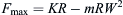 .
. -
3. The maximum power point of the load trajectory appears at the 1/4 position of the system bandwidth, the maximum load power is
 , the load speed at the maximum power point is
 and the load force is
 .
.
- 4. As long as the maximum no-load speed and maximum output moment of the rudder plane are known, the load characteristics of the steering engine system under typical load conditions have been basically determined. As shown in Fig. 5.37, the actual load characteristics of a steering engine system have the maximum output load power at point N.
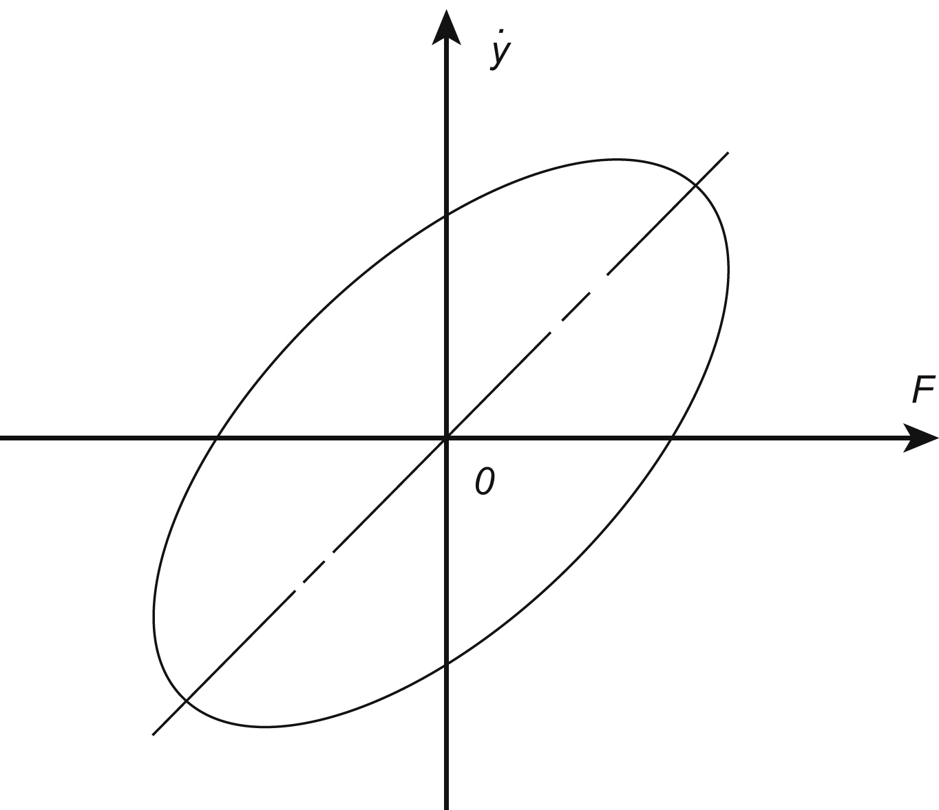

5.7.2. Optimal matching between servo mechanism output characteristics and load path
1. Energy working pressure
The installation space of hydraulic steering system is very limited, so the higher working pressure can be used as much as possible. The higher the pressure, overcoming the same load force, the smaller the piston area. At this time the servo valve needs less flow, so the size and mass of hydraulic energy and power mechanism will be greatly reduced. However, the pressure increases, so the strength requirements of hydraulic components also increase in turn, and there is a trend of increasing the volume and mass of components. In addition, the increase in pressure will increase leakage
and flow noise, oil temperature will also rise. At present, the commonly used working pressure specifications are 32 MPa, 21 MPa, 14 MPa and 7 MPa (four grades), and the working pressure of the hydraulic steering engine system can be determined according to the comprehensive factors such as volume, quality and noise.

2. Optimum power matching design
According to the load trajectory and the pressure of the hydraulic energy system, the no-load flow rate of the servo valve and the effective area of the actuator piston can be obtained under the optimum matching design condition. The output characteristic of the power control element adapts to the load track characteristic, and load matching is achieved. On the one hand, power control output characteristics fully envelope load characteristics, to meet the requirements of full load drag. On the other hand, the output characteristics of the power control element and the load characteristics match each other at the maximum power position – that is, to achieve the best power matching design, improve power utilization and reduce energy consumption, the system structure and components should reduce the volume and mass as much as possible.
The electrohydraulic servo valve is a zero-opened four-through servo valve, and the actuator is symmetrical, ignoring leakage and fluid compressibility. Fig. 5.38 shows a servo valve output characteristic curve, at the maximum power point N, there is:

where
 is the servo valve no load flow, and flow when (PL = 0), and
 is the servo valve inlet operating pressure (Pa).
When the maximum output power point N’ of servo valve is coincident with the maximum power point N of the load track, the optimum power matching is achieved, and the hydraulic energy consumption is the minimum. From Eqs (5.6)–(5.9), we have:
where:
where:
So:
Eqs (5.10) and (5.11) are the optimum design formula of actuator piston effective area A and servo valve no-load flow Q
0 under the optimum power matching condition. In engineering practice, this is often done rounding according to the above calculation results, or according to the existing product samples, selecting the appropriate specification actuators or servo valves and other components, and then checking these.
5.7.3. Energy demand status of actual rudder system
The hydraulic rudder system of ground-to-air and air-to-air missiles uses the method of four rudders that share one hydraulic energy source. On the whole trajectory of the missile, the level of energy consumption is uneven. For most of the work time, the energy consumption level is lower, only at the beginning of a certain point, and close to the target, may power demand be relatively large. In addition, the four rudders normally do not work at the same time; the probability of maximum demand for four rudder planes in the same time is minimal. Based on above two reasons, combined with model products, telemetry flight results and design experience, it is recommended that the energy power be designed to be 67–75% of the maximum power. In this way, the system not only meets the actual working conditions, but also greatly reduces the specifications and the volume and mass of rudder system and parts, so as to facilitate the miniaturization and integration of the system design.
5.7.4. Work pressure variety and systematic frequency characteristics
1. Influence factor of working pressure
The design of the steering engine system is based on constant working pressure and optimum condition. This situation is very rare in practice. Therefore, it is of great significance to analyse the working conditions of the system under varying pressure. Electrohydraulic servo valve is the core component of hydraulic steering system, and its technical performance has a great influence on the whole system. The servo valve transfer function is an approximately linear analytical expression of the dynamic characteristics of the servo valve. The time dynamic characteristic of the servo valve is related to input signal amplitude, oil supply pressure, oil temperature, environment temperature, load condition, etc. Usually, the valve coefficients are obtained under the assumption that the supply pressure is constant. The actual working process of the aircraft steering engine system is a complex process, and the inlet pressure of the servo valve is unstable, mainly because of the following aspects:
- 1. Variations of ballistic conditions and external loads.
- 2. The interplay of multiple loops in parallel or subsystems.
- 3. Primary energy work instability, including power characteristics, gas energy high temperature and low temperature performance differences, hydraulic pump variable characteristics and the volume of work process efficiency decreased.
- 4. The difference between the actual operating point of the relief valve and the adjustment operating point, i.e. the operating point deviation.
2. Simulation results of amplitude phase frequency characteristics
According to the dynamic technical indexes under different working pressure conditions, bandwidth and so on of a sample of the servo valve, according to the actual application conditions, the three system values of the electrohydraulic servo valve are fitted in the range of the change of the working pressure. As shown in Fig. 5.39, the amplitude, phase and frequency characteristics of a steering engine system under variable pressure are
simulated. When the system working pressure drops, the coefficient of servo valve changes and results in a decrease in the amplitude of the output frequency response. In the design of the hydraulic steering engine system, it should be guaranteed that the output frequency characteristics can meet the actual requirements in the minimum allowable working pressure range.
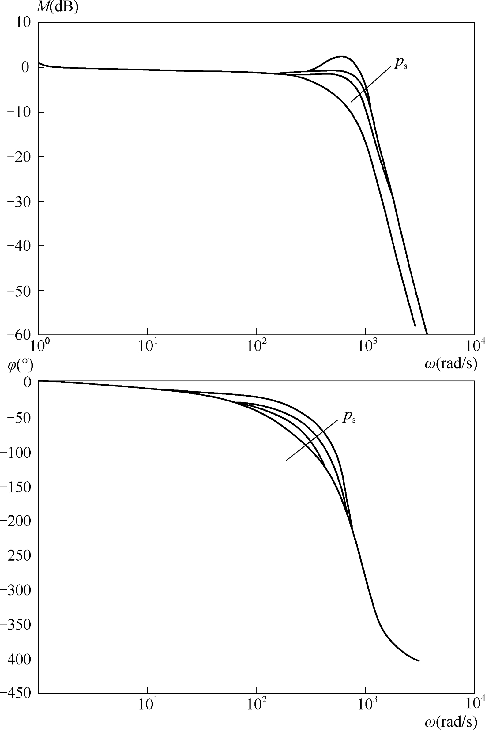
5.7.5. Conclusions
- 1. For a hydraulic steering system subjected to inertial loads, or inertial loads coupled with an elastic load, maximum load speed and maximum load do not occur at the same time. The time curve of the load force and the load speed differs by half of the movement period, and the load trajectory is a positive ellipse.
- 2. Under the optimal load power matching condition of the steering gear system, the effective area of the actuator piston and the no-load flow of the electrohydraulic servo valve can be designed according to Eqs (5.10) and (5.11). The actual power of the hydraulic energy system can be designed according to 67–75% of the maximum power when the hydraulic power is shared by multiple rudders.
- 3. The stability of system work pressure is influenced by many factors. When the pressure changes, the output frequency characteristics of the system changes, the analysis and design of steering engine system should ensure the output frequency characteristics can meet the steering engine system bandwidth requirement in a certain working pressure range.
..................Content has been hidden....................
You can't read the all page of ebook, please click here login for view all page.