
Chapter 10
Hydraulic Components in Extreme Temperature Environments
The performance of hydraulic components in extreme environments affects the service characteristics of hydraulic systems. This chapter introduces analysis methods for hydraulic components, gas bottle and gas chamber characteristics of accumulators at extremely low temperatures (-40°C) and extremely high temperatures (160°C), service performance of electrohydraulic servo valves and process technology and measures against extreme temperature environments.
10.1. Aircraft hydraulic accumulator and gas cylinder in extreme temperature environments
In the course of storage, transportation and launching of aircraft, hydraulic components are often subjected to extremely low temperature and extremely high temperature environments. Storage conditions include extreme low temperature (-40°C) and extreme high temperature (160°C) conditions. Characteristics of hydraulic accumulators and gas bottles over a large temperature difference range, especially inflation pressure characteristics and inflated mass of gas in chamber, and characteristics of working oil discharge and maximum oil filling capacity of accumulator, are of vital importance to the design of aircraft hydraulic systems.
10.1.1. Applications at extreme temperatures
Servo control originated from the attitude control systems of missiles and rockets developed before and after the Second World War. The gas servo system of gas generator, pneumatic servo valve and gas motor was adopted. Since 1950, the United States, Soviet Union/Russian Federation and other European countries have developed thrust vectoring control and rocket
attitude control systems for space rockets and space vehicles, adopting cooled air or thermal gas driving pneumatic servo actuators or hydraulic actuators to perform servo control. The Chinese Chang Zheng series launch vehicle attitude control system executing mechanism uses a cylinder gas source to drive a pneumatic vane, driving a hydraulic pump or motor pump to produce hydraulic energy. Problems with the storage and emission of gas, gas-fired driving and reliability of gas cylinder systems of aircraft have not been completely solved in extreme temperature environments. It has been listed as an important subject. In aircraft hydraulic control systems, a hydraulic accumulator and gas pressurization tank are usually adopted. The hydraulic accumulator uses the compressibility principle of sealed gas to work. Oil absorption and oil discharge are realized by compression and expansion of chamber volume and pressure changes. To ensure normal operation of the hydraulic control system and to improve high-altitude performance of the hydraulic system, aircraft use pressurized fuel tanks. Pressurized fuel tanks, used when aircraft are flying at high altitude, under the action of gas pressure, pressurizes sealed oil stored in the tank, increases the pressure on the fuel tank surface to facilitate suction of the hydraulic pump and prevents suction of the hydraulic pump from cavitation.
Air defence missile autopilot rudder control and seeker antenna servo mechanisms often use hydraulic energy. For example, the US Hawke missile uses a hydraulic steering engine to control rudder deflection; the Soviet S-300 missile initially adopted a gas steering engine, but later changed to a hydraulic steering engine; the US Patriot air defence missile uses an electric variable pump hydraulic steering engine; the US Sea Sparrow series missile uses solid gas generator driving gas and liquid accumulator type seeker hydraulic energy and nitrogen gas driving gas and liquid accumulator type pilot hydraulic energy source; the British Sea Dart ship-to-air missile uses a gas motor driven hydraulic steering engine; the Italian Aspide armed forces general air defense missile uses gas turbine pump electrohydraulic power driven pilot hydraulic steering engine and antenna hydraulic servo mechanism. Aircraft storage temperature range is generally -40°C ∼ 60°C. Missile or rocket hydraulic steering engines or servo mechanisms mostly use a small capacity, high pressure, closed hydraulic system, the hydraulic oil extreme working temperature of which can reach 160°C or even higher. Hydraulic components of aircraft must be able to operate normally in a wide range of temperatures, but working performance problems under extreme low temperatures and extreme high temperatures will become more complex.
On the ground, the accumulator gas chamber and pressurization tank gas cylinder are inflated and filled with a certain amount of pressure. In the period of aircraft storage, transportation and launching, the range of temperature can vary greatly. How to ensure the normal operation of the gas chamber and its hydraulic accumulator across the whole temperature range is of great importance. At present, there is much researches and discussion on performance of hydraulic accumulators under conventional environmental conditions. However, research on performance of accumulators under extreme temperatures is still rare. This section studies air performance of hydraulic accumulators and cylinders at extremely low and extremely high temperatures in the storage state of aircraft and inflation pressure characteristics and inflated mass of gas over a large temperature range. Characteristics of oil discharge and the maximum oil filling capacity of accumulator are analysed and charging pressure characteristic curves of different gases are obtained.
10.1.2. Van der Waals equation of actual gas
Aircraft often use hydraulic accumulators to absorb pressure shocks or supply hydraulic energy, or to charge the oil tank of a closed hydraulic system through gas stored in a gas cylinder. The pressure of gas in a hydraulic accumulator or gas cylinder varies with the temperature of the storage environment, and the range of environmental temperature changes is usually relatively large. For example, if the environmental temperature is -40°C in winter and the air chamber is inflated, when it is used in summer, air temperature is 60°C – an increase of 100°C – and the pressure of gas in the hydraulic accumulator or gas cylinder increases greatly, perhaps exceeding the specified scope of use. Therefore, when aircraft air chamber is inflated, often according to actual working conditions, according to autumn winter and spring summer two groups using states, charging management is carried out respectively, in order to ensure aircraft hydraulic system air chamber pressure in normal range. In different conditions, real gas and ideal gas are very different. Real gas is governed by the state equation of ideal gas when its density is not too large, temperature is not too low (compared with room temperature) and pressure is not too high (compared with atmospheric pressure). At high or low temperatures, the state of real gas varies greatly from the state equation of ideal gas. In engineering analysis and application research, it is often necessary to make corrections on the basis of ideal gas when dealing with extremely high
pressure or extremely low temperature gas characteristics. Real gas takes into account the microscopic theory of material structure, such as volume of gas molecules and interaction forces between gas molecules, which can better reflect objective reality.
The state equation of the ideal gas is,
where:
The Van der Waals equation of the real gas is,
where:
a and b are determined by the pressure, volume and temperature at critical inflection point of gas, liquid and solid three-phase of measured gas, and,
In which,
For dry air, there is T
k = -140.7°C, p
k = 37.2 MPa. Van der Waals constants of several kinds of gas are shown in Table 10.1.
10.1.3. Charging mass of high pressure gas cylinder
For chambers of a certain volume, such as the gas chamber of a hydraulic accumulator or the gas cylinder of a gas pressurization tank, normally pre aeration is performed at a certain temperature at ground level, and the
charging mass when a specified pressure is reached can be determined by Eq. (10.2). Eq. (10.2) is deformed, and the follow is obtained,
Table 10.1
| Gas | Molecular formula | M (g/mol) | a (10 −1·m6·Pa/mol2) | b (10 −6·m3/mol) |
|---|---|---|---|---|
| Atmosphere | 28.97 | 1.36 | 36.51 | |
| Nitrogen | N2 | 28 | 1.41 | 39 |
| Helium | He | 4 | 0.034 | 24 |
| Argon | Ar | 40 | 1.357 | 32 |

The minimum inflation pressure p
min and the maximum inflation pressure p
max of the hydraulic accumulator are usually determined according to the amount of oil required by the hydraulic system. By specifiying low temperature and minimum inflation pressure, charging masses of a group of gasses in a certain volume can be obtained by Eq. (10.5), namely, mass of inflation in autumn and winter. From specifying high temperature and maximum inflation pressure, charging masses of another group of gases can be obtained through Eq. (10.5), that is, mass of inflation in spring and summer. The charging masses of these two sets of gases are determined by two charging curves. For example, the normal operating pressure of an aircraft hydraulic system is 21 MPa, and within the temperature range of -40–60 °C, the allowable charging pressure range of the accumulator and small gas cylinder is 12.5–18.0 MPa. By two sets of conditions of autumn and winter -40 °C, 12.5 MPa, and spring and summer 60 °C, 18.0 MPa, through Eq. (10.5), the charging mass of two charging curves of autumn and winter, and spring and summer can be solved, respectively. Through two sets of charging pressure curves, the storage pressure of the hydraulic accumulator or gas cylinder is guaranteed within the specified scope of use.
10.1.4. Gas pressure characteristics of high pressure gas cylinder and chamber
For a certain volume of accumulator chamber or gas booster tank cylinders, at completion of ground state after inflation, the pressure of a certain mass of gas in the chamber varies with aircraft storage, transport and launching temperature. From Eq. (10.2), the state equation of real gas satisfies,
Eq. (10.6) reflects the change law of pressure of a certain mass of gas with temperature. Gas pressure is linearly related to thermodynamic temperature of the gas and is related to a number of moles m/M of gas and constant of gas a, b. The smaller the molar number of gas m/M, the greater the gas constant b, and the smaller the slope of the pressure-temperature curve, shown by Eq. (10.6), the more stable the pressure variation with temperature.
The charging air pressure characteristics of air or nitrogen gas are shown in Fig. 10.1. The air chamber volume of an aircraft is 490 cm3, and its hydraulic system operating pressure is 21 MPa. In the -40–60°C temperature range, in order to ensure normal operation of the hydraulic accumulator, the gas charging pressure is below 21 MPa, that is 12.5–18.0 MPa. In two sets of temperature fields of -40–23°C (autumn and winter) and -13–60°C (spring and summer), the gas chamber of the hydraulic accumulator is inflated by the corresponding inflation curve respectively.
Fig. 10.2 shows theoretical calculation results using the state equation of ideal gas and real gas Van der Waals equation. The theoretical calculation results show that in high pressure, extreme low temperature conditions, gas pressure characteristics calculated by the state equation of ideal gas and that
by the real gas state equation (i.e. the Van der Waals equation) have great difference, and the state equation of ideal gas cannot accurately describe gas pressure characteristics. At this point, the state equation of real gas must be used.
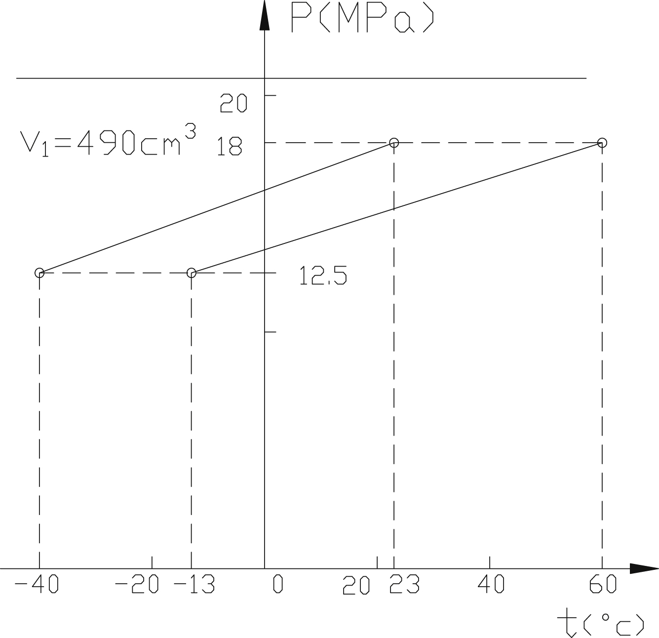
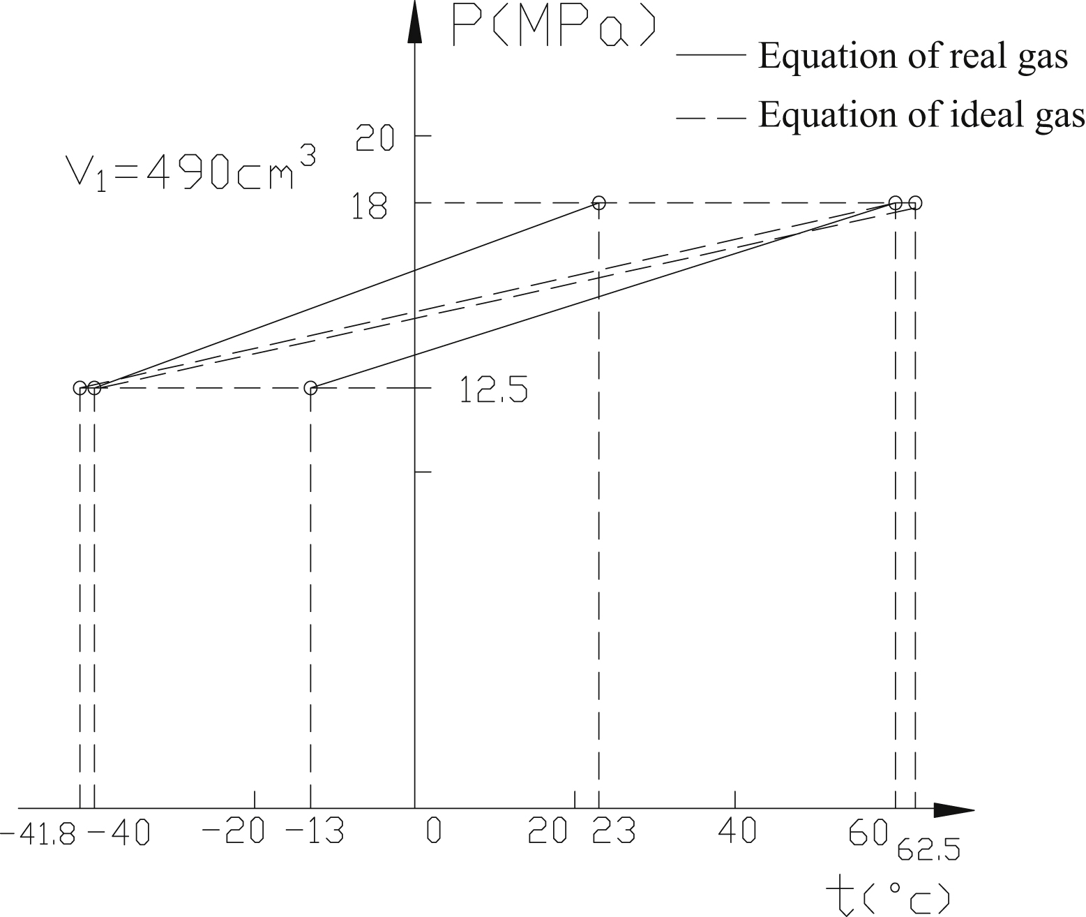
Fig. 10.3 shows a set of pressure variation characteristic curves for several different gases; state equation of real gas, i.e. van der Waals equation calculation results, are used. As can be seen from the diagram, using helium as a working medium, a charging curve of 12.5–18.0 MPa at a temperature range of -40–60 °C can be achieved. However, the cost of helium is relatively high.
10.1.5. Accumulator characteristics
Fig. 10.4 shows the three main stages of the use of a hydraulic accumulator. Fig. 10.4A is the state of the hydraulic accumulator when it is just beginning to work; Fig. 10.4B is the state of maximum operating pressure of the hydraulic accumulator; Fig. 10.4C is the state of minimum working pressure of the hydraulic accumulator.
The hydraulic accumulator working process is a short period of oil filling and oil discharging; gas volume changes fast, no heat is exchanged with the outside world, the state change process of gas in the accumulator
can be considered as an adiabatic process. For gas in the accumulator chamber, there is,


where:
n is the adiabatic index of gas compression and expansion in the process of charging and discharging of accumulator, 1.0≤n≤1.4;
 (10.9)
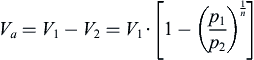
The working oil supply capacity of the hydraulic accumulator is,
 (10.10)
In order to reduce mass and volume, the volume of the tank in a hydraulic system can be designed to be as small as possible to meet the change of volume of liquid during the flight. In the course of an aircraft's operation, the maximum volume of oil from the system into the hydraulic accumulator (that is, the maximum charge capacity of the accumulator), is an important index for the design of the hydraulic accumulator, pressurized fuel tank and closed hydraulic system of the aircraft, which must be taken into full consideration. Eqs. (10.9) and (10.10) reflect the maximum oil filling capacity and the volume of oil supply when the accumulator works. Theoretical calculation results are shown in Fig. 10.5. When the accumulator is used to store energy, the charging pressure has a great influence on the maximum oil filling capacity and the volume of oil supply. During analysis and design of the closed hydraulic system of an aircraft, thermal expansion or shrinkage of hydraulic oil at extreme temperature should be considered. According to the actual working conditions it will be necessary to adjust the capacity of the hydraulic accumulator and pressure tank to absorb or compensate for the volume change caused by thermal expansion of hydraulic oil.
10.2. Electrohydraulic servo valve in extreme temperature environments
As the core component of a hydraulic servo system, the performance of electrohydraulic servo valves (such as zero position, gain, hysteresis width) determines the characteristics of electrohydraulic servo systems directly. When the ambient temperature changes, the sliding pair clearance between
the hydraulic slide valve spool and valve sleeve changes, which can cause phenomena such as wear, sticking, clamping stagnation, increased pressure loss or increased leakage between spool and valve sleeve. Oil viscosity changes with oil temperature and the throttling action at the valve opening produces temperature rise, resulting in uneven temperature distribution in the valve: the valve is locally heated, causing spool and valve sleeve thermal expansion to occur. The properties of magnetic materials are also affected by temperature, including the effect of ambient temperature on dimension of slide valve parts of electrohydraulic servo valves and fit clearance, flow field distribution and temperature distribution in the valve at different initial temperatures, as well as high and low temperature characteristics of hydraulic oil, and the influence of temperature on the permanent magnet and guide magnet.

10.2.1. Influence of temperature on fit clearance of electrohydraulic servo valves
Temperature changes cause electrohydraulic servo valve components and their matching dimensions to change, which can affect the performance of the valve. The most direct influence on hydraulic components is expansion and contraction caused by the change of ambient temperature. Deformation of parts and clearance between them are changed: excessive clearance
increases valve internal leakage; too little clearance and the spool and valve sleeve can easily become stuck. Electrohydraulic servo valves are of small size, and components of servo valve are smaller in size, and many of them have special shapes. For example, the feedback bar is a thin and long elastic rod with a maximum diameter of only 1.5 mm and a length greater than 30 mm; one end of the feedback rod is a cylinder, the other end is a sphere with a millimetre scale, and the middle part is a cone; the central wall of the spring tube is 0.05–0.07 mm thick and needs to bear the pressure of 30 MPa; the baffle is also a slender component, the large end diameter is only 3 mm, and there is a 1.5 mm precision hole, the small end has two symmetrical small planes. Other parts, such as nozzles and throttle holes, are also small and special parts.
Each part of the electrohydraulic servo valve is provided with various axial sizes and radial size matching conditions, for example:
- • clearance fit between valve core and valve sleeve is 2–4 μm;
- • interference fit between valve sleeve and valve body is 2 μm (or clearance fit 2 μm);
- • interference fit between armature centre bore and small end diameter of spring tube is 8–12 μm;
- • interference fit between spring tube middle hole and large end of baffle is 4–6 μm;
- • interference fit between baffle inner diameter and feedback rod is 3–5 μm;
- • the ball under the feedback bar and the middle groove of the valve core are meshed without gaps; and
- • nozzle and valve body are in interference fit, and the press-in amount of the front end of nozzle is 4–7 μm.
When the temperature decreases, the closeness of fit decreases and clearance increases, causing too much leakage, large electrohydraulic servo valve null shift, the servo valve orifice assembly of some structures will move inside valve body, and other phenomena. When the temperature increases, interference fit size can increase, causing fit stress and deformation. In addition, when the temperature increases, taking the small ball as the centre, the valve core thermally expands at both ends, the valve sleeve is axially symmetrically expanded within the valve body, and asymmetry of axial fit may cause zero drift phenomenon.
The thermal expansion coefficient of a material is expressed in terms of coefficient of linear expansion. It means that if the temperature increases by 1°C, the elongation per unit length is (1/°C). According to the mechanics
of materials, when the temperature of the object rises by Δ, the elongation of the material is,
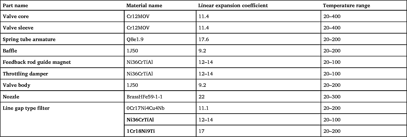
The average coefficient of linear expansion of several kinds of materials used in electrohydraulic servo valves in an aircraft is shown in Table 10.2.
Some precision matching pairs using these engineering materials have a small gap between them; this is necessary to ensure that contained parts can move back and forth in the container, but also to ensure tightness and minimize leakage. This requires the design of precision matching parts as far as possible to consider the use of thermal expansion coefficient of smaller or similar materials for matching parts, in order to ensure their temperature adaptability and reliability. As temperature changes, the size of electrohydraulic servo valve parts changes, which affects output performance of the valve. When the closeness of fit is reduced, large zero drift of the electrohydraulic servo valve will be caused, and the orifice assembly will move within the valve body. When temperature increases and interference fit size increases, stress at joints will increase, and deformation will increase in severe cases.
The standard sealing material for electrohydraulic servo valves is nitrile rubber (NBR). The sealing material must be suitable for the hydraulic fluid. For petroleum based hydraulic oil, sealing materials such as NBR, fluorosilicone rubber, etc. can be used; when the hydraulic fluid is anti-fuel
oil, such as phosphate hydraulic oil, butyl rubber should be used. When choosing a sealing material, the working environment of the valve and the temperature of the hydraulic fluid should also be considered. The material grade of NBR is 5080. Its environment and hydraulic fluid environment temperature range is -40–150°C. Fluorosilicone rubber is softer and its strength is less than 5080. At low temperatures, NBR seals will incur a hardening, cold brittle phenomenon and material elasticity decreases; low temperatures lead to interference magnitude reduction, causing the valve sleeve and valve body sealing surface contact pressure to drop and leakage increases. At the same time, because of the low elastic deformation and restoring ability of the material at low temperature, the seal's ability to follow the eccentricity decreases. At high temperature, rubber seals, hoses and other devices are prone to premature ageing; the material loses elasticity, strength decreases, pressure resistance decreases and permanent deformation increases and leads to failure. The higher the operating temperature, the greater the permanent seal deformation of O-type rings. When permanent deformation is greater than 40%, an O-type ring will lose its sealing capacity and leak. When working at low temperatures, the initial stress of rubber material O-type ring compression deformation will gradually decrease, or even disappear, with the relaxation process of the O-type ring and decrease in temperature.
Table 10.2
When the temperature changes, the variation of radial fit clearance between valve sleeve and valve core is composed of two parts: one part is variation of the inner radius of the valve sleeve; the other part is variation of the spool radius. The variation of radial clearance between the valve core and valve sleeve can be approximately expressed as:
where:
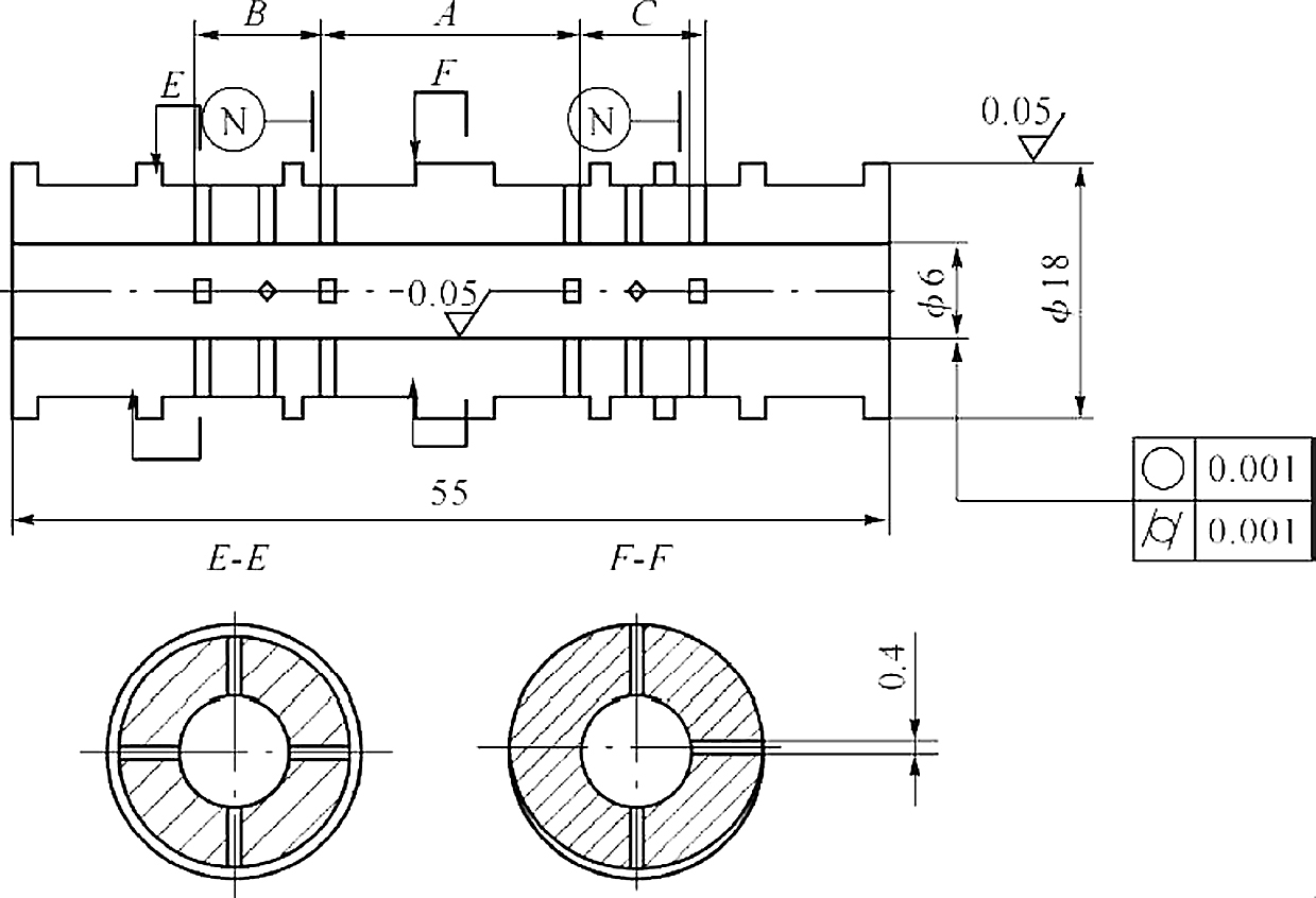
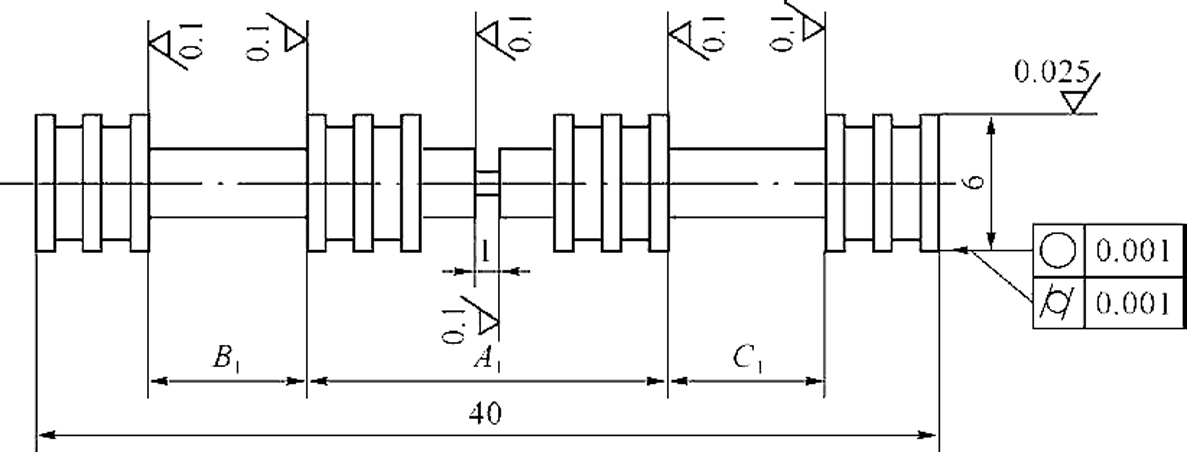
Figs. 10.6 and 10.7 are structure sketch maps of the valve sleeve and the spool of an electrohydraulic servo valve of an aircraft, respectively. Among them, A, B and C are axial fit distances between throttle windows of the valve sleeve. The inner diameter of the valve sleeve is 6 mm, the outer diameter is 16 mm, and the clearance between the valve core and valve sleeve
is 4 μm at normal temperature; when the temperature increases, the clearance between them decreases. When the temperature is too high, the relative movement between valve core and valve sleeve is affected, which may lead to sticking. At an environmental temperature of 25°C, when the hydraulic oil temperature has increased to 120 °C, the coefficient of linear expansion of materials of the valve core and valve sleeve is α1=11.4×10
−6/°C, according to Eq. (10.12) and valve sleeve clearance variation can be calculated to be 3.8 μm. At this point, it is theoretically known that the matching state between valve core and valve sleeve changes from clearance fit into the critical
condition of interference fit. When temperature is higher than 120°C, it often leads to the phenomenon of sticking.
Armature and upper and lower guide magnets are subject to thermal expansion and contraction, and the air gap is changed. Under normal temperature, the initial air gap length is 0.25 mm; when temperature is 150 °C, air gap length is 0.244 mm; when temperature is -40°C, the length is 0.253 mm. The air gap change indirectly affects the flux of the control coil. When the material is heated and expanded, the gap between nozzle and baffle will easily become smaller as temperature increases, thus affecting flow rate and pressure gain.
10.2.2. Influence of temperature on viscosity of hydraulic oil
The viscosity of hydraulic oil decreases with increase of temperature, and increases with increase of pressure. Under -20–80°C viscosity of hydraulic oil varies with temperature as follows:
where:
- γ pt is the kinematic viscosity of hydraulic oil at temperature t °C and pressure p;
- γ0 is the kinematic viscosity of hydraulic oil at temperature t 0 °C and pressure 0.1 MPa;
- λ is the hydraulic oil viscosity temperature coefficient, which can be (1.8–3.6)×10-2/°C; and
- α is the viscosity-pressure coefficient, which depends on the fluid properties of liquid and can be approximated as (2–3)×10-8/Pa.
Usually, thermal expansion performance of hydraulic oil is expressed by volumetric thermal expansion coefficient. Table 10.3 shows the volumetric thermal expansion coefficient of YH-12 aviation hydraulic oil.

10.2.3. Influence of temperature on flow field of valve chamber
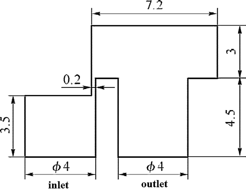
Hydraulic oil flows through the inlet of the electrohydraulic servo valve and flows out through the throttle orifice into the valve chamber. The spool valve usually has several valve chambers; one of these valve chambers is used to study the flow of fluid in the valve. As shown in Fig. 10.8, for convenience, the model is simplified to a two-dimensional model of inlet pressure 10 MPa, orifice opening 0.2 mm and outlet pressure 0.1 MPa. In order to analyse the flow field under different initial temperatures, the following assumptions are made:
- 1. The hydraulic fluid is YH-12 aviation hydraulic oil, and characteristic parameters at 50°C are shown in Table 10.4.
- 2. The fluid is incompressible and a constant Newton fluid; when flow velocity changes, its viscosity does not change.
- 3. The finite volume numerical method SIMPLE (semi-implicit method for pressure linked equations) is used to solve the discrete equations.
-
Table 10.4
Characteristic parameters at 50°C of YH-12 aviation hydraulic oil Parameters of YH-12 aviation hydraulic oil Value Parameters of YH-12 aviation hydraulic oil Value Dynamic viscosity 0.01021 Specific heat capacity 2040 Thermal conductivity 0.122 Density 847 
- 4. The wall boundary is solved by the method of no slip boundary and wall function conditions. It is assumed that wall temperature is consistent with ambient temperature.
- 5. At different temperatures, according to Reynolds number calculation results of flow and model, at low temperature -40°C is laminar, and is turbulence at 50°C and 150°C. Laminar flow is simulated by Laminar model, and energy conversion and loss in flow process are taken into account, fluid flow mass conservation equation, momentum conservation N-S equation and energy conservation equation are used to solve the fluid problems.
k-εturbulence model is adopted for turbulent flow, and turbulent kinetic energy is:
Turbulent energy dissipation is:
where:
The field is first meshed into 21520 tetrahedral meshes on Gambit, and the initial temperature is calculated by Fluent. The temperature gradient is used as the basic point, and an adaptive mesh modification function is adopted to improve the mesh and continue the operation. Calculation results are shown in Figs. 10.9–10.11.
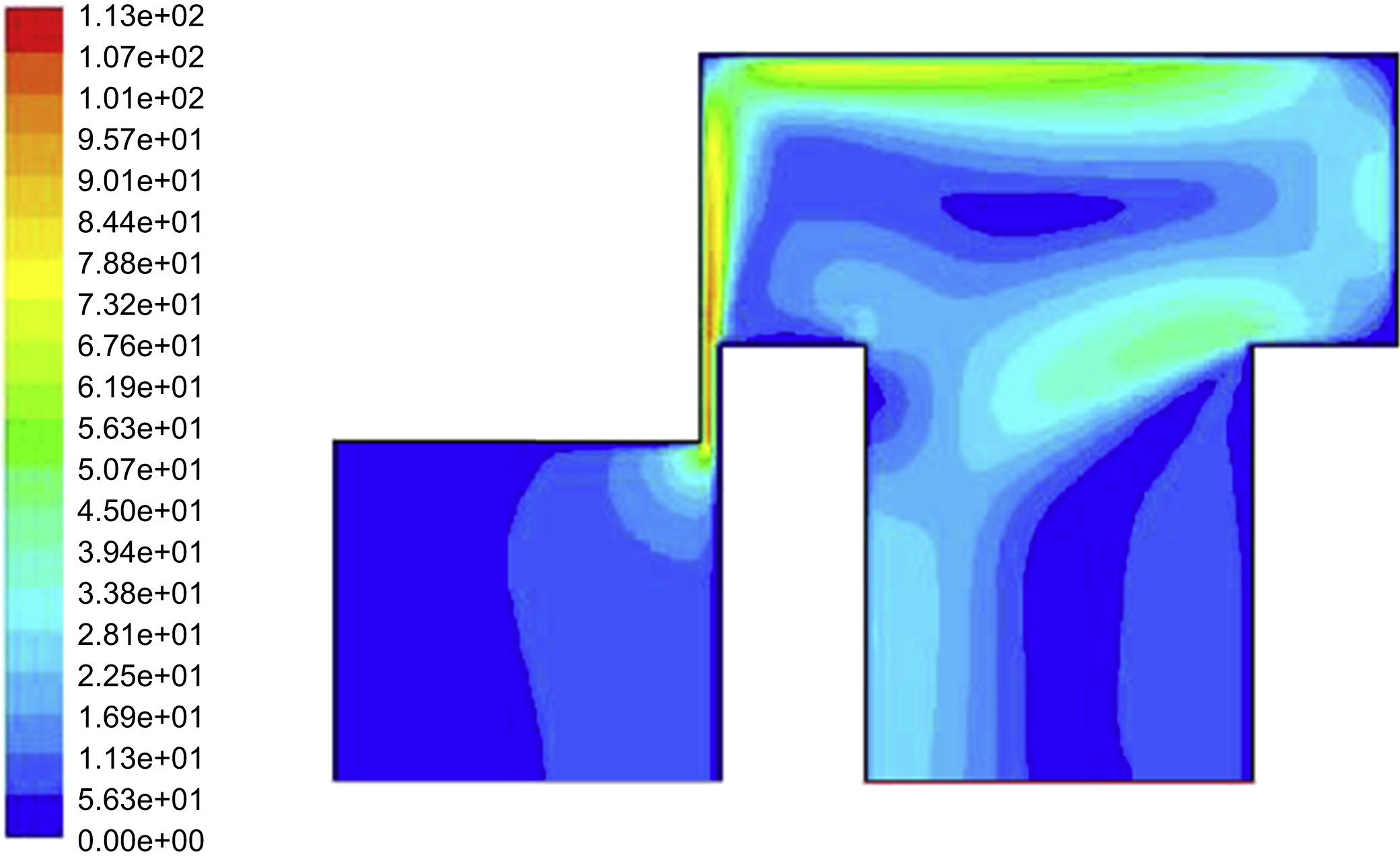
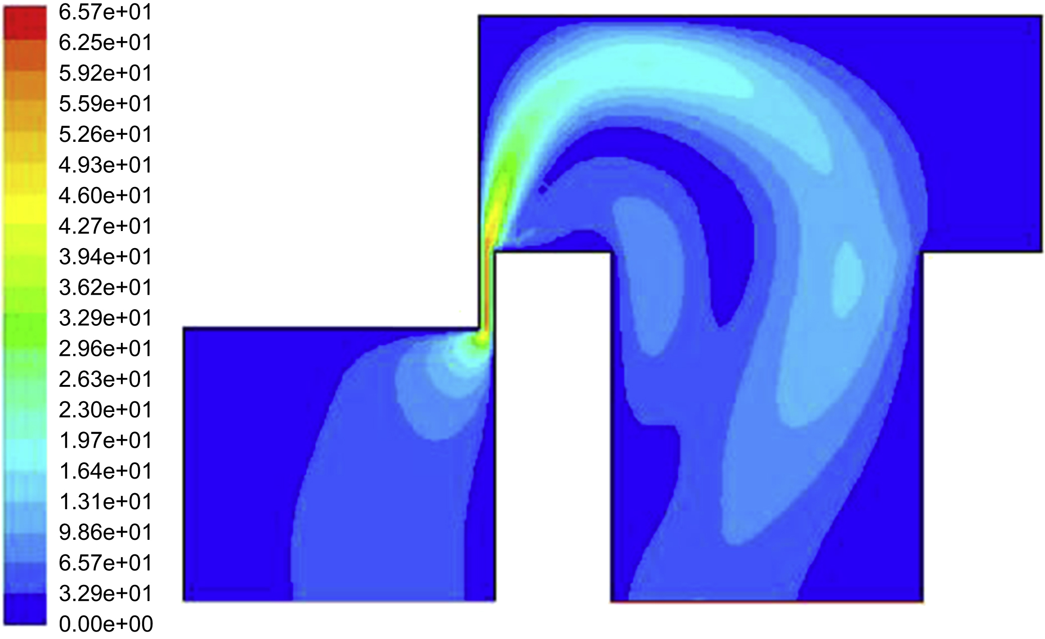
Comparison can be obtained from Figs. 10.9–10.11: the velocity in valve path appears high speed jet at throttle orifice. A vortex phenomenon appears in the valve chamber. The vortex absorbs large amounts of energy from the mainstream, increasing energy loss in the flow path and causing a temperature rise in the valve chamber. As shown in Figs. 10.9 and 10.10, the velocity distribution varies little in turbulent flow; when it is laminar flow, as shown in Fig. 10.11, exit velocity is lower than that of turbulence.
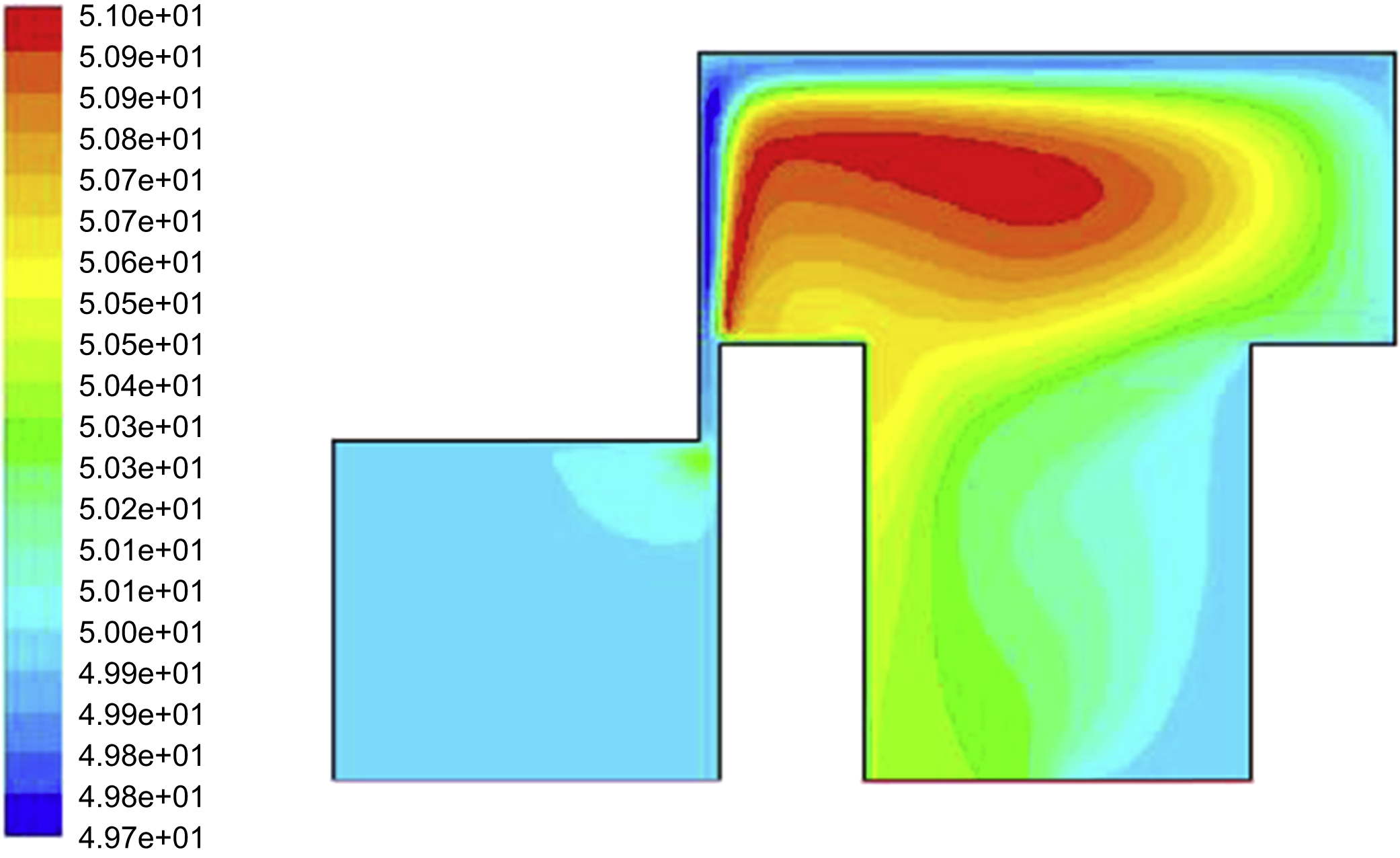
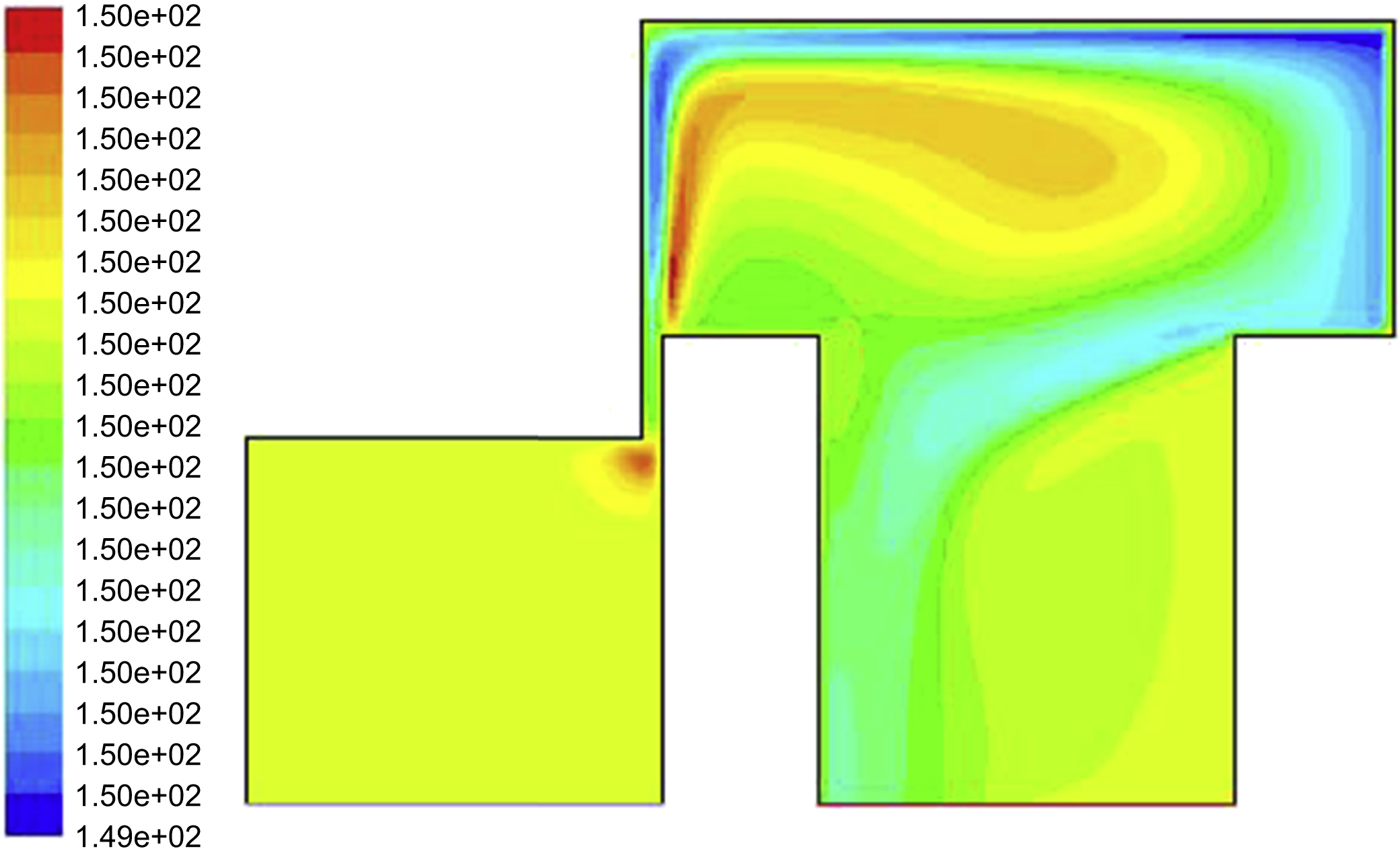
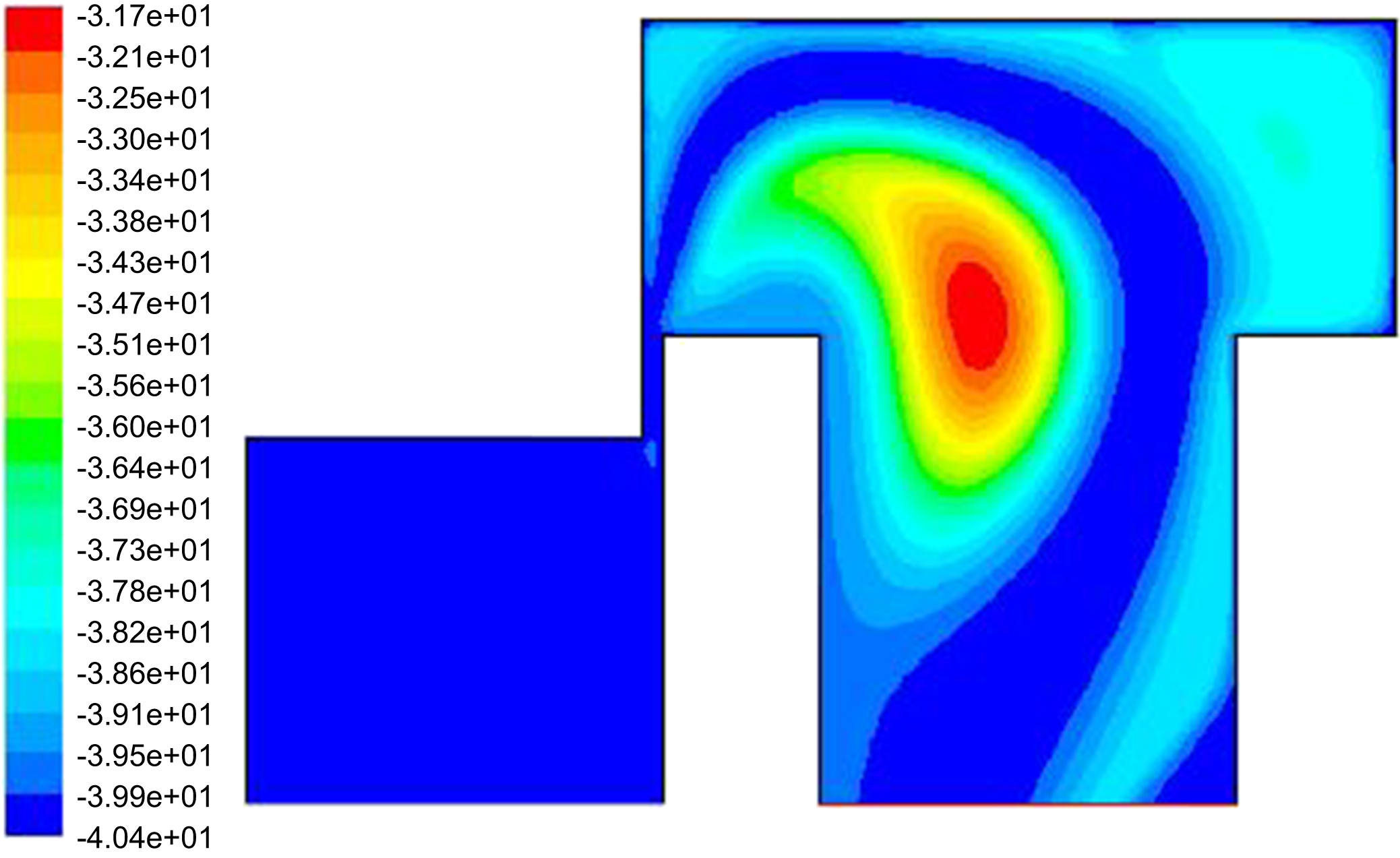
Figs. 10.12–10.14 show flow temperature distribution in the valve chamber at initial temperatures of 50°C, 150°C and -40°C, respectively. From Figs. 10.12 and 10.13 it can be obtained that, due to high liquid velocity of turbulent flow, temperature rise is concentrated at the throttle
orifice, viscous control force decreases and inertia force plays a leading role. Liquid energy is mainly consumed in the loss of kinetic energy, and has little influence on temperature rise of fluid in the valve. When it is laminar flow, as shown Fig. 10.14, viscous force plays a leading role, liquid energy is mostly consumed in friction loss between fluids, and the highest temperature at the outlet of the valve chamber reaches -31.7. For example, when
inlet pressure is 10.5 MPa, outlet pressure is 2.3 MPa, the servo valve is in the middle and temperature is high, when heat generated by throttling is transferred to the valve core, when heat balance is reached, the temperature increase of the valve core is 5–6°C; for low temperature, it is about 8°C.

10.2.4. Influence of temperature on magnetic material
Ambient temperature also affects properties of magnetic materials, which affects performance of servo valve flow and gain. The torque motor permanent magnet of an electrohydraulic servo valve is usually made of magnetic steel or Fe-Cr-Co series permanent magnetic alloy, which are
suitable for machining, or Al-Ni-Co series permanent magnet alloy, which is unsuitable for machining. At present, permanent magnet material NDFeB, which has large remanence, coercivity and magnetic energy product and high mechanical strength, is used in some electro-hydraulic servo valves. When a magnetic material is selected, the influence of coil heating caused by eddy currents, hysteresis, and coil resistance thermal power dissipation and environmental temperature should be considered. The maximum working temperature of a permanent magnet must be lower than the Curie temperature point of the material (usually at 310–400°C).
A common material used for guided magnets is Fe Ni soft magnetic alloy 1J50. When temperature rises, remanence and coercivity of hard magnetic materials decline. When temperature is in the range of -60–100°C, initial permeability of soft magnetic material 1J50 varies within the range of 4000–7000 H/m, and the maximum permeability varies within the range of 38000–50000 H/m. Permeability of soft magnetic material decreasing, and increasing of magnetic resistance will change working point.
10.2.5. Test and results analysis
I. Problems found in high temperature and low temperature performance tests of electrohydraulic servo valve
After production, manufacture and debugging of an electrohydraulic servo valve of an aircraft, tests were carried out before leaving the factory in low and high temperature (-40°C, 120°C) environments. In the environmental test process, the electrohydraulic servo valve is installed on the high and low temperature experimental equipment. The environment and oil temperature are adjusted to the temperature prescribed by technical conditions, and the oil pump is usually started after heat preservation for 24 h. A rated current sine wave signal is entered to do the flow cycle test, verifying basic functions. Then, oil circulation naturally heats up and stops after the temperature rises to the highest temperature. The temperature drift range and amplitude are recorded.
During some tests, it was found that some electrohydraulic servo valves were tested at high and low temperatures (-40°C, 120°C) without any problems. After normal temperature is restored, the performance is tested at temperatures of 0°C, 40°C, 70°C, and a sawtooth wave curve appears in the flow. In addition, it is often found in the experiment that if an electrohydraulic servo valve shows a large temperature zero drift, its nozzle end will have a larger burr; if this is replaced with a nozzle without a burr or a small burr, temperature drift can be reduced significantly; when the throttle
hole shape is poor or has a large burr, temperature drift of the servo valve is large; If the position of the left and right nozzles or throttling holes is swapped, temperature drift can be reversed.
II. Reason analysis
- 1. Combined with the structure of the electrohydraulic servo valve, considering the change of hydraulic oil temperature from low temperature to high temperature, increasing of oil temperature may cause changes in fluid flow between the throttle orifice and nozzle baffle. Through heat transfer between oil and valve elements, thermal expansion and cold contraction of internal parts caused changes in nozzle valve characteristics and nozzle baffle spacing changes, especially asymmetry of flow coefficient of nozzle and flapper increases. Thus, fluctuation of oil pressure, which leads to increased transient asymmetry of oil pressure in nozzle chamber, causes fluctuation between pressure and flow.
- 2. When the hydraulic system is at low temperature, the flow state of liquid is changed due to temperature rise, when wall flow at low temperature turns into free flow, the flow presents an unstable state. When the flow regime changes, the flow coefficient changes suddenly; this may lead to sudden changes in valve output and flow jump phenomenon.
- 3. When the nozzle is affected by oil contaminants, such as burrs, metal particles, and particles produced during operation, the nozzle outlet may be blocked or partly blocked. When the nozzle is partly blocked, output flow will drift.
- 4. In one test, there is less oil in the oil tank, causing temperature to rise quickly to 5–10°C/min, reaching 100°C in a very short time.
III. Process measures adopted to solve the above problems
- 1. During production and manufacturing of the electrohydraulic servo valve, the nozzle should be screened – that is, flow matching and pressure matching screening.
- 2. Hydraulic temperature matching tests should be added – three groups of temperature matching screening, such as 0°C, 40°C, 70°C.
- 3. In production and processing, the influence of nozzle ring width and coaxiality on nozzle output should be considered: special cutting tools and tools used to machine fixed orifice and nozzle hole; steps taken to screen out qualified matching products by changing tolerances and increasing testing, ensuring that nozzles of the same servo valve have the same nozzle inner diameter, thus reducing faults caused by asymmetry of nozzles.
- 4. In order to reduce zero drift of viscosity with temperature, the symmetry of hydraulic amplifier should be guaranteed, and influence of viscosity on flow performance should be reduced, required good orifice pass, no burr, throttling length as small as possible, nozzle pass well, the end ring as narrow as possible, no burr. To do this, it should make orifice and nozzle matrix have higher hardness, pass and ring should have grinding process.
..................Content has been hidden....................
You can't read the all page of ebook, please click here login for view all page.