Chapter 11
Electrohydraulic Servo Valve in Vibration and Impact Environment
With use of the whole machine, an electrohydraulic servo mechanism often needs to withstand various vibration and environmental impacts. During flight, an aircraft is affected by various environmental factors, especially the complex impact and vibration. Ideally for laboratories on the ground, an electrohydraulic servo valve body is stationary, the displacement, speed and acceleration of valve body are zero, and the motion state of each part of the electrohydraulic servo valve is not affected by implicated motion. When the whole machine which electrohydraulic servo valve located, such as servomechanism components, subject to vibration and impact, the valve body of the electrohydraulic servo valve is no longer static. All parts of the valve body are affected by implicated motion and change into resultant motion – that is, each component within the valve has relative motion to the valve body, while the valve body is in motion relative to the absolute coordinate system.
The vibration impact signals studied here fall into three categories: unit step acceleration signal, unit pulse acceleration signal and vibration signal. The force feedback type two-stage electrohydraulic servo valve, such as the electrohydraulic servo valve of an aircraft and the Moog31 electrohydraulic servo valve, is taken as the object of analysis. The characteristics of electrohydraulic servo valve under unit step acceleration and unit pulse acceleration are analysed, and the frequency response characteristics of the electrohydraulic servo valve in a vibration environment, impact resistant measures and vibration control measures are also investigated.
11.1. Mathematical model of electrohydraulic servo valve in vibration and impact
Vibration signals studied have the same direction as that of the main slide valve spool movement, both of which are in the direction of x. The
electrohydraulic servo valve body is translational in x direction. The resultant motion law of translational transport motion is as follows:
where:
-
 ,
,
 and
and
 are the absolute displacement, absolute speed and absolute acceleration of the main slide valve spool, respectively;
 -
 ,
,
 and
and
 are the displacement, velocity and acceleration of the main valve core relative to the valve body, respectively; and
 -
 ,
,
 and
and
 are the displacement, velocity and acceleration of valve body relative to absolute coordinate system, respectively.
After being transformed, there are:
In order to obtain a mathematical model of the electrohydraulic servo valve in a vibration and impact environment, some mathematical expressions involved in ideal condition should be adjusted accordingly. When the baffle of the double nozzle flapper valve has displacement x
f, two load ports of the double nozzle flapper valve have flow Q
1, Q
2, and the pressures of the two control chambers are p
1p, p
2p, respectively. The pressure of the return oil overflow chamber between the two nozzles and return orifice is p
r, and the volume is V
r. The volume of the oil will be compressed after it is compressed, considering the compressibility of the hydraulic oil of the double nozzle flapper valve and the main valve’s two chambers. THe control pressure equation of main valve core can be obtained as follows:
Through analysis of the force of the slide valve, the equation of motion of the slide valve can be obtained as follows:
As the slide valve core moves, the ball head of the feedback rod is pulled, and the feedback rod has flexible deformation. The force equilibrium equation of the feedback bar is:
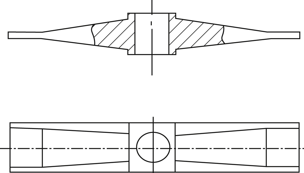
In addition, the armature baffle assembly is rigidly connected with the top end of spring pipe, and the spring tube is an elastic element. When the servo valve body vibrates, the armature baffle assembly is also affected by the influence of transport motion, as shown in Fig. 11.1.

The centre of mass of the armature baffle does not coincide with the rotating centre of spring tube, and is separated by d
e. Tangential acceleration and normal acceleration are obtained by decomposition of convected acceleration. Force produced by normal acceleration and mass of the armature baffle assembly can be balanced by the spring tube. Force produced by tangential acceleration and mass of the armature baffle assembly are perpendicular to the centre line of the armature baffle. This force will produce additional torque to the spring tube. Since
 is quite small, there is:
The armature is supported by a spring tube and is suspended between air gaps of upper and lower guide magnets. It is deflected by an electromagnetic moment, because it is rigidly connected with the baffle feedback rod assembly, so it is also affected by the baffle’s hydraulic dynamic moment and aligning torque of the feedback rod. The moment equilibrium equation of the armature is:
The equations above form the mathematical model of an electrohydraulic servo valve in a vibration and impact environment. According to this mathematical model, the characteristics of electrohydraulic servo valve in a vibration and impact environment can be analysed by mathematical calculation and simulation. It can be seen from Eqs. (11.2) and (11.4) that vibration signals in acceleration form are the most convenient to study. The following vibration and impact signals are in the form of acceleration.
11.2. Electrohydraulic servo valve in unit step acceleration environment
The force feedback type electrohydraulic servo valve, such as the electrohydraulic servo valve of an aircraft and the Moog31 electrohydraulic servo valve, is taken as the example. According to the mathematical model mentioned above, in a unit step acceleration environment and at different structural parameters, that is when load pressure of electrohydraulic servo valve, mass of armature baffle assembly, mass of main valve core, stiffness of spring tube, distance between centre of mass of armature baffle assembly and centre of rotation of spring tube, volume of a single control chamber of nozzle flapper amplifier changes, response characteristic of main valve displacement, baffle displacement and armature displacement can be obtained by mathematical simulation of the above equations.
11.2.1. Influence of load pressure
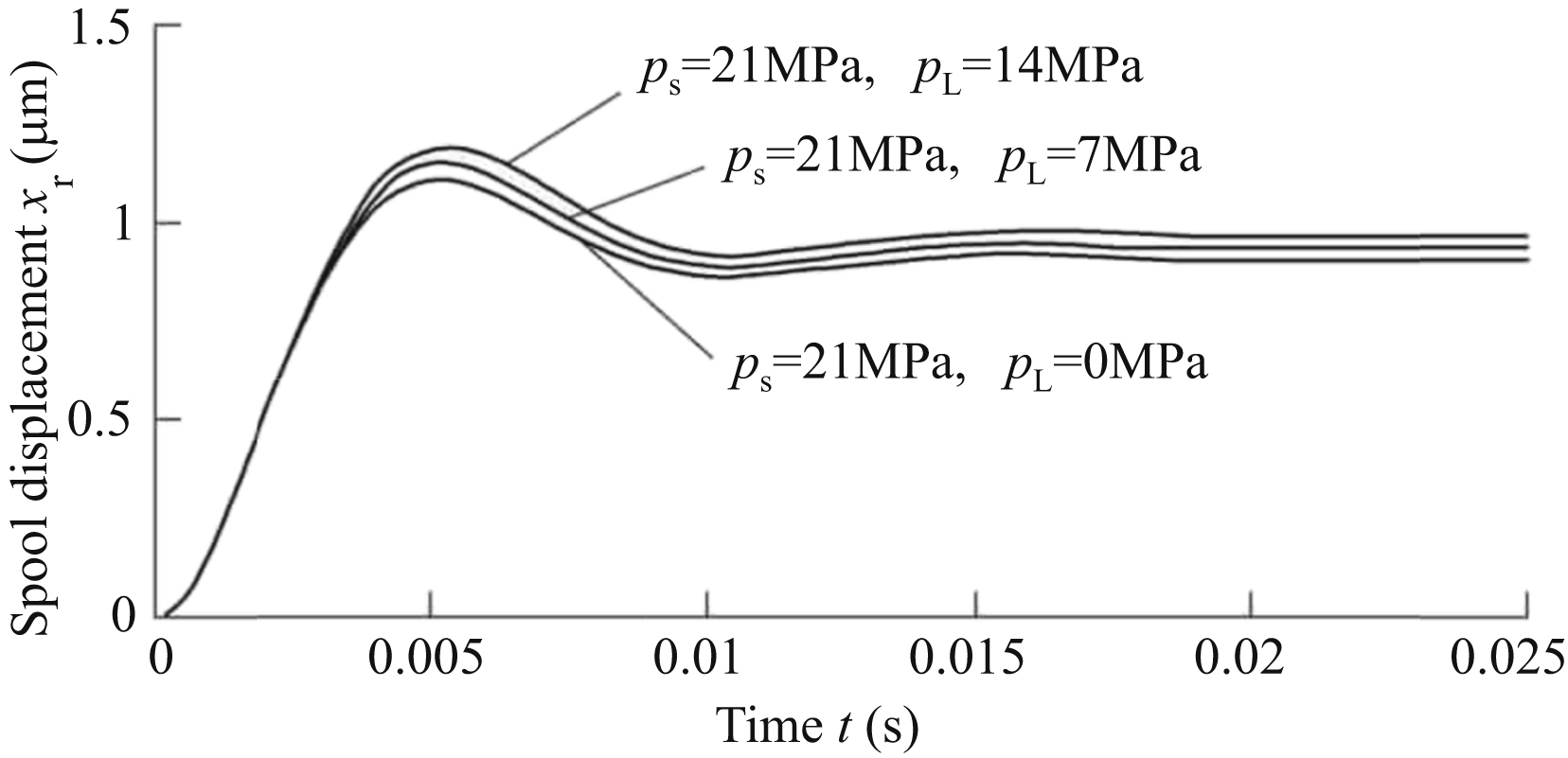
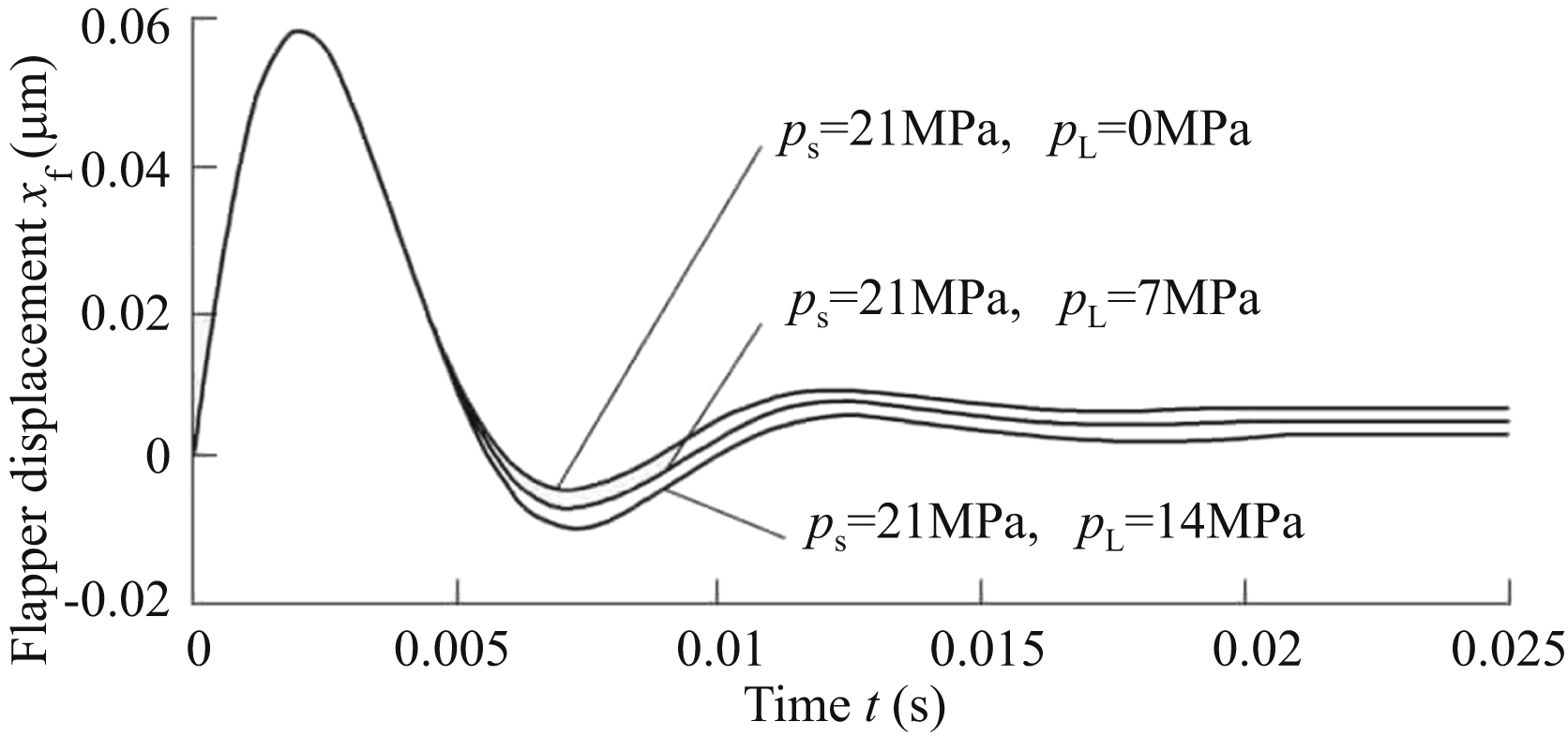
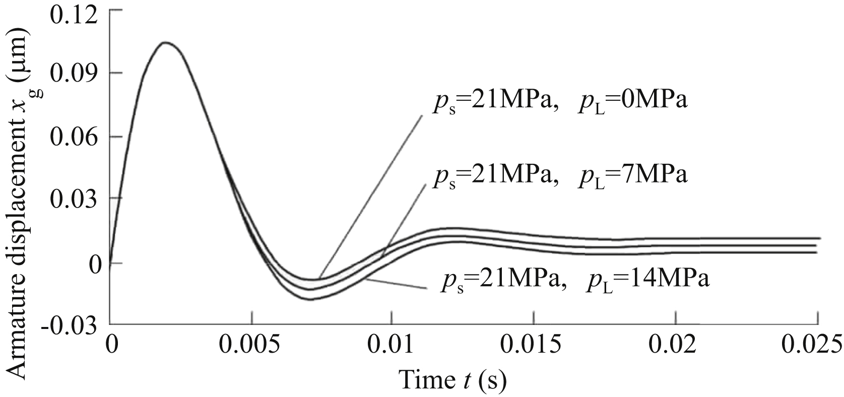
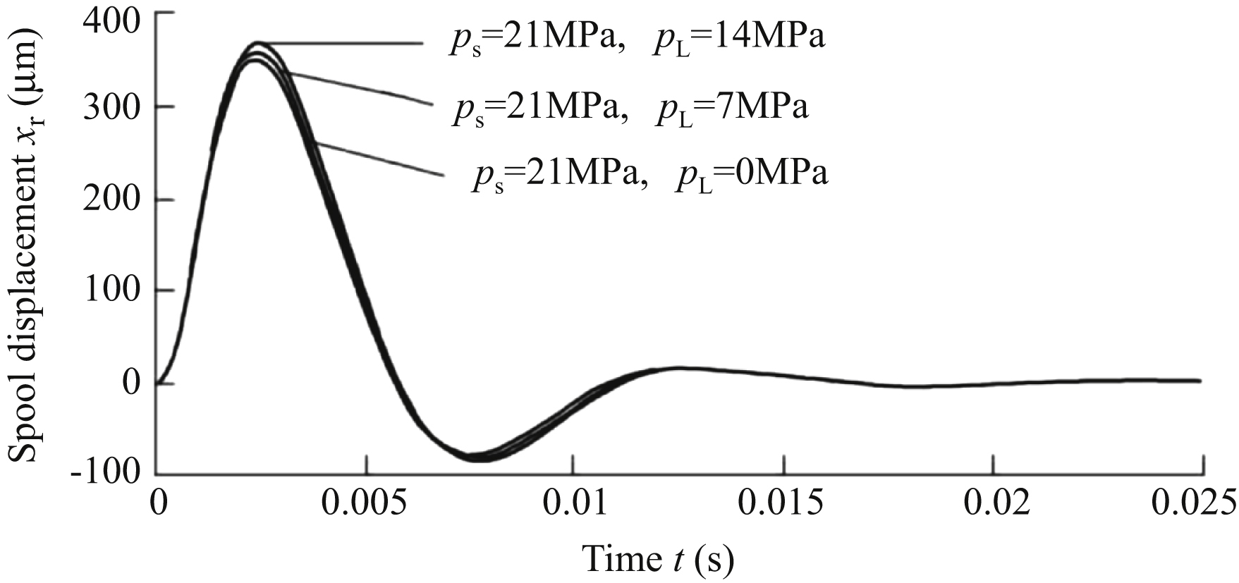
Assuming he supply pressure of an electrohydraulic servo valve is 21 MPa, no-load pressure and light load pressure 7 MPa and load pressure 14 MPa are respectively selected to compare with each other, and the change of displacement of three characteristic points at different load pressure is analysed. As shown in Fig. 11.2, in a valve body in a unit step acceleration environment, when supply pressure is constant, the smaller the load pressure,
the smaller the displacement of the slide valve. Sliding valve displacement increases steadily (10 ms) and then becomes stable. As shown in Figs. 11.3 and 11.4, in a unit step acceleration environment, when supply pressure is constant, the smaller the load pressure, the greater the displacement of the
flapper and armature. After displacement of the baffle and armature increases rapidly, it decreases rapidly (5 ms) and then becomes stable.
11.2.2. Influence of armature baffle assembly mass
There are many kinds of armature structure. Two kinds are widely used: flat arm (Fig. 11.5) and oblique arm (Fig. 11.6). The flat arm structure has good manufacturability and is easy to process; the oblique arm structure has better rigidity, but is difficult to process. Because of their different structures, the mass difference is significant; in two kinds of armature with the same arm length and arm, the latter is one-quarter to one-third lighter than the former. The baffle assembly also has a variety of structures, and its mass varies too. However, compared to the armature mass, the baffle assembly is of a smaller mass, and the ratio is about 1:10, so this aspect can be disregarded. The change of characteristic point displacement of the electrohydraulic servo valve is analysed when the mass of the armature baffle assembly is changed, so as to obtain anti-vibration measures.
For a valve body in a unit step acceleration environment, the greater the mass of the armature baffle assembly, the greater the displacement of the main spool valve, and the greater the displacement overshoot of the baffle and armature. In order to improve anti-vibration performance of an electrohydraulic servo valve, it is preferable to reduce the mass of the armature baffle assembly first. Simulation results show that displacement of the baffle and armature increases rapidly in a short time (5 ms), then decreases rapidly and becomes stable after a short period of time (about 15 ms).
11.2.3. Influence of main spool mass
When the valve body is subjected to unit step acceleration, the valve spool mass affects displacement of three characteristic points of the electrohydraulic servo valve. According to simulation results, when the valve body is
subjected to unit step acceleration, the change of the main slide value spool mass has almost no influence on sliding valve displacement, baffle displacement and armature displacement. The main reason for this is that the spool valve is in the power stage, and belongs to the control object of the pre-stage double nozzle flapper amplifier.

11.2.4. Influence of flexure tube stiffness
The flexure tube is an important part of the torque motor, and its stiffness affects characteristic point displacement of the electrohydraulic servo valve. Figs. 11.7–11.9 show that in a unit step acceleration environment, the greater the stiffness of a spring tube, the smaller the displacement overshoot of the spool valve core, the shorter the transition time, and the smaller the displacement overshoot of baffle and armature, and finally reach a stable state. Thus, the stiffness of the flexure tube mainly affects the overshoot of spool valve displacement, baffle plate displacement, armature displacement and transition time.


11.2.5. Influence of distance between centre of mass of armature baffle assembly and centre of rotation of flexure tube
Because the mass of the armature is much greater than the mass of the baffle, the centre of mass of the armature baffle assembly can be regarded as the centre of mass of the armature. In both the flat arm structure and the oblique arm structure, the armature is a regular symmetrical structure, and its centre of mass is its geometric centre. For the flexure tube, the armature is also a symmetrical structure with regular shape, and its rotation centre is its geometric centre. The distance between the centre of mass of the armature baffle assembly and the centre of rotation affects displacement of characteristic points of the electrohydraulic servo valve. In a unit step acceleration environment, reducing the distance between the centre of mass
of the armature baffle plate and the centre of rotation of the spring tube, displacement of main spool valve core can be effectively reduced. When stability is reached, x
r and d
e are approximately linearly related. Overshoot of baffle and armature displacement can be greatly reduced, and transition time is shortened.
Therefore, reducing the distance between the centre of mass of the armature baffle plate and the centre of rotation of the flexure tube can greatly reduce overshoot of slide valve spool displacement, baffle and armature displacement. It can also shorten transition time, and effectively improve anti-vibration characteristics of the electrohydraulic servo valve.
11.2.6. Influence of nozzle flapper amplifier control chamber volume
For the Moog31 electrohydraulic servo valve, the volume of the individual nozzle amplifier control chamber is about 47.4 mm3, which is full of hydraulic oil, and is equivalent to a ‘hydraulic spring’. In a unit step acceleration environment, the change of volume of the nozzle baffle amplifier control chamber has almost no influence on sliding valve displacement x
r, baffle displacement x
f and armature displacement x
g. The main reason for this is that the load pressure change rate of the nozzle flapper amplifier for controlling the valve spool is too small. Hydraulic fluid in the control chamber volume cannot be significantly compressed, and the stiffness of the hydraulic spring in this volume is relatively soft and thus has no effect.
11.3. Electrohydraulic servo valve in unit pulse acceleration environment
Taking unit pulse acceleration impact as input signal and valve displacement as output signal, this section analyses the influence of structural parameters on the response characteristics of the Moog31 force feedback electrohydraulic servo valve.
11.3.1. Influence of load pressure
Assuming the supply pressure of electrohydraulic servo valve is 21 MPa, no-load pressure and light load pressure 7 MPa and load pressure 14 MPa are selected to compare with each other, and the change of displacement of three characteristic points at different load pressures is analysed. As shown in Fig. 11.10, in the valve body in a unit pulse acceleration environment, the opening of the main slide valve opens a larger displacement (350 μm,
approximately designed maximum opening amount of spool valve) in a short time (2.5 ms); this may cause misoperation of follow-up actuator during actual operation. As shown in Fig. 11.11, unit pulse acceleration will cause a larger displacement of the baffle (45 μm), exceeding the original distance between the nozzle and baffle, indicating that basically the baffle is in contact with the nozzle. As shown in Fig. 11.12, unit pulse acceleration will cause larger displacement of armature (80 μm), close to one-third of the original distance of the armature air gap; this may cause the adsorption of armature and permeator. After oscillation of short duration (about 15 ms), sliding valve displacement x
r, baffle displacement x
f and armature displacement x
g tend to the zero position. When the load pressure changes, there is little difference in the oscillatory process of displacement between the three characteristic points.


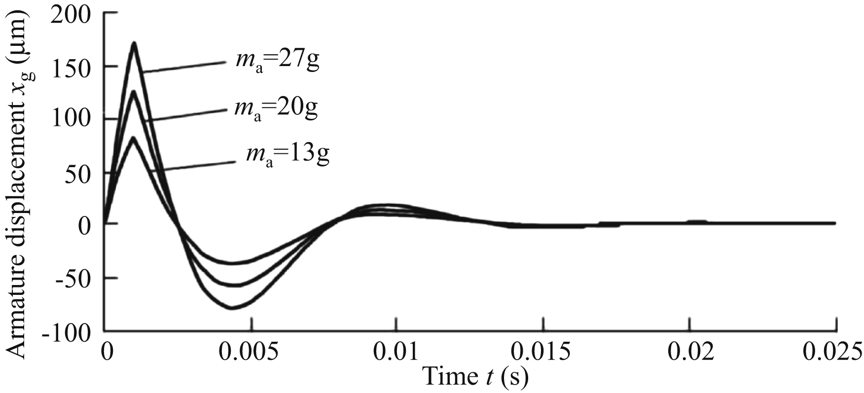
11.3.2. Influence of armature baffle assembly mass
Due to its difference in structure, the mass of the armature baffle assembly is different in different structure. In a unit pulse acceleration environment, the mass of different armature baffle assemblies has different effects on characteristic point displacement of the electrohydraulic servo valve. As shown in Figs. 11.13–11.15, in a unit pulse acceleration environment, when the mass of an armature baffle assembly increases, the maximum displacement of the main spool valve core, the maximum displacement of the baffle and the maximum displacement of the armature will increase accordingly. That is to say, the greater the mass of an armature baffle assembly, the greater the peak value of displacement of three characteristic points, and the increment of peak value is approximately linear with the increment of mass of the armature baffle assembly. For oscillation time, when the mass of the armature baffle assembly becomes larger, the oscillation times of three characteristic
point shifts vary little. Basically, after oscillation of about 15 ms, sliding valve displacement x
r, baffle displacement x
f and armature displacement x
g tend to the zero position.
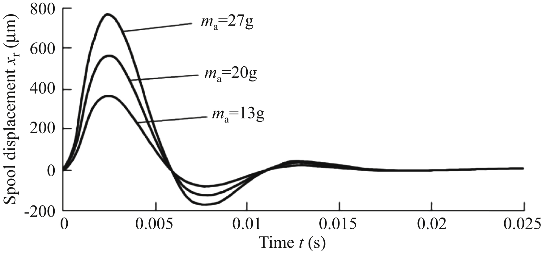

As mentioned above, by reducing the mass of the armature baffle assembly, the peak value of displacement of three characteristic points in unit pulse acceleration environment can be effectively reduced, thereby improving the impact resistance performance of the electrohydraulic servo valve. For example, in the same case using an oblique arm structure, compared to using a flat arm structure, has a better impact resistance. In general, material used for manufacturing armature is iron nickel soft magnetic alloy 1J50. If lighter density materials can be used to reduce the mass of armature baffle assembly, they can also improve the impact resistance performance of the electrohydraulic servo valve.
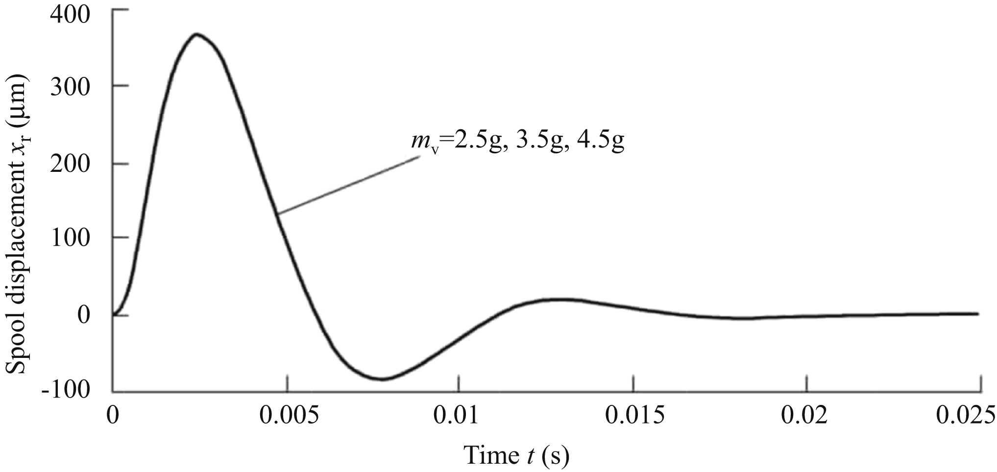
11.3.3. Influence of main spool mass
In a unit pulse acceleration environment, the change of the main slide value spool mass has almost no influence on sliding valve displacement x
r, baffle displacement x
f and armature displacement x
g. The main reason for this is that the spool valve is in power stage, and belongs to the control object of the pre-stage double nozzle flapper amplifier. As shown in Fig. 11.16, under the action of unit pulse acceleration, after the servo valve oscillates for a short time (about 15 ms), sliding valve displacement x
r, baffle displacement x
f and armature displacement x
g tend to the zero position.
11.3.4. Influence of flexure tube stiffness
The flexure tube is an important part of the torque motor, and its stiffness has a certain effect on the characteristic point displacement of the electrohydraulic servo valve. As shown in Fig. 11.17, in a unit pulse acceleration environment, when the flexure tube’s stiffness increases, the sliding valve spool displacement oscillation peak will be greatly reduced, and transition time will be shortened. It can be seen from Figs. 11.18 and 11.19, in a unit pulse acceleration environment, when spring tube stiffness increases, the flapper and armature displacement oscillation peak will be reduced, and transition time will be shortened. After a short period of oscillation, sliding valve displacement x
r, baffle displacement x
f and armature displacement x
g tend to the zero position.
It can be seen that under a unit pulse acceleration environment, by increasing the stiffness of the flexure tube, the oscillation peak value of
sliding valve displacement x
r, baffle displacement x
f and armature displacement x
g can be effectively reduced, thus improving the impact resistance performance of the electrohydraulic servo valve. Measures to increase the stiffness of the flexure tube can be derived from the following theoretical analysis.


A flexure tube is equivalent to a hollow cantilever beam, and its stiffness is calculated as follows:
where:
Through the above analysis, measures to increase the stiffness of the flexure tube are as follows:
- 1. On the premise of ensuring reliability and feasibility, flexure tubes are made of materials with larger modulus of elasticity.
- 2. It is designed to increase the cross-sectional moment of inertia of the flexure tube, such as increasing outer diameter or reducing inner diameter.
- 3. The effective length of the flexure tube is reduced.
Of course, the above measures can be adopted individually or several items can be used at the same time.
11.3.5. Influence of distance between centre of mass of armature baffle assembly and centre of rotation of flexure tube
Figs. 11.20–11.22 show that in a unit pulse acceleration environment, when the distance between the centre of mass of the armature baffle assembly and the centre of rotation of the flexure tube becomes larger, the maximum displacement of the main spool valve core, maximum displacement of the baffle and maximum displacement of the armature increase accordingly. The larger d
e is, the greater the peak value of those three, the greater the peak value of displacement of the three
characteristic points, and the increment of peak value is approximately linear with the increment of mass of the armature baffle assembly. The oscillation time of displacement of the three characteristic points has little change. After oscillation of about 15 ms, sliding valve displacement x
r, baffle displacement x
f and armature displacement x
g tend to the zero position.

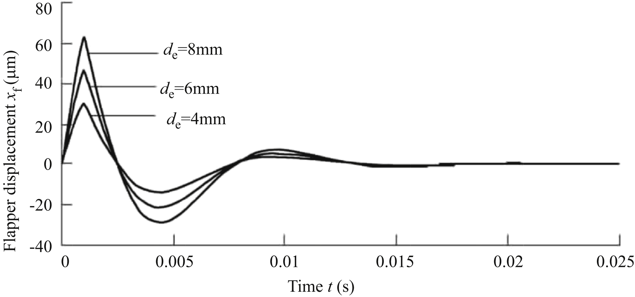
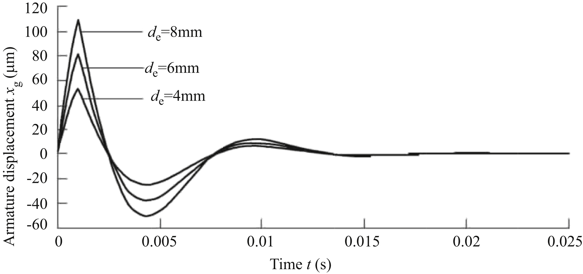
From the above, reducing the distance between the centre of mass of the armature baffle assembly and the centre of rotation of the flexure tube d
e can effectively reduce the peak value of the three characteristic points of the electrohydraulic servo valve, and improve the anti-impact characteristics of the valve.
11.3.6. Influence of nozzle flapper amplifier control chamber volume
Taking the Moog31 electrohydraulic servo valve as an example, the volume of the individual nozzle amplifier control chamber is about 47.4 mm3, and hydraulic oil in this chamber is equivalent to a ‘hydraulic spring’. The stiffness of the hydraulic spring is relatively soft. In a unit pulse acceleration environment, the change of volume of the nozzle baffle amplifier control chamber has almost no influence on sliding valve displacement x
r, baffle displacement x
f and armature displacement x
g.
11.4. Electrohydraulic servo valve under vibration condition
The frequency response characteristic of the force feedback electrohydraulic servo valve under a vibration signal is analysed, including load pressure p
L, armature baffle assembly mass m
a, mass of main spool m
v, rigidity of spring tube K
a, distance between centre of mass of armature baffle assembly and centre of rotation of spring tube d
e, volume of single control chamber of nozzle flapper amplifier V
0p and other parameters. The variation characteristics of sliding valve displacement x
r, baffle displacement x
f and armature displacement x
g are analysed.
11.4.1. Influence of various parameters on frequency response of slide valve displacement
When parameters such as p
L, m
a, m
v, K
a, d
e and V
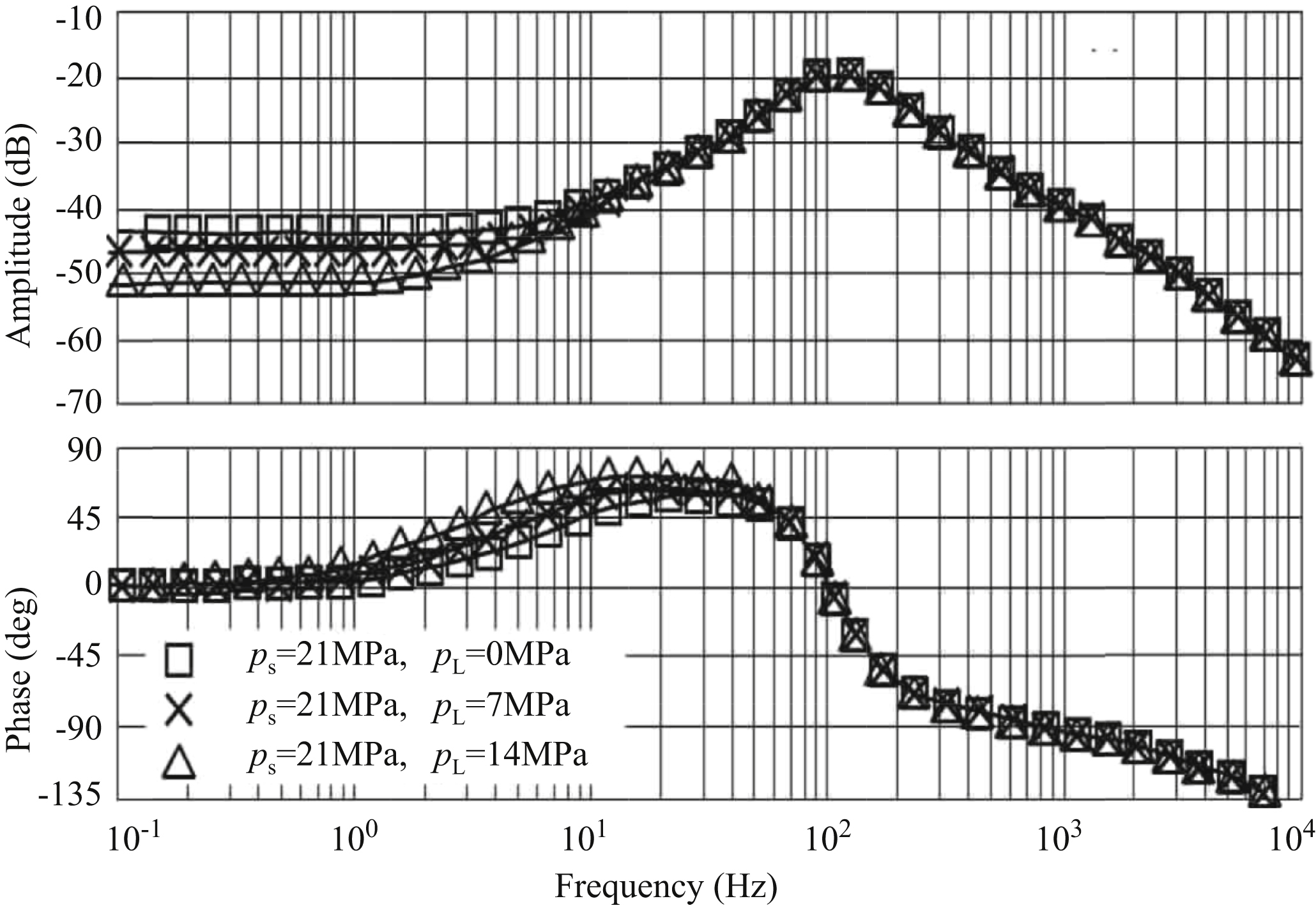
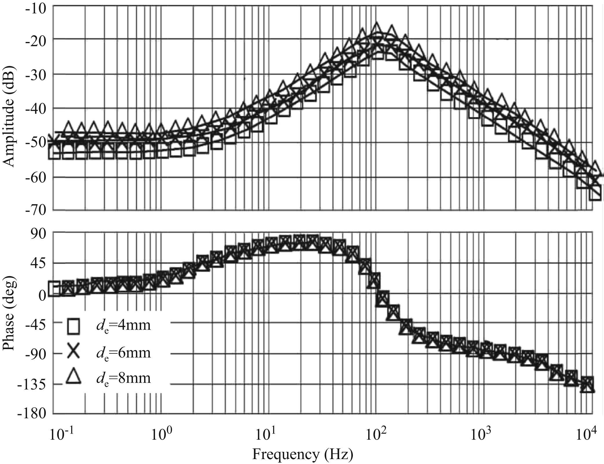
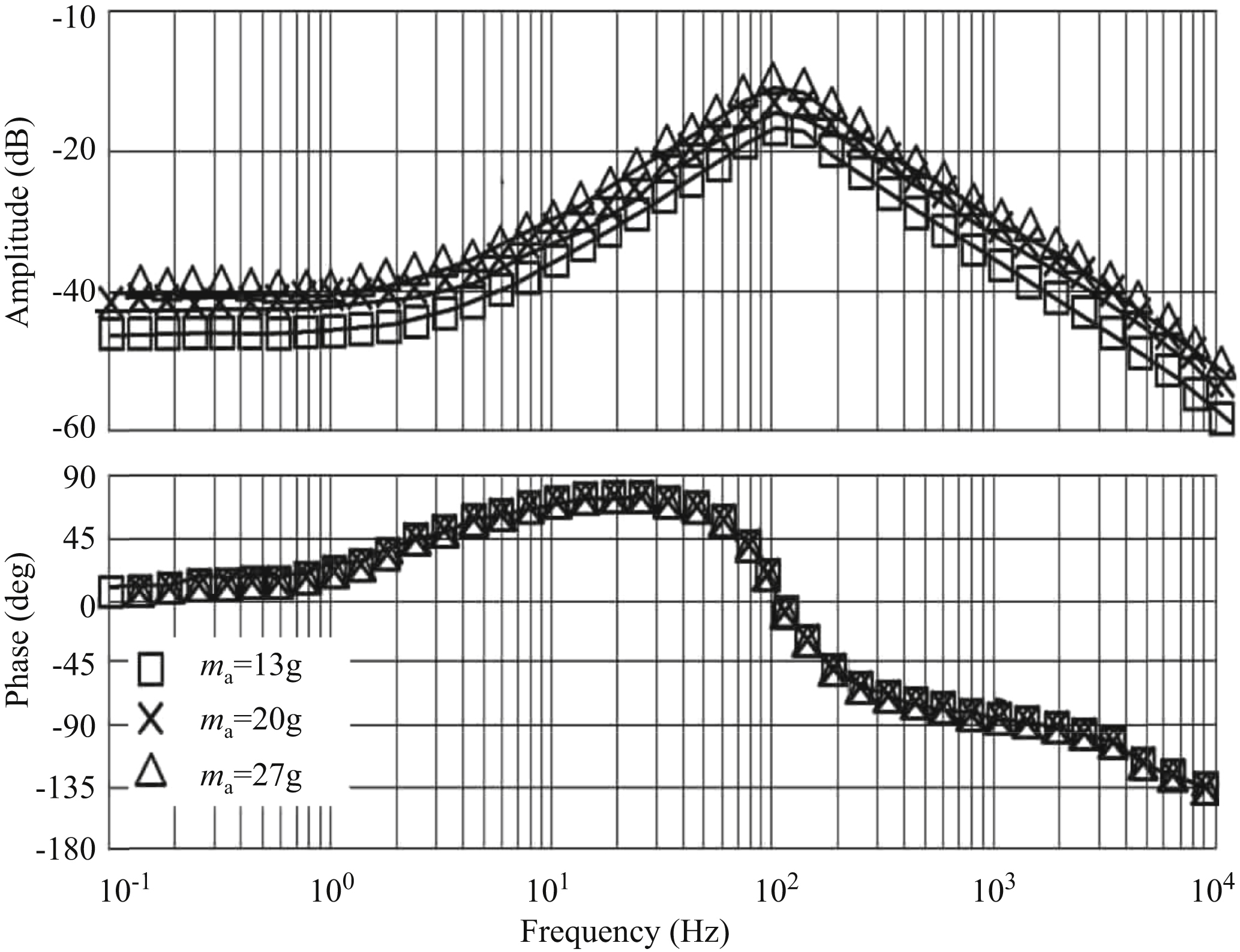
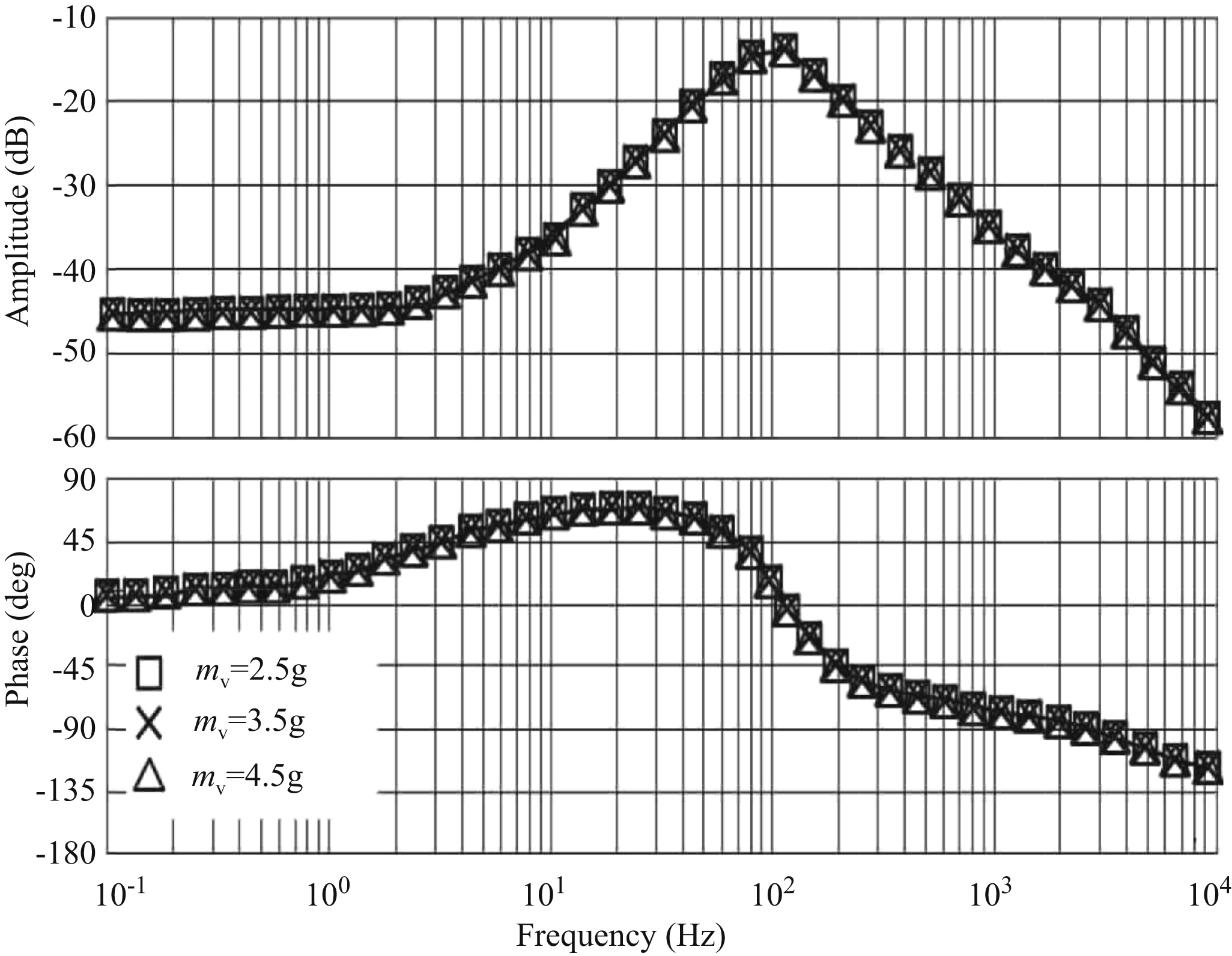
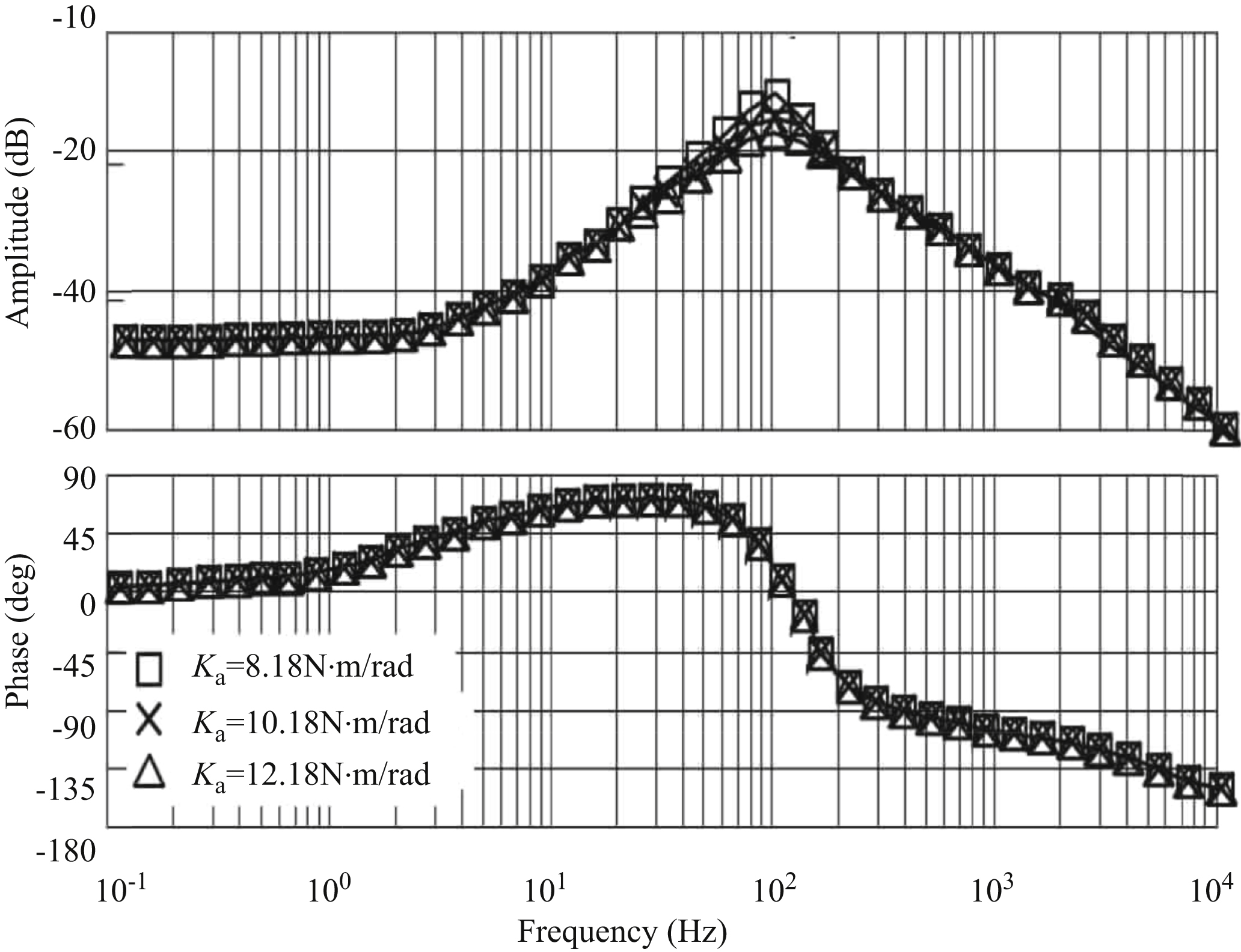
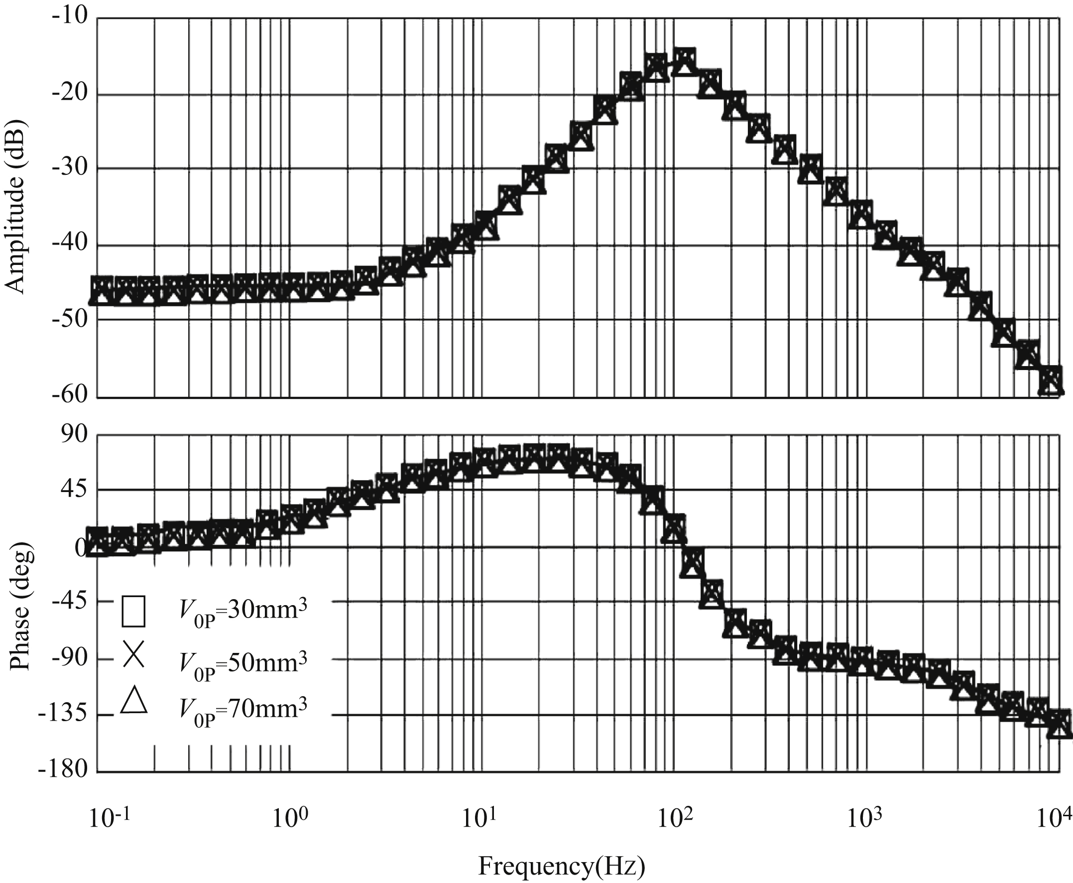
0p are different, the frequency response of the main spool displacement to a vibration signal is also different. As shown in Figs. 11.23–11.28, slide valve displacement is
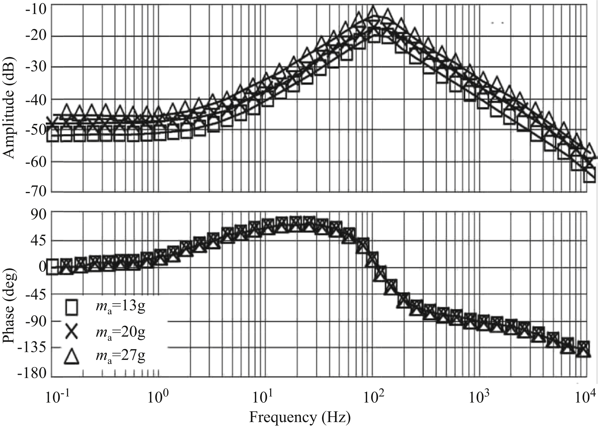
sensitive to low frequency vibration signal (<150 Hz). When the vibration signal is about 90 Hz, the amplitude frequency gain is the largest, and resonance occurs. As shown in Fig. 11.23, the load pressure changes slightly affect the amplitude frequency characteristics of sliding valve displacement to vibration signal – that is, the higher the load pressure, the smaller the amplitude frequency gain. The change of load pressure has little influence on the force feedback electrohydraulic servo valve’s phase frequency characteristics. From Figs. 11.24 and 11.27, an increase of the armature baffle assembly, and an increase of distance between the centre of mass of the armature baffle assembly and the centre of rotation of the spring tube will increase amplitude frequency gain of sliding valve displacement to vibration signal. It was also verified in the first two sections of this chapter that the displacement overshoot of the sliding valve increases and the oscillation peak increases when m
a and d
e increase. However, when m
a and d
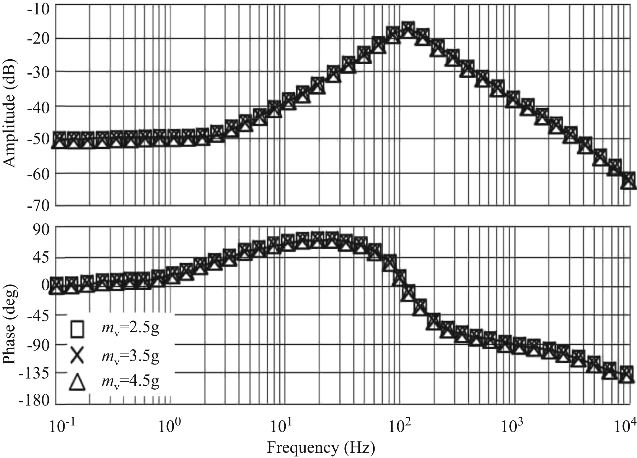
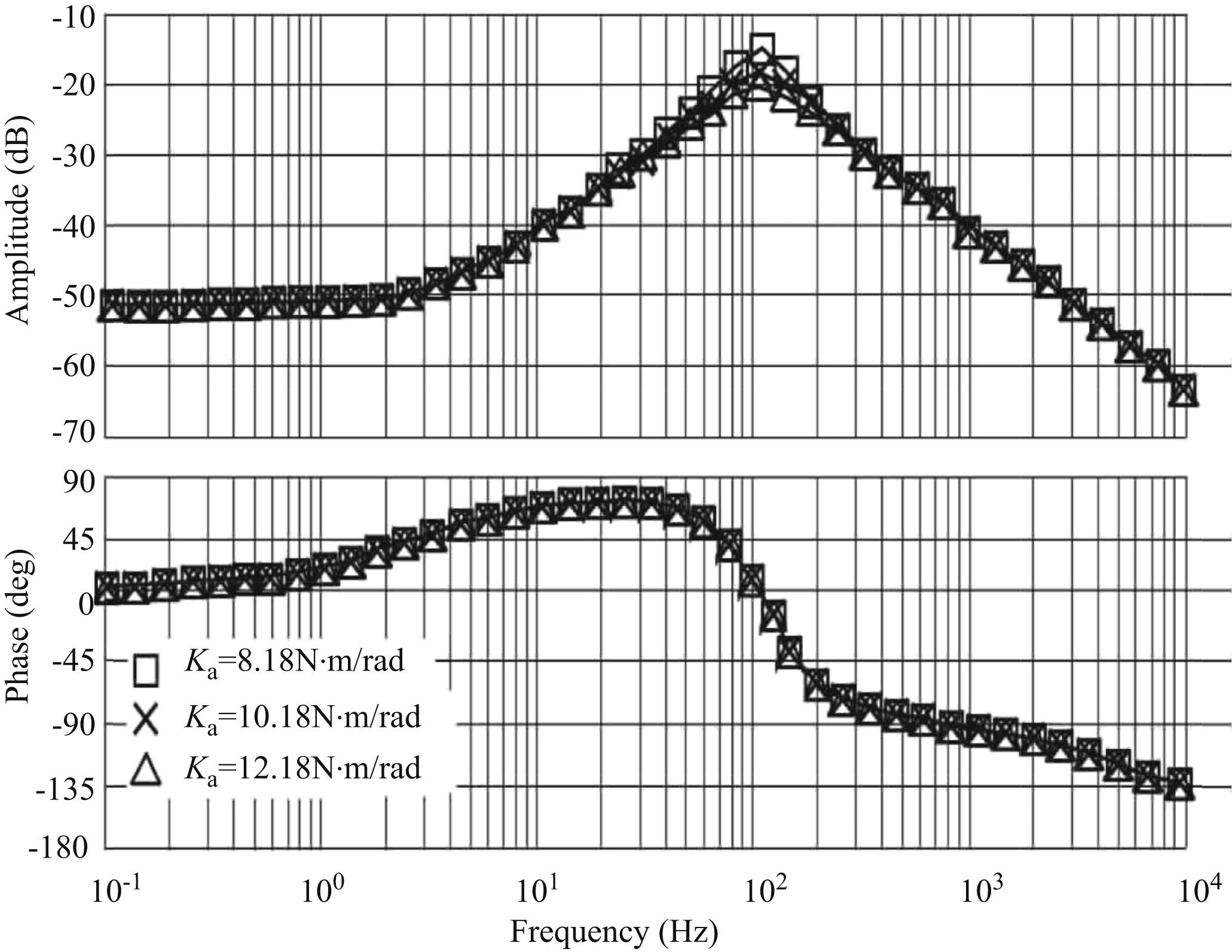
e are increased, amplitude frequency width and the phase frequency characteristic of slide valve displacement to the vibration signal are not affected. As shown in Figs. 11.25 and 11.28, a change of mass of the valve core and volume of the nozzle baffle amplifier control chamber do not affect amplitude frequency characteristics and phase frequency characteristics of the valve opening to vibration signal. As shown in Fig. 11.26, an increase of stiffness of the spring tube will reduce the peak value of the amplitude frequency gain of sliding valve displacement to the vibration signal and reduce its amplitude frequency width, but increase its phase frequency width. It was also verified in the first two sections of this chapter that the displacement overshoot of the sliding valve increases and the oscillation peak increases when K
a increases.


11.4.2. Influence of various parameters on frequency response of baffle displacement
The frequency response of baffle displacement to the vibration signal is analysed when parameters such as p
L, m
a, m
v, K
a, d
e and V
0p change. As shown in Figs. 11.29 and 11.34, baffle displacement is sensitive to wide frequency vibration signal (0–2000 Hz). When the vibration signal is about 100 Hz, the amplitude frequency gain is at its largest, and resonance occurs. As shown in Fig. 11.29, when the load pressure increases, amplitude and frequency gain of baffle displacement to vibration signal will be reduced when the vibration signal frequency is less than 10 Hz; when the vibration signal frequency is less than 40 Hz, the phase advance angle of baffle displacement to the vibration signal will increase. In addition, an
increase of load pressure will increase the amplitude frequency width of baffle displacement to the vibration signal. From Figs. 11.30 and 11.33, the increase of the armature baffle assembly, and the increase of distance between the centre of mass of the armature baffle assembly and the centre of rotation of the spring tube will increase the amplitude frequency gain of baffle displacement to the vibration signal – that is, the displacement overshoot of the baffle increases and the oscillation peak increases when m
a and d
e increase. However, when m
a and d
e are increased, the amplitude frequency width and phase frequency characteristic of baffle displacement to the vibration signal are not affected. As shown in Figs. 11.31 and 11.34, the change of mass of the valve core and volume of the nozzle baffle amplifier control chamber do not affect amplitude frequency characteristics and phase frequency characteristics of baffle displacement to the vibration signal. As shown in Fig. 11.32, an increase of stiffness of the spring tube will reduce the peak value of the amplitude frequency gain of baffle displacement to the vibration signal and reduce its amplitude frequency width, but increase its phase frequency width. That is, the displacement overshoot of the baffle increases and the oscillation peak increases when K
a increases.

11.4.3. Influence of various parameters on frequency response of armature displacement
The frequency response of armature displacement to the vibration signal is analysed when parameters such as p
L, m
a, m
v, K
a, d
e and V
0p change. As shown in Figs. 11.35 and 11.40, armature displacement is sensitive to a wide frequency vibration signal (0–2000 Hz). When the vibration signal is about 100 Hz, the amplitude frequency gain is at its largest, and resonance occurs. As shown in Fig. 11.35, when the load pressure increases, the amplitude and frequency gain of armature displacement to the vibration signal will be reduced when the vibration signal frequency is less than 10 Hz; when the vibration signal frequency is less than 40 Hz, the phase advance angle of armature displacement to the vibration signal will increase. In addition, an increase of load pressure will increase the amplitude frequency width of armature displacement to the vibration signal. From Figs. 11.36 and 11.39, an increase of the armature baffle assembly and an increase of distance between the centre of mass of the armature baffle assembly and the centre of rotation of the spring tube will increase the amplitude frequency gain of armature displacement to the vibration signal. That is, the displacement overshoot of armature increases and the oscillation peak increases when m
a
and d
e increase. However, when m
a and d
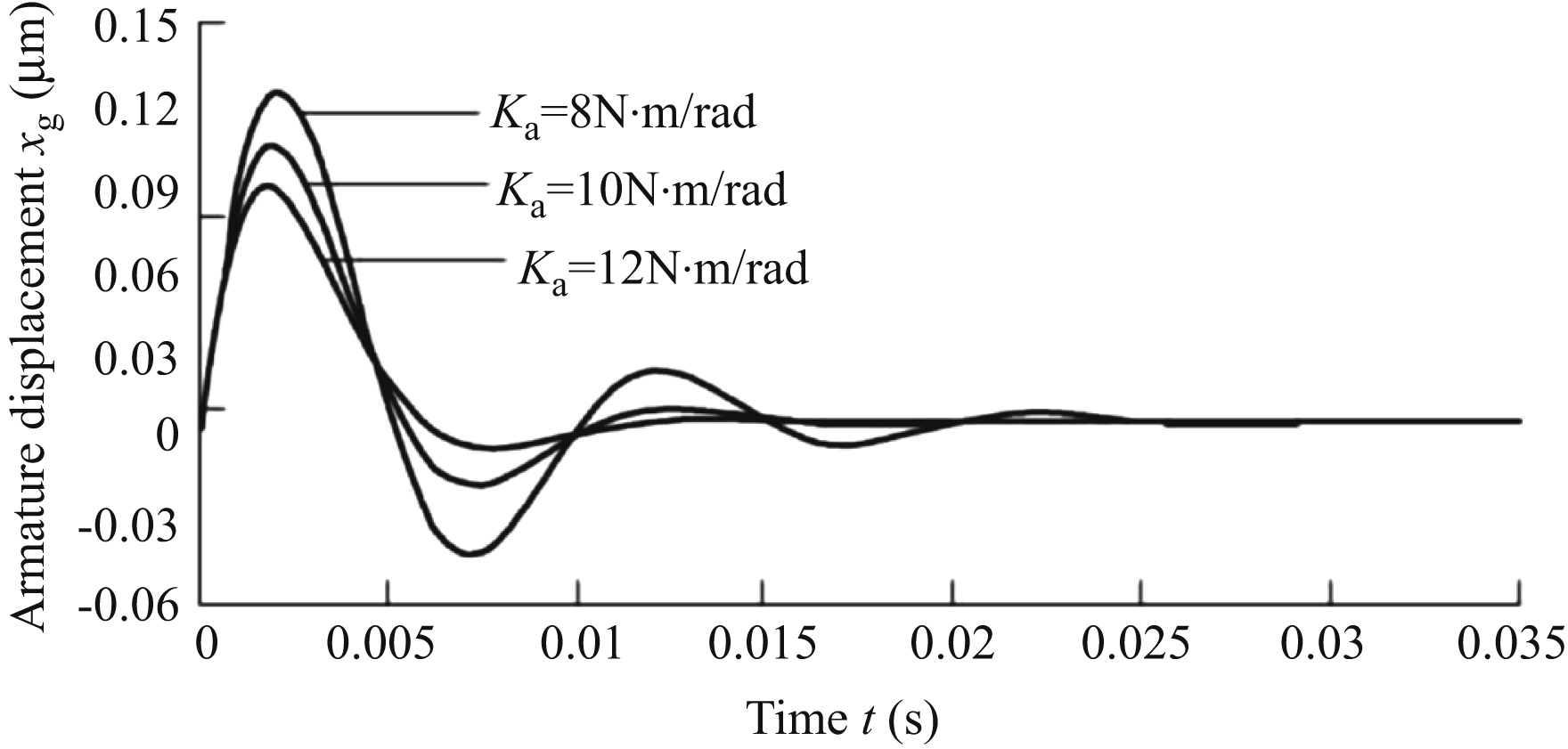
e are increased, the amplitude frequency width and phase frequency characteristic of armature displacement to the vibration signal are not affected. As shown in Figs. 11.37 and 11.40, a change of mass of the valve core and volume of the nozzle baffle amplifier control chamber do not affect the amplitude frequency characteristics and phase frequency characteristics of armature displacement to the vibration signal. As shown in Fig. 11.38, an increase of stiffness of the spring tube will reduce the peak value of the amplitude frequency gain of armature displacement to the vibration signal and reduce its amplitude frequency width, but increase its phase frequency width. That is, the displacement overshoot of the armature increases and the oscillation peak increases when K
a increases.


11.5. Conclusions
11.5.1. Anti-impact measures of electrohydraulic servo valve
Taking Moog31 electrohydraulic servo valve data as an example, the effects of an impact environment on the performance of a electrohydraulic servo valve is mainly shown in the following two aspects:
- 1. An acceleration environment mainly affects the opening of the main spool. In a unit step acceleration environment, the main valve spool will eventually open a displacement about 0.97 μm; the baffle will show a displacement of about 0.0028 μm, and the armature will show a displacement of about 0.005 μm.
- 2. In an impulse acceleration environment, an opening peak value about 350 μm of main valve opening in a short period of time (about 2.5 ms) will appear, approximately the maximum spool opening, is likely to cause misoperation of subsequent mechanism in system; the baffle will have an opening peak value of about 45 μm in a short time, and the nozzle is in contact with the baffle; the armature in a short time will appear about 80 μm opening peak, close to the margin of safety, that is, one-third the original gap of the armature air gap, there may have armature and magnet attracting, causing electrohydraulic servo valve failure; after a short period of oscillation (about 15 ms), the three characteristic points shift back to zero.
In order to improve the impact resistance of the electrohydraulic servo valve, the main measures are as follows:
- 1. Reduce the mass of the armature baffle assembly – for example, for the armature, compared with a plain arm structure, an inclined arm structure can effectively reduce armature mass.
- 2. Reduce the distance between the centre of mass of the armature baffle assembly and the centre of rotation of the spring tube. Because the mass of the armature baffle assembly is mainly concentrated on the armature, this plus the baffle plate and spring tube are rigidly connected at the top of the spring pipe, and the centre of mass of the armature baffle assembly is at the end of the spring pipe. The spring tube is equivalent to a hollow cantilever beam whose rotation centre is its geometric centre. The distance between the centre of mass of the armature baffle assembly and the centre of rotation of the spring tube can be effectively reduced by reducing the length of the spring tube.
- 3. Increasing the stiffness of the spring tube. This can be achieved by increasing the outer diameter of the spring tube, reducing its inner diameter, or by other measures.
11.5.2. Influencing factors of the electrohydraulic servo valve in vibration environment and vibration control measures
The factors influencing the performance of the electrohydraulic servo valve in a vibration environment and measures of vibration resistance are as follows:
- 1. Displacement of the main valve is sensitive to vibration signals at low frequency (<150 Hz). When a vibration signal is about 90 Hz, the amplitude frequency gain is at its largest, and resonance will occur.
- 2. The armature is rigidly connected with the baffle, and displacement of the armature and baffle is consistent with the frequency characteristic of the vibration signal. Both are sensitive to vibration signal of wider frequency (0–2000 Hz). When the vibration signal is about 100 Hz, the amplitude frequency gain is at its largest, and resonance occurs.
- 3. When the vibration signal frequency is in the range of 90–100 Hz, the performance of the electrohydraulic servo valve is most affected. Measures should be taken to improve the installation conditions of the electrohydraulic servo valve.
..................Content has been hidden....................
You can't read the all page of ebook, please click here login for view all page.