Chapter 13
Optimal Design of the Electrohydraulic Servo Valve
In the design and analysis of the electrohydraulic servo valve, how to ensure the speediness and stability of this valve and optimize its index parameters are issues of great importance. In this chapter, the optimization analysis method of the electrohydraulic servo valve is obtained from two aspects: amplitude margin and torque motor stiffness. The amplitude margin affects stability and rapidity of force the feedback electrohydraulic servo valve. Firstly, the relationship between bandwidth, phase margin and amplitude margin is analysed by frequency characteristics of the electrohydraulic servo valve. How to optimize structure and performance parameters of the electrohydraulic servo valve is discussed from the aspect of the amplitude margin. The concept of relative frequency amplitude ratio is introduced, and the frequency characteristic of the electrohydraulic servo valve and method of determining stiffness of the torque motor are put forward. An optimal design method based on composite stiffness of the electrohydraulic servo valve torque motor is put forward. This involves a design concept of relative frequency amplitude ratio and relative bandwidth of the electrohydraulic servo valve torque motor. By using a relation of relative frequency amplitude ratio, relative bandwidth, amplitude margin and phase margin, optimal design of integrated stiffness of the electrohydraulic servo valve torque motor can be achieved.
This chapter introduces a new type of electrohydraulic servo valve with a restrictor at both ends of the main spool, and introduces its specific structure and characteristics in detail. Combined with asymmetry of structure in engineering practice, the characteristics of the electrohydraulic servo valve with symmetrical and asymmetrical nozzle baffle initial clearance, symmetrical and asymmetrical nozzle diameter are analysed. At the same time, a new type of single-stage electrohydraulic servo valve with a restrictor in its nozzle chamber is proposed. By means of model test data and experimental phenomena, an optimized design method is verified. Aiming at problems found in the test process, measures of vibration control
are proposed and verified. The asymmetric structure of the electrohydraulic servo valve nozzle flapper valve explains phenomena in use and test of the electrohydraulic servo valve to some extent.
13.1. Optimal design of the electrohydraulic servo valve based on amplitude margin
By analysing the relationship between frequency characteristics and their bandwidth, the phase margin and amplitude margin of the electrohydraulic servo valve, we discuss how to optimize structure and performance parameters of the electrohydraulic servo valve from the view of the amplitude margin. Firstly, the relation between bandwidth, phase margin and amplitude margin of the force feedback electrohydraulic servo valve is analysed. The family of curves of bandwidth ratio and amplitude margin relation, and the family of curves of phase margin and amplitude margin relation of the electrohydraulic servo valve at different damping ratios, are obtained. Methods and procedures of how to use these two typical curve family graphs to optimize the design of synthetic stiffness and structural parameters of the torque motor are given when design and stability analysis of the electrohydraulic servo valve is carried out. Theoretical results and simulation results are compared and analysed.
13.1.1. Theoretical analysis
I. Fundamental equations
When analysing the mathematical model of the electrohydraulic servo valve, it is assumed that the main valve of the electrohydraulic servo valve is ideal zero lap and four-way slide valve, without taking into account internal leakage.
1. Flow linear equation of dual nozzle baffle to the left and right chambers of the main spool
where:
- K qp is the flow gain of load port of the nozzle flapper valve;
- r is the distance from the nozzle bore centre to the centre of rotation of the armature;
- θ is the rotation angle of the armature;
- K cp is the pressure-flow coefficient of the nozzle flapper valve load port;
- Q Lp is the flow generated by the left and right chamber load ports when the main spool moves; and
- P Lp is the load pressure difference at both ends of the main spool.
2. Flow balance equation of left and right chambers of the main valve core when the main spool moves
where:
- A v is the cross-sectional area of the main spool;
- x v is the displacement of the main spool;
- C tp is the total leakage coefficient of the nozzle flapper valve, because leakage of the compensating cavity is very small, so C tp = 0;
- β is the coefficient of elasticity of the oil; and
- V op is the volume of the chamber composed of the nozzle, main valve core and fixed throttling device when the valve core is in the middle position.
3. Force equilibrium equation of the main spool
where:
4. Moment equilibrium equations of the armature assembly
where:
- K t is the torque constant of the torque motor;
- i is the input current of the torque motor;
- J a is the moment of inertia of the armature and its load;
- B a is the viscous damping coefficient of mechanical support and load of the armature;
- K mf is the composite stiffness of the torque motor;
- A N is the nozzle hole area;
- b is the distance from nozzle hole to the centre of the spool; and
- Kan is the net stiffness of the armature baffle.
II. Frequency characteristics
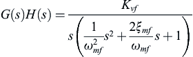
Considering the fundamental equations of (13.1)–(13.5) and simplifying, the open loop transfer function and closed loop transfer function from input signal control current to output signal spool displacement of the electrohydraulic servo valve are obtained, respectively:
 (13.6)
 (13.7)
where:
- G(s) is the front channel transfer function of the electrohydraulic servo valve;
- H(s) is the feedback loop transfer function of the electrohydraulic servo valve;
- K vf is the speed amplification factor;
- ω mf is the natural frequency of the torque motor;
- ξ mf is the damping ratio of the torque motor; and
- G B (s) is the closed loop transfer function.
and:
From Eq. (13.6), the amplitude frequency characteristic of open loop transfer function can be obtained:
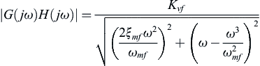 (13.11)
where:
The phase frequency characteristic of the open loop is:
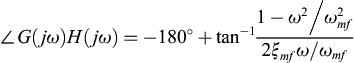 (13.12)
From Eq. (13.12), the phase crossing frequency can be obtained:
The amplitude margin of the electrohydraulic servo valve is:
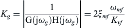 (13.14)
According to the definition of amplitude bandwidth, the amplitude bandwidth of closed loop transfer function shown in Eq. (13.7) should satisfy the following expression:
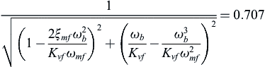 (13.15)
Substituting Eq. (13.14) into Eq. (13.15), the following equation can be obtained after arranging:
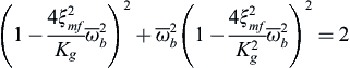 (13.16)
Eq. (13.16) represents the relationship between the amplitude margin and bandwidth ratio of the electrohydraulic servo valve at a given damping ratio. A series of curves between the bandwidth ratio and amplitude margin can be obtained when different damping ratios are taken. As shown in Fig. 13.1, the starting point of each curve is determined by the stability condition. According to the Routh-Hurwitz criterion, the stability condition for a closed loop transfer function as shown in Eq. (13.7) is:
Substituting Eq. (13.14) into Eq. (1.18), the amplitude margin constraint can be obtained as: K
g>1 – that is, abscissa of each curve in Fig. 13.1 must be greater than 1.
From Eq. (13.6), the expression of shear frequency of the open loop transfer function can be obtained:
 (13.19)

When shearing frequency is substituted into Eq. (13.12), the phase margin expression can be obtained:
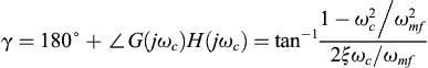 (13.20)
 (13.21)
 (13.22)
where
 is the relative shear frequency.
Eq. (13.22) represents the relation between amplitude margin and phase margin of the electrohydraulic servo valve at a given damping ratio. When the damping ratio is different, a series of relation curves of phase margin and amplitude margin can be obtained by Eqs. (13.21) and (13.22), as shown in Fig. 13.2.
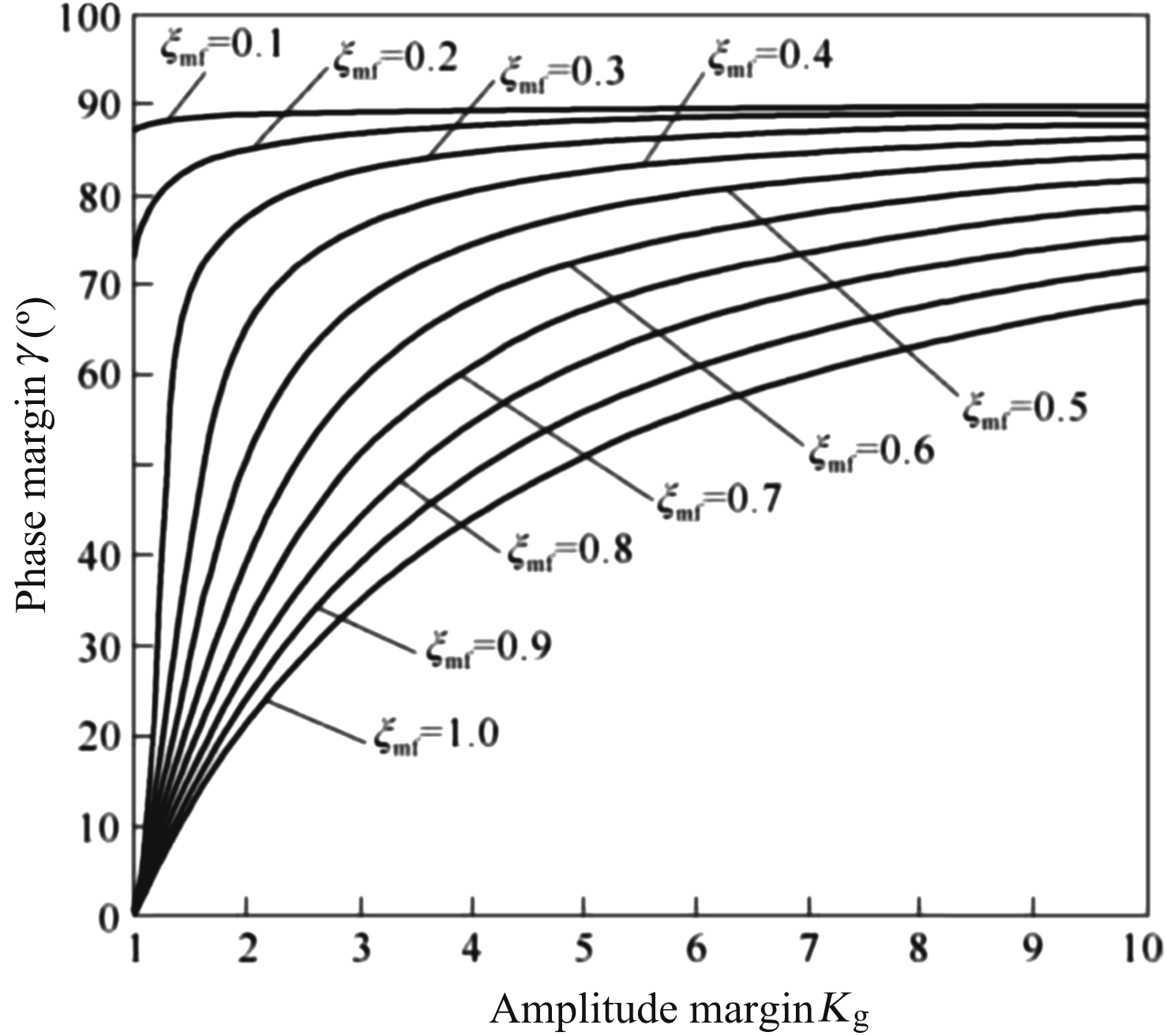
13.1.2. Optimal design
I. Parameter optimization design
In order to give the electrohydraulic servo valve a satisfactory stability margin, it is generally hoped that: g = 30°–60°, K
g>2. Taking the electrohydraulic servo valve torque motor integrated stiffness optimization design as an example, in design and stability analysis of the electrohydraulic servo valve, the above stability principle and two typical curve families can be used. The optimal design steps can then be described as follows:
- 1. Determine the magnitude of the damping ratio of the torque motor. The proper amplitude margin is selected by looking at curve family of phase margin and amplitude margin relation shown in Fig. 13.2.
- 2. The corresponding bandwidth ratio can be obtained by looking at the curve family of bandwidth ratio and amplitude margin relation shown in Fig. 13.1.
- 3. The amplitude margin and bandwidth ratio are substituted into Eqs. (13.14) and (13.17) respectively, and the integrated stiffness optimization parameters and corresponding bandwidth of the torque motor are obtained.
- 4. By using the Double Sides Approximate Process method, several steps are followed to obtain the optimal combination relationship of the torque motor stiffness parameters, bandwidth and stability.
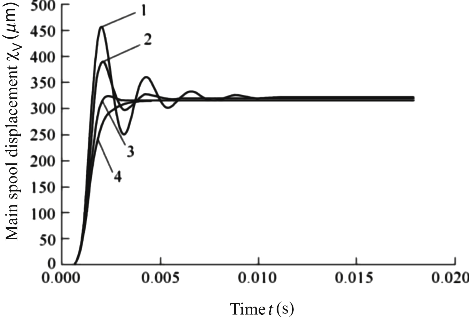
II. Simulation analysis
Through the fundamental equations of (13.1)–(13.5), nonlinear simulation model of the electrohydraulic servo valve is established by using SIMULINK, which uses the control current as input signal and displacement of the main spool as output signal. In the case of the other parameters being unchanged, from the point of view of the amplitude margin, the stiffness of the torque motor is changed, and step response curve of the main spool displacement at a different amplitude margin is obtained.
Fig. 13.3 shows step response curves of valve displacement when the damping ratio ξmf is 0.07 and the amplitude margin K
g is 2,3,5,7. Mathematical simulation results show that determination of the amplitude margin index has a great influence on rapidity and stability of the electrohydraulic servo valve. Combined with theoretical analysis results, it is helpful to optimize structural parameters of the electrohydraulic servo valve by using the relationship of amplitude margin and bandwidth ratio and phase margin.
..................Content has been hidden....................
You can't read the all page of ebook, please click here login for view all page.