
Chapter 14
Marine Hydraulic Technology
14.1. Hydraulic system of ship pitch propeller
A ship propeller converts the energy of a ship’s main engine into kinetic energy of the ship. As shown in Fig. 14.1, when the main engine drags the propeller to rotate at an angular speed w, the propeller pushes water aside from the left of the vessel in the direction of the ship, so the ship gets a thrust p that moves it to the right.
In order to throw water more effectively to produce greater thrust, the blade of the propeller must have a spiral surface. Thus, the intersection of the cylindrical surface that is coaxial with the propeller and blade of propeller in Fig. 14.1F is a spiral line. If a triangle with a base of 2pr and height of H
1 as shown in Fig. 14.1G is rolled on a cylindrical surface with a radius of r, the bevel edge of this triangle becomes the helix shown in Fig. 14.1F. H
1 and q1 are called the pitch and helix angles of this helix, respectively.
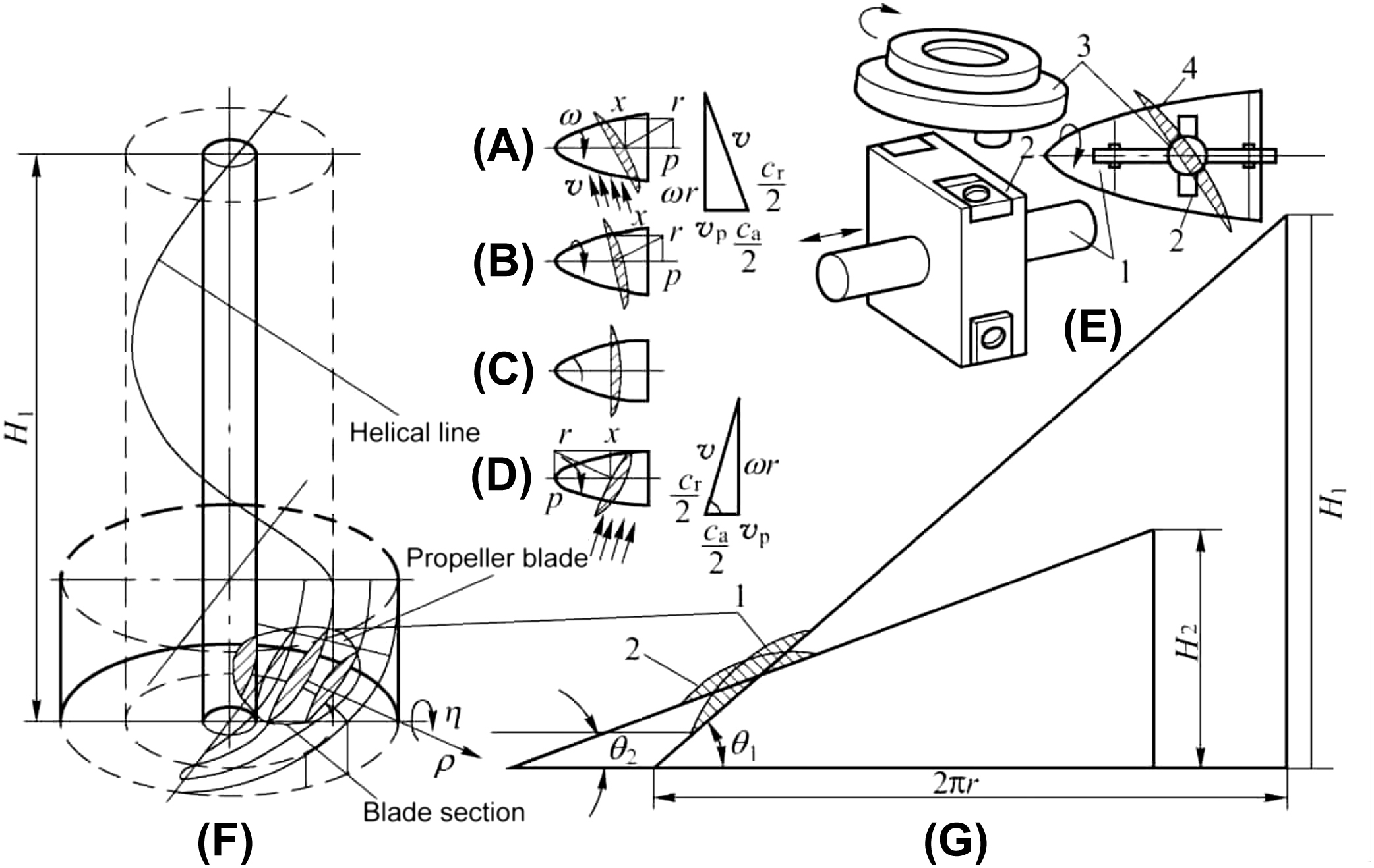
In Fig. 14.1F, the cross section of blade cut by a cylindrical surface that is coaxial with the propeller is known as the section of blade. Some blades in propellers can regulate their rotation around propeller shaft r. Before and after rotation, if the cylinder surface with a radius of r opens into a plane, then the blade profile is as shown in Fig. 14.1G 1, 2. Comparison shows that the pitch is transferred from H
1 to H
2, and the pitch angle is transferred from q1 to q2. The name pitch propeller is derived from this.
As shown in Fig. 14.1E, the slider crank mechanism is a commonly used rotary vane mechanism. When push rod 1 moves along an axial direction, slide block 2 is driven to slide in the groove, then slider 2 drives crank 3 and the blade connected with crank 3 to rotate around the propeller shaft by a pin shaft to adjust the pitch of the blade. When the paddle is adjusted to the states shown in Fig. 14.1A, B, C and D, the corresponding speed of the ship is forward, decelerate, stop and retreat. The above characteristics of the pitch propeller give it the following main advantages:
- 1. Under any navigation condition, the power of the main engine can be fully utilized, so as to improve the endurance of the ship.
- 2. Under the condition that the direction and speed of main engine are constant, the pitch propeller can change the ship’s navigational state by adjusting the pitch. Thus, time and distance needed to change the sailing state of the ship are shortened, and the manoeuvrability of the ship is significantly improved.
- 3. When the ship changes navigational state, the speed and steering of the main engine can be completely unchanged. Therefore, the starting and speed regulation of the main engine can be reduced significantly, thus prolonging the life of the main engine.
- 4. After a pitch propeller is used, if the ship uses a diesel engine as its main engine, the whole set of reversing equipment can be omitted; if a gas turbine is used as the main engine, there is no need to set up a separate reversing engine. As a result, automation of the main engine control is easy to implement.
The disadvantage is that the mechanism is complex, and thus brings with it a series of problems. These must be dealt with in the design of a hydraulic system.
The requirements of a hydraulic system for a pitch propeller are as follows:
- 1. The vitality of the power unit requires that the hydraulic system of a pitch propeller takes adequate technical measures to satisfy it. For example, to solve whole-ship power failures, control failures and other serious failures, generally a number of energy sources are adopted. In addition, mutual interference between energy sources and safety protection devices should also be set up.
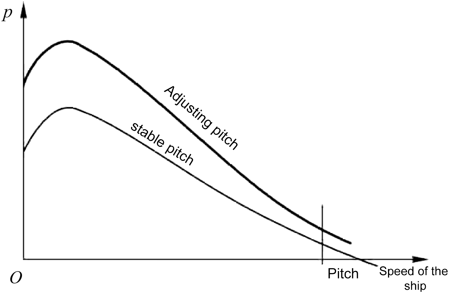
- 2. The hydraulic system of a controllable pitch propeller is a larger power system on a ship, and the external load varies greatly. As shown in Fig. 14.2, system pressure is relatively high when pitch is changed, and the pressure is low when pitch is stable, especially when the speed is normal, oil pressure is approaching zero. When the pitch is adjusted, the pump output is large, but when the pitch is stable, the pump is only need to make up for the system leak. Therefore, the unloading circuit needs to be set up to reduce power loss and oil heating of the system.
- 3. When the blade is adjusted to the required pitch, it should be able to be ‘locked’ in order to achieve a ‘stable pitch’, so a locking circuit should be set. When the blade goes from positive pitch to zero pitch, the hydrodynamic moment is active torque (negative torque condition), which should be able to prevent the blade’s over-speed rotation around the propeller shaft.
- 4. In order to reduce the mass and size of a system (especially the size of propeller housing), most hydraulic systems adopt middle and high pressure, so it is necessary to solve some technical problems of the large-diameter high-speed rotary joint.
- 5. There are some certain requirements for pitch range, time and accuracy of pitch propeller.
In addition to the above, the system hydraulic shock should be small, able to prevent infiltration of sea water into propeller shell, easy to maintain and economical. In addition, a spiral angle indicator should be set.
The hydraulic system of a pitch propeller is the same as the hydraulic system of a steering engine; there are also open type, closed type, open loop and closed loop. Usually a closed loop system is used. The following sections analyse two typical pitch propeller hydraulic systems.
14.1.1. Open system
Fig. 14.3 shows an open hydraulic system of a pitch propeller. This open system was introduced from KAMEWA, Sweden. The system diagram is shown in Fig. 14.3A. The actual screw angle q2 controlled by pitch hydraulic cylinder 15 is compared with the required spiral angle q1 of main command after feedback, and converts to voltage signal u
q, which reflects the error of helix angle q1 – q2. After the voltage signal u
q is amplified by phase sensitive rectification, the commutation and opening size of proportional electromagnetic reversing valve 8 can be controlled, so as to control the positive and negative pole of spiral angle and the pitch speed of the controllable pitch propeller.
For example, a handle is used to turn a potentiometer to an angle in a certain direction. If there is an error between the desired spiral angle and the actual spiral angle – that is, an error signal u
q with a certain polarity is input to the system – then the proportional electromagnet D2 of valve 8 inputs current I
2 corresponding to u
q. Valve 8 is shifted to the right and opened in proportion to I
2, and the oil discharged by pump a1 and a2 enters the right chamber of cylinder 15 by the right side of valves 8, 10 and 14. The return oil in the left chamber of cylinder 15 passes through valve 9 and the right side of valve 8 to the fuel tank. The piston rod of pitch adjusting cylinder 15 extends out to push the push rod of the rotary vane mechanism in Fig. 14.1E, causing the blades to rotate around the propeller shaft until the blade is adjusted to the desired helix angle q1. The error signal u
q then disappears, valve 8 is returned to the middle position and valve 14 locks the right chamber of pitch hydraulic cylinder 15 to maintain a stable pitch.
In Fig. 14.3, valve 13 is used to detect the control pressure of the pitch cylinder. The working pressure of the pitch cylinder in a stable pitch is lower; the maximum is 3 MPa. Therefore, the control oil pressure of controlled pump a1 and a2 is low, and pump a1 and a2 work at a small output to supplement the need of adjustable pitch cylinder leakage. When adjusting distance, the working pressure of cylinder 15 is higher, and the
maximum is 7.5 MPa. At this time, the higher control pressure makes pump a1 and a2 reach the maximum output to meet the need of rapid regulation. Therefore, the system is a flow adaptive system with less energy loss.
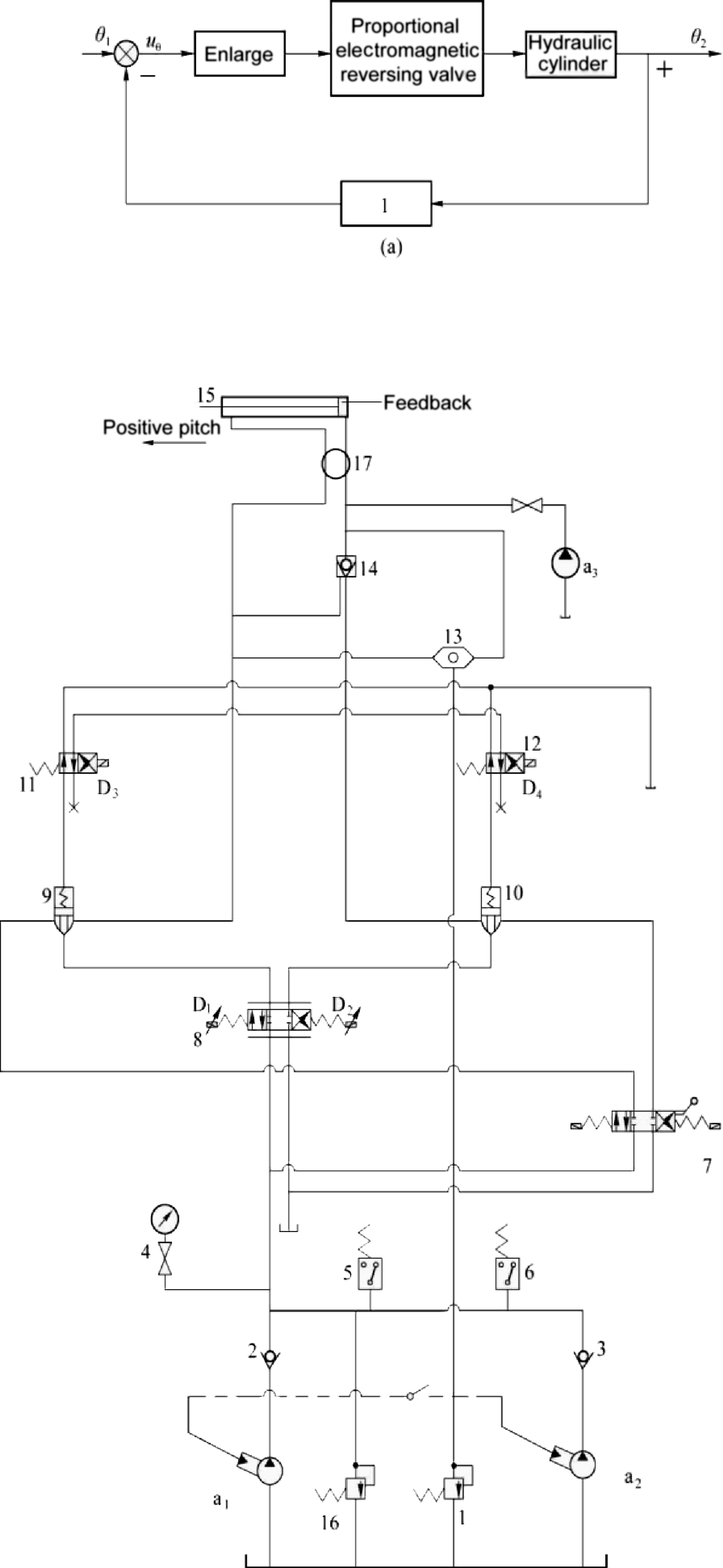
When the pitch is fixed, hydraulic control check valve 14 is used to lock the right chamber of cylinder 15. If the pitch is stable for a long time, the blade spiral angle decreases due to the leakage of pressure oil of the right cylinder chamber, valve 8 reversing to right place, then pump a1 and a2 with small flow through the right side of valve 8 fills the right chamber of the cylinder with oil.
The system uses redundancy design, and the reliability of the system is relatively good. Even if pump a1 or a2 is damaged, the system can still work; one-way valves 2 and 3 are used to prevent two pumps’ interference. If proportional electromagnetic directional valve 8 is damaged, as long as electromagnet D3 and D4 are powered, then valves 9 and 10 are closed, and valve 7 is in control. When the electromagnet of valve 7 is damaged, valve 7 can also be manually controlled. When the whole system is damaged, the distance-measuring oar can be adjusted to a positive pitch by hand pump a3. Valve 16 serves as a relief valve for the system, and valve 1 is a safety valve for pump a1 and a2 variable control loop. Valves 1and 16, shuttle valve 13 and valves 9 and 10 are all plug-in, being plugged into the same cartridge valve block. Valves 7and 8 and pressure relays 5 and 6 are all plate type connected, and are also arranged on the surface of the plug valve block. Therefore, the degree of integration of this system is very high.
14.1.2. Closed system
Fig. 14.4 shows a double pitch propeller closed hydraulic system with closed loop control. The working principle of one hydraulic system of the pitch propeller is analysed below.
Hydraulic oil discharged by auxiliary pump C1 and C2 is divided into three routes: one is used to control the variable mechanism of main pump A1, A2 and A3; one fills oil through one-way valve 1 or 2 to the low-voltage side of the main circuit; and the left one overflows through relief valve 8, then back into the tank after travelling through the pump housing of the main pump to cool the main pump. Valve 8 is used to adjust the working pressure of the auxiliary pump.
When a polar error signal is input, solenoid valve 10 reverses to the left. Oil discharged by the auxiliary pump enters cylinder 12 through valve 10, and causes the variable mechanism of pump A1 to deflect from the zero
position to another direction. In this way, oil discharged by the right chamber of pump A1 is divided into two routes: one into the small chamber of cylinder B1; and the other shoulders open valve 5 through the control oil circuit of hydraulic control check valve 5 (dotted line in figure), thus return oil of cylinder B1 large cavity, except for pump A1 oil absorption, excess oil can flow back to tank through valve 5 and back pressure valve 7. The rod of cylinder B1 moves to the right to adjust the pitch. When the propeller blade reaches the desired pitch, the error signal disappears, valve 10 returns to the middle position and the spring in cylinder 12 causes the variable mechanism of main pump A1 to return to the zero position. At this point, pump A1 is equivalent to a stop valve to maintain the pitch.

In negative moment conditions, pump A1 is in the hydraulic motor condition. It drags the propeller rotation along with host of dragging main pump, to avoid paddle over speed rotation around propeller shaft. This is also called ‘regeneration speed limit’, and system efficiency is high.
One-way valves at auxiliary pump C1 and C2 outlet are used to prevent the two pumps from interfering with each other. One-way valves 3 and 4 and overflow valve 6 form a bidirectional safety valve together. When main pump A1 or A2 fails, main pump A3 can be used instead. When solenoid valve 10 fails, manual reversing valve 11 can be used for emergency operation. Therefore, the reliability of the system is relatively great.
14.2. Ship accumulator-pump hydraulic energy system
14.2.1. Alternate operation of ship accumulator and pump hydraulic energy system
Due to the large number of actuators, the load of a ship’s hydraulic system varies widely. In order to reduce displacement of the hydraulic pump and reduce the power of the motor, the hydraulic system of a piston type pneumatic accumulator pump is often adopted, and an accumulator is used as an auxiliary hydraulic source to supply oil to the system. That is to say, the hydraulic system of a ship usually adopts a hydraulic energy system with a piston pneumatic accumulator and pump alternately working. When the accumulator discharges all the oil, the hydraulic pump starts with pressure to carry oil charging to the accumulator. After the accumulator is filled with oil, the hydraulic pump is changed from its working state with pressure to a state of unloading or stopping. At this point, the inlet pressure of hydraulic pump outlet one-way valve is lost, and pressure at the outlet side still exists
under accumulator pressure. As a result, a great pressure difference is formed at both ends, so that the valve port is rapidly switched from an open state to a closed state, and a large hydraulic impact is generated during the closing of the valve opening, resulting in a decrease in the overall performance of the system.
In order to reduce or eliminate system pressure impacts, it is common practice to install a bladder accumulator for pressure buffering near the pressure impact point. However, because of the charging and discharging function of the bladder accumulator, it is easy for this to oscillate repeatedly after absorbing pressure. To solve this problem, the accumulator pump hydraulic system increases a one-way throttle valve in the access section of the bladder accumulator. In this way, oil can smoothly enter the accumulator chamber when absorbing pressure impact, while the hydraulic oil return in the bladder is limited by throttling damping, and does not oscillate.
14.2.2. Principle of pressure buffering for ship accumulator-pump hydraulic system
A ship piston type pneumatic accumulator pump hydraulic system mainly consists of a screw pump, check valve, piston type pneumatic accumulator, overflow pipe and user line. In order to facilitate analysis, the system is simplified as a single pump and a single accumulator, as shown in Fig. 14.5A. The accumulator supplies oil to the system user at work, and the hydraulic pump is in an unloading or stopping state. When the accumulator discharges all the oil, the hydraulic pump starts with pressure to carry oil charging to the accumulator. After the accumulator has filled with oil, the upper travel switch of the accumulator will act and send a “ready” signal to the electric control box. The hydraulic pump is changed from its working state with pressure to a state of unloading or stopping. At this point, the pressure at both ends of the one-way valve on the hydraulic pump outlet line changes dramatically, resulting in a large hydraulic impact at the outlet of the one-way valve.
The bladder accumulator divides the shell by a leather bladder into two chambers of gas and liquid. The bladder is filled with nitrogen, and the bladder and shell form chambers filled with hydraulic oil. When added to the one-way valve outlet, the volume of gas in the bladder decreases with the increase of pressure, thereby absorbing the impact of the hydraulic energy and reducing or eliminating the pressure impact of the system. Fig. 14.5B shows a schematic diagram after adding t bladder accumulator.
Fig. 14.5C shows a schematic diagram of a one-way throttle valve on the access pipe section of a bladder accumulator.
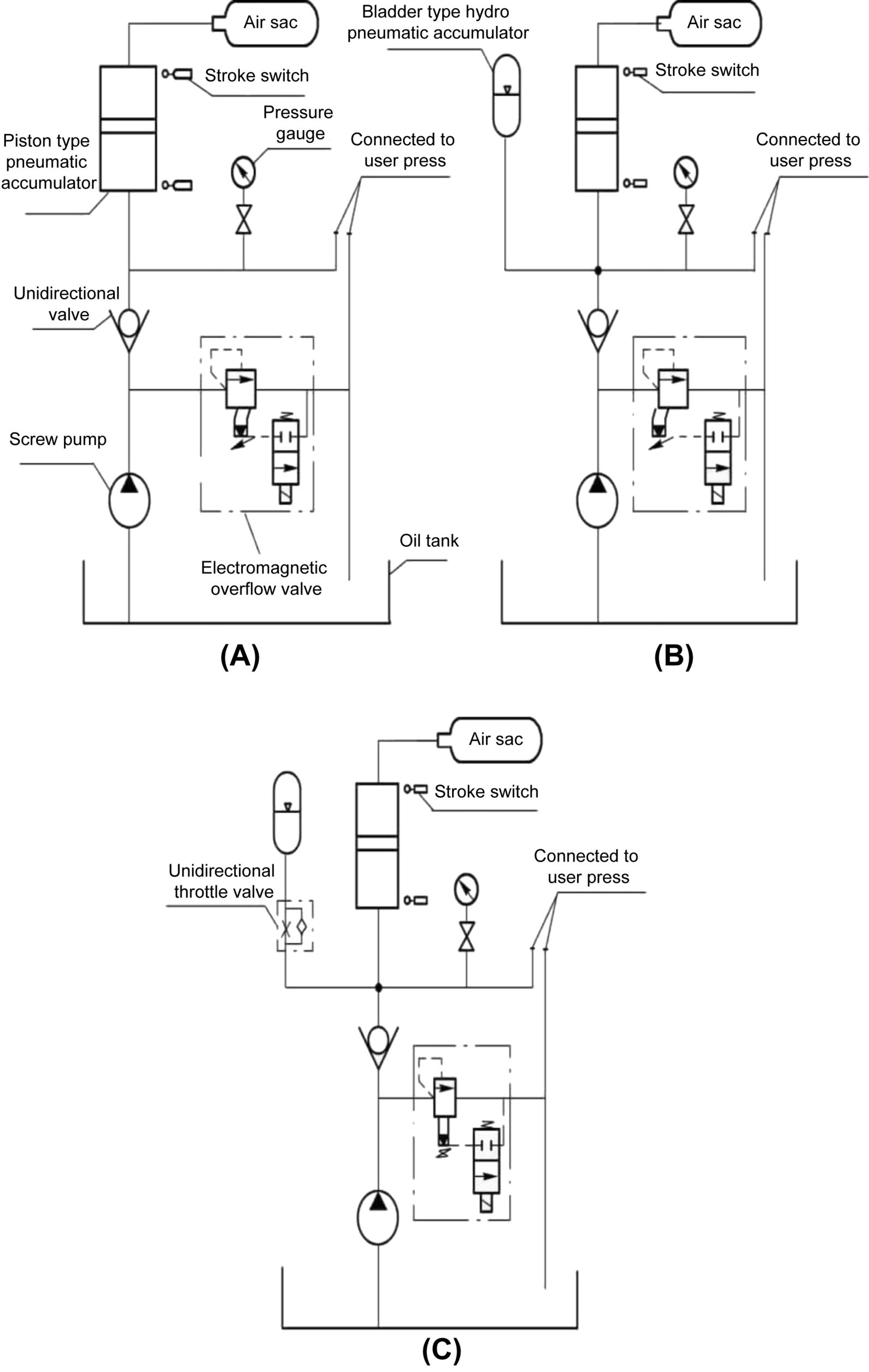
For a ship piston type pneumatic accumulator-pump hydraulic system, when the system is working normally, the working pressure is 10 MPa, the charging pressure of the accumulator is 8 MPa, the mass of the accumulator piston is 40 kg, the accumulator piston stroke is 0.98 m and the electric relief valve opening pressure is 12.5 MPa. In the absence of a bladder accumulator, when a piston type pneumatic accumulator filled with oil, the hydraulic pump outlet relief valve is energized when unloading. Due to the recoil effect of the oil pressure in the piston type pneumatic accumulator, the minimum value of check valve outlet pressure is 7.5 MPa, the maximum value is 12.9 MPa and the peak value of shock wave reaches 5.4 MPa. A bladder accumulator with a one-way throttle valve is added. After adjusting the opening of one-way throttle valve properly, the minimum value of outlet pressure of the one-way throttle valve is 8.7 MPa, the maximum value is 12 MPa and the peak value of shock peak is decreased to 3.3MPa; 61% of the bladder accumulator is without a one-way throttle valve.
14.3. Dynamic pressure damper technology
The electrohydraulic servo valve system has a low frequency and relatively small damping coefficient of hydraulic machinery integrated resonance; this seriously affects the stability of a system. To improve stability, a method of improving a system’s structure resonance frequency and hydraulic natural frequency can be adopted. However, the former involves significant change of the mechanical structure, which causes the volume and mass of the structure to increase greatly. It is bulky and uneconomical, and the increase of structure resonance frequency is very limited. Although the latter is easier to improve, the resonant frequency of the system is often lower than that of the natural frequencies of heavy equipment in a ship. This means that the structural resonance becomes the main factor affecting synthetic resonance of hydraulic machinery. At this point, even if the natural frequency of a system is increased, synthetic resonance frequency cannot be significantly improved, so as to improve the stability of a system.
Because a hydraulic servo system has low damping problems, the simplest and most economical way is to improve system damping. For example, in a valve-controlled hydraulic cylinder system, the relative damping coefficient is below 0.2, while a pump-controlled hydraulic
cylinder is less damped and sometimes less than 0.005, so the relative damping coefficient is tried to improve the stability of a system. Although there are many ways to increase dynamic pressure damping of a system, the most direct method is mechanical dynamic pressure feedback. Its advantage is that it has nothing to do with the dynamic performance of a pump control device and electrical control system. It can effectively improve the hydraulic damping ratio of system, improving the stability and bandwidth of the system.
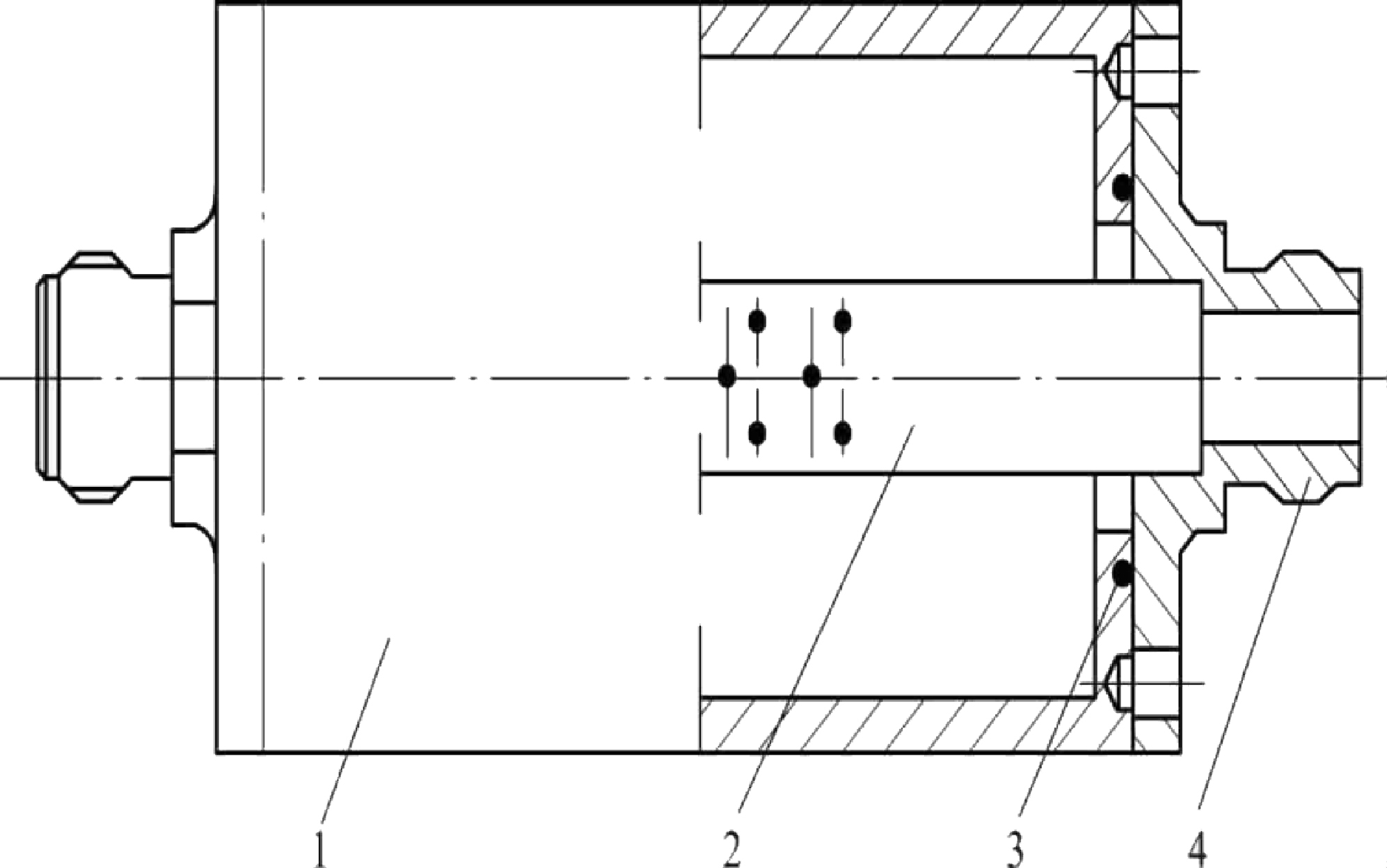
14.3.1. Structure and working principle of dynamic pressure damper
A dynamic pressure damper consists of a shell, end cap, throttling damper, spring and isolating plunger (Fig. 14.6). The working principle of dynamic pressure damper is shown in Fig. 14.7. When the pump control device is connected to an input signal, the flow enters the dynamic pressure damping chamber to form pressure, while the other chamber pressure decreases (or does not change, because oil is supplied by the supply pump). If the two chamber pressures change rapidly, the hydraulic cylinder piston and its transmission will be impacted. The hydraulic oil in the two chambers of hydraulic cylinder becomes oil liquid spring, and a mechanical spring is formed from the transmission device, great mass of inertia formed by pistons, transmission, etc. When the damping of the two cavities and transmission are not enough, the system becomes a spring and an oscillating part. Under the action of impact force, the system will produce resonance or vibration, which will affect the system’s performance and reliability.
When a dynamic pressure damper is added, two cavity pressure difference feedback is added, so that part of the oil in the pump input cavity enters the dynamic pressure damping chamber through a throttling hole, so that the isolation plunger moves to the right and absorbs the peak value of the pressure.
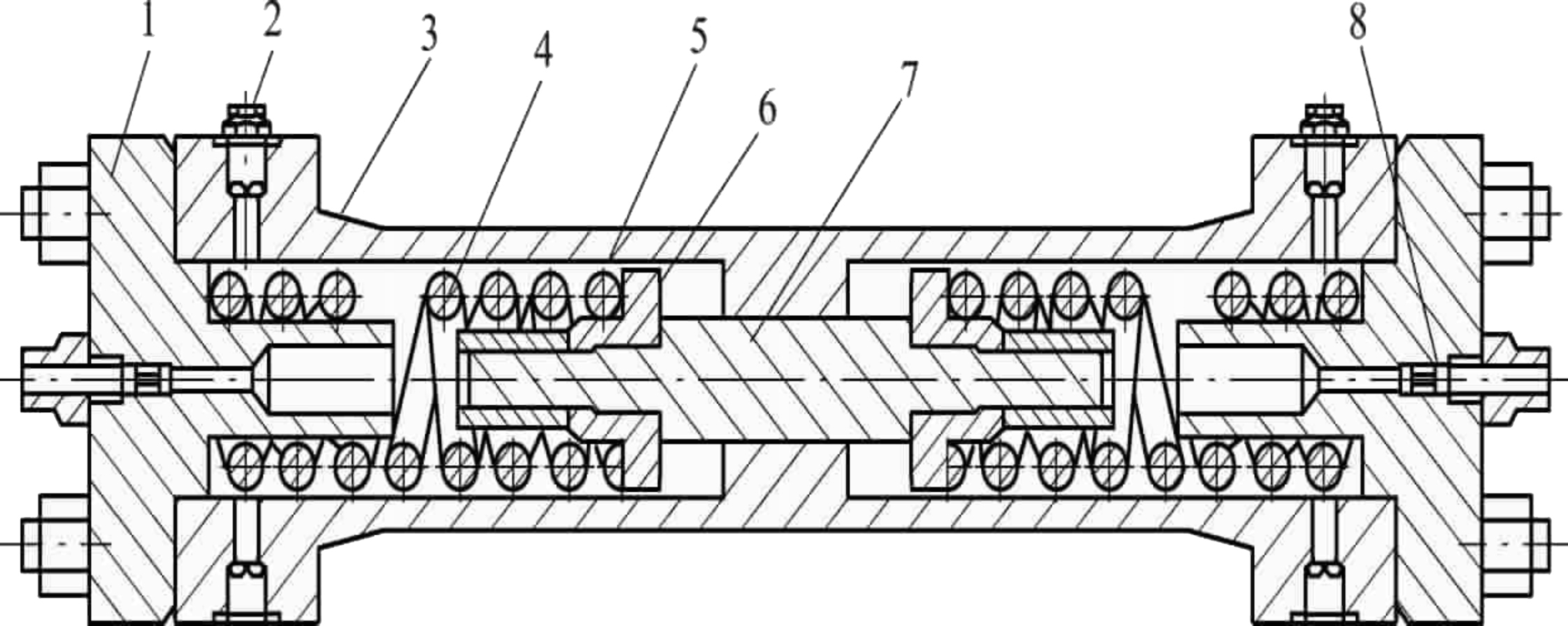

When the pressure difference is small, the flow through the dynamic pressure damper is smaller, and equilibrium of pressure difference is realized by the spring. Thus the dynamic pressure damper has the characteristics of high frequency conduction and low frequency cut-off. It satisfies the dynamic damping ratio of the system and ensures that the system has steady-state accuracy and static stiffness. In addition, this kind of dynamic pressure damper has the characteristics of complete functions, compact structure, convenient maintenance and modification. Therefore, from the point of view of reliability and other performance aspects of a control system and development of technology, it is appropriate to choose a dynamic pressure damper to increase dynamic damping of the control system.
14.3.2. Influence of structural parameters
Changing the aperture of the throttling damper has an obvious influence on the amplitude frequency characteristic and phase frequency characteristic of a dynamic pressure damper. The smaller the aperture is, the lower the cut-off frequency is, but the damping coefficient is relatively small. The
influence of spring stiffness on amplitude frequency characteristics and phase frequency of a dynamic pressure damper is not obvious. The greater the spring stiffness is, the lower the cut-off frequency is. The influence of an isolated plunger area on amplitude frequency characteristics and phase frequency characteristics of a dynamic pressure damper is more obvious than that of spring stiffness. The larger the isolation plunger area is, the lower the frequency cut-off frequency is. The area of isolated plunger is related to the peak value of pressure absorption system of a dynamic pressure damper. In the case of a determination area of an isolated plunger, increasing deformation of the spring can increase the capacity of the dynamic pressure damper to absorb the peak value of pressure.
14.4. Marine hydraulic system screw joint technology
In a hydraulic system, oil leakage of a threaded pipe joint in a hydraulic system is high: 30–40% of oil leakage of the system. The oil leakage of the pipe joint is mainly related to machining accuracy, fastening strength and burr removal of the joint. Leakage caused by pipe joints is mainly caused by: the type of pipe joint not being consistent with the conditions of use; design of the pipe joint being unreasonable; the joint being of poor quality and unable to be sealed; the pipe joint having poor thread precision and being easy to loosen; poor joint assembly; mechanical vibration or pressure pulsation; the bolt creep not being tightened properly in time; or the tightening force of the joint being too large, not enough or uneven.
To prevent leakage failure of a threaded joint, the main considerations in the design of high pressure O-type ring sealing screw joints in a ship’s hydraulic system are as follows: compression of typical threaded joint O-type rings (Table 14.1), guide length of threaded joint (Table 14.2) and sealing surface roughness of joint (Table 14.3). Reasonable selection can be made according to the data and standards shown in the tables.
14.5. Hydraulic system wave absorber
Hydraulic pressure impact, overpressure and noise are common disadvantages of a hydraulic system. They are mostly caused by system unloading, changing direction of liquid flow valve action quickly, throttling, etc. at the moment that the accumulator is full. The essence of hydraulic impact is the fluctuation of hydraulic pressure. In addition to fluid noise, it also induces
structural noise by fluid noise, and finally leads to air noise. These noises seriously affect the performance of a hydraulic system and its components, and lead to damage of the hydraulic pump and its components, and breakage of pipeline seals. Noise reduction measures must therefore be taken to eliminate these noises.
Table 14.1

Table 14.2

Table 14.3

The working principle of a pipe wave absorber is analysed below. The pressure pulsation in a hydraulic system is caused by uneven variation of geometry of a hydraulic pump and system. From the mechanism of noise generated by a hydraulic system, it is impossible fundamentally to eliminate this pressure pulsation; however, a pulsation attenuator can be used to prevent it from spreading to the whole system. Since noise in a hydraulic system has the characteristics of a wide frequency band, an attenuator should theoretically act in the entire frequency range of the fluid noise. Therefore, the structural design of an attenuator is determined by noise characteristics of each hydraulic system to attenuate the main noise frequency of the system.
The pipeline wave absorber is mainly composed of a cylinder, micro-perforated tube, nozzle and so on. A structural diagram is shown in Fig. 14.8. Its purpose and function is to absorb and eliminate hydraulic impact, and reduce noise. As shown in Fig. 14.8, the micro-perforated tube and pressure vessel behind the tube form a sound-absorbing structure, and small holes are arranged in an equilateral triangle. When a certain frequency acoustic wave enters the micro-perforated tube, resonance can be generated. In the vicinity of resonance frequency, due to reciprocating motion of the micro-perforated liquid column under the action of an acoustic wave, acoustic energy is transformed into heat energy due to friction, and a great attenuation is found near the resonance frequency. The size of cavity can
control the peak frequency, so it has the characteristics of a resistance wave absorber and also has the advantages of a resonance wave absorber.
The magnitude of noise reduction is related to the sound absorption coefficient of sound absorption structure, perimeter and area ratio of a channel cross section and length of wave absorber. For this wave absorber, which uses a micro-perforated tube as a lining sound-absorbing material, its noise elimination can be calculated using the Belov formula:
where:
- ΔL 0 is the noise elimination of the wave absorber;
- a 0 is the sound absorption coefficient of vertical absorption material of the lining sound absorption material;
- φ(a 0)is the quantity related to the sound absorption coefficient, normally φ(a 0) = 0.25–0.4;
- P is the girth of the pipe’s cross section;
- S is the cross-sectional area of the pipe; and
- L is the length of the wave absorber.
The perforation rate of a micro-perforated tube and the diameter and length of micro-perforated tube have a direct influence on the absorption effect of a wave. A pipeline wave absorber must be able to absorb the pressure pulsation, prevent duct vibration and reduce air noise effectively. The frequency of a general hydraulic system is less than 1000 Hz. When a muffler test system of a ship is not equipped with a wave absorber, the average peak values of pressure fluctuation before and after the short pipe are 0.092 MPa and 0.091 MPa, respectively; when the test system is equipped with a wave absorber, the average peak-to-peak values of pressure fluctuation before and after the wave absorber are 0.092 MPa and 0.03 MPa, respectively. After a wave absorber is installed in a test system, the sound attenuation is as follows:
In a ship muffler test system, when the system has pressure pulsation, the absorber can absorb pressure fluctuation and reduce the wave peak value. After a wave absorber is installed in the test system, noise reduction is 9.64 dB. The wave absorber can absorb and reduce pressure pulsation of the system, reduce fluid noise and prevent vibration of the hydraulic pipeline. When the hydraulic system uses a pipe wave absorber, the volume of the
cavity and its related parameters should be reasonably matched, so that the natural frequency of the absorber is close to the natural frequency of the hydraulic system. This means that the acoustic wave near the resonance frequency will be greatly attenuated. The effect is better if the wave absorber is installed at the outlet of the hydraulic pump.
14.6. Submarine seawater hydraulic system
A submarine hydraulic system uses seawater as a medium and is a hydraulic system for external hydraulic devices of submarines. It also transfers equipment originally deployed inside submarines to outside the submarine, which saves the limited space and area of a submarine. With seawater as a medium, submarine concealment can be improved effectively. The planet is rich in water resources, and seawater as a working medium is low cost and easy to use. In addition, media leaks and emissions will not cause environmental pollution, making it an environmentally friendly ‘green working medium’.
14.6.1. Superiority of seawater medium
Compared with petroleum-based hydraulic transmission, a seawater hydraulic system has the following advantages:
- 1. Good environmental protection. The leakage of mineral oil can easily cause environmental pollution. The leakage of seawater will not cause environmental pollution, making it an environmentally friendly medium, as noted above.
- 2. High safety. Sea water is non-flammable; it can work in high temperature environments, and can also be used to extinguish fire. It can eliminate fire danger and has no influence on human health.
- 3. Good economy. Seawater is rich in resources. Using seawater as a working medium saves energy and saves a series of costs and troubles in purchasing, transportation, storage, waste oil treatment and so on.
- 4. Easy maintenance. Seawater has a self-cleaning function. Maintenance of a seawater hydraulic system is convenient, and the cost of this maintenance is low.
- 5. System simplification. As a submarine hydraulic system, the ocean is effectively a huge water tank. A seawater hydraulic system thus needs no water tank, cooling device, etc., and the system is greatly simplified, reducing mass and improving efficiency.
- 6. Stable performance. The performance of a seawater hydraulic system is relatively stable.
14.6.2. Key basic technology of seawater hydraulic systems
The physicochemical properties of seawater are different from mineral oil; seawater has low viscosity, poor lubrication, high conductivity and high vaporization pressure. Development of hydraulic equipment and hydraulic components compatible with seawater must therefore address the following key problems.
- 1. Corrosion. Seawater has strong corrosion, the surface of material is brittle and weak, and strong wear will peel off the damaged surface tissue and accelerate the surface wear. Water hardness, pH values and microorganisms in seawater can also adversely affect the system and its components. Materials must have good corrosion resistance, and galvanic corrosion of materials must also be avoided when combined.
- 2. Wear. Water is a kind of weak lubricant. The thickness of lubricating film produced by pure water is only 1/20–1/3 that of mineral oil. It is difficult to form liquid lubrication in friction pairs, which often causes friction. The working environment of a seawater hydraulic system is thus very poor, and the material is easily damaged by many kinds of wear and tear.
- 3. Cavitation. The saturated vapour pressure of water is higher than that of oil. In theory, a seawater hydraulic system is thus more prone to cavitation. Cavitation will destroy solid surface and seals where the flow passes, changing system flows and resulting in pressure fluctuations, vibration and noise, consequently causing many adverse effects. It is necessary to study the cavitation mechanism of a seawater hydraulic system, and to consider new structures and special materials to reduce the occurrence and harm of cavitation.
- 4. Insulation. Seawater is a kind of strong electrolyte, which is conductive. It puts forward higher insulation requirements for electrical control part of system, and the precise electrical control elements of other systems should prevent electromagnetic interference.
- 5. Sealing. The viscosity of water is only 1/50–1/40 that of mineral oil. Under same pressure, the amount of water leaking through the same sealing gap is more than 30 times that of a mineral oil medium. Leakage will affect the safety and performance of system, reduce productivity and directly affect the performance of hydraulic components. Internal leakage can be solved by controlling the clearance between components, and external leakage can be eliminated by using special O-type rings and mechanical seals.
14.6.3. Status of seawater hydraulic systems
Overseas seawater hydraulic technology has entered the stage of application. At present, the working pressure of water hydraulic components overseas can reach 14 MPa, and the flow rate is 14–15 L/min. The United States Navy began studying seawater hydraulic transmission technology at the end of the 1960s. In 1984, seawater operation tools with pressure 14 MPa and flow 30–45 L/min were developed. The British company Fenner in 1988 developed a pressure 14 MPa seawater plunger pump and pressure 10 MPa seawater piston motor, used in 400 m deep underwater operation tools and underwater robots. In Japan’s MITSUBISHI heavy industries, Ebara developed a water hydraulic servo valve with pressure 21 MPa, flow 100 L/min and frequency 47 Hz. In Denmark, Danfoss developed a series of pure water hydraulic components, with a pressure of 14 MPa. Huazhong University of Science and Technology, Southwest Jiaotong University and so on have been studying water hydraulic technology. At present, there is no example of seawater hydraulic system applied to submarines. The challenge of submarine hydraulic systems comes mainly from its performance. In 1998, the 719 Research Institute of China Shipbuilding Industry Corporation completed its research on seawater hydraulic systems. The following problems need to be solved in the application of seawater hydraulic systems:
- 1. Icing. Submarine seawater hydraulic systems work in the ocean. If the temperature of seawater medium falls below 0 °C, non-toxic and pollution-free antifreeze must be added. At present, propylene glycol is used as antifreeze.
- 2. Material. Seawater hydraulic element materials should have the characteristics of corrosion resistance, wear resistance and high mechanical strength. The present method involves spraying a ceramic wear-resistant coating on the contact surfaces of hydraulic components (such as pumps and valves). Common spraying methods include plasma spraying, laser coating, centrifugal thermit process and reactive cladding moulding technology.
- 3. Design methods and experimental means. Because physical and chemical properties of seawater are different from those of hydraulic oil, a new model must be established according to the characteristics of seawater. New design theories and methods are chosen, and simulation tests are carried out according to submarine users’ working conditions.
- 4. Adapt to different depth of work needs. In combination with the submarine diving process, it is necessary to solve balance technology and adaptability of deep seawater back pressure.
- 5. System maintenance. Hydraulic systems with seawater as a working medium need regular monitoring. The accumulation of a system’s impurities and the growth and propagation of various bacteria will block the filter and make seawater smell bad. The change of pH value and hardness of seawater medium will affect the normal operation of a system.
At present, with the development of materials science and precision machining technology, kinds of new engineering materials (such as engineering ceramics, polymer materials and corrosion resistant alloy) and new structure of hydraulic components have appeared, and hydraulic transmission has entered into application and research fields of modern hydraulic transmission.
..................Content has been hidden....................
You can't read the all page of ebook, please click here login for view all page.