13.4. Asymmetrical nozzle flapper type single-stage electrohydraulic servo valve
In the manufacture and use of the nozzle flapper electrohydraulic servo valve, there is often a serious asymmetry. For example, the size of two
nozzles is different, and the gap of the nozzle baffle is difficult to arrange symmetrically when assembly is conducted, and environmental temperature changes result in asymmetry of the geometric structure, etc. In the use of the electrohydraulic servo valve, there is often a need to withstand assessment of extreme work environment of extreme temperature, vibration, impact and acceleration. These easily lead to structural and performance asymmetry. The question of how to obtain the relationship between nozzle flapper valve structure and performance is critical. At present, research on the electrohydraulic servo valve with asymmetric nozzle baffle is still limited. Therefore, this section analyses the asymmetric structure of the nozzle flapper valve, including the asymmetric nozzle and asymmetric damping throttle device, obtains the basic characteristics of the asymmetric nozzle flapper electrohydraulic servo valve, and provides a theoretical basis for development of a new type of electrohydraulic servo valve.
A new type of asymmetric nozzle flapper electrohydraulic servo valve is proposed. A pair of damping throttling devices is installed at two nozzle chambers to compensate for the dynamic characteristics of the electrohydraulic servo valve. This section mainly analyses the structure and characteristics of the valve, including the nozzle chamber and load pressure characteristics, zero pressure characteristics, torque motor driving force and stiffness design method.
13.4.1. Structure of the nozzle flapper type electrohydraulic servo valve
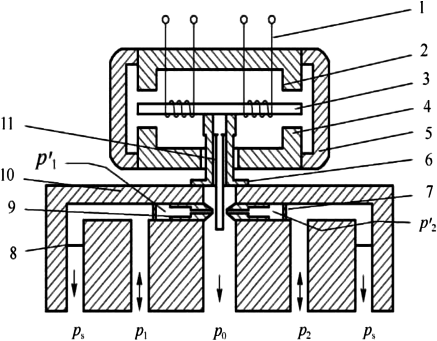
Fig. 13.14 shows a schematic diagram of the nozzle flapper electrohydraulic servo valve with damping throttle. This new nozzle flapper type electrohydraulic servo valve is provided with a pair of damping throttling devices 7 at the nozzle chamber. The electrohydraulic servo valve is composed of two parts: moving iron type torque motor and nozzle flapper valve. When the control current is input, armature assembly 3 of the torque motor generates magnetic field and acts on the electromagnetic field of upper magnet 2 and lower magnet 4, and the armature assembly 3 is deflected. Baffle plate 11 rigidly connected with the armature assembly is deflected relative to the neutral position, resulting in changes in pressure in two nozzle chambers, resulting in pressure difference (p
1 – p
2), thereby actuating the actuator. When the size and direction of control current change, size and direction of output flow of the electrohydraulic servo valve or pressure load magnitude can be changed, this changes the execution speed and direction of movement mechanism or output force. In Fig. 13.14, p
s is oil supply pressure, p
1, p
2 are
two load chamber pressures that are connected to the actuator, p
0 is oil return pressure, and
 and
and
 are the pressures of the two nozzle chambers.
13.4.2. Theoretical analysis
I. Pressure-flow equation of the nozzle flapper electrohydraulic servo valve
1. Static pressure characteristics of the nozzle flapper valve
Fig. 13.15 shows the sketch map of dual nozzle flapper electrohydraulic servo valve with damping throttle. Assuming that the volume of two nozzles is small, the compressibility of liquid in chamber can be disregarded. The nozzle flapper type electrohydraulic servo valve is equipped with two fixed orifices A
b1 and A
b2 at two chambers of the nozzle. They are used to regulate the linearity of load chamber pressure and its dynamic characteristics.
Considering the continuity of flow that provides the oil, the following can be obtained:
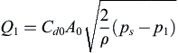
The flow equation of orifice A
0 and A
b1 and the flow equation at the nozzle are:
 (13.61)

 (13.62)
 (13.63)
where:
 (13.64)
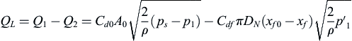
Ignoring the compressibility of oil in nozzle chamber, there is Q2=
 , and from Eqs. (13.62) and (13.63), the load control pressure is:
 (13.65)
When the load is fixed, i.e. Q
L =0, the static pressure of oil in nozzle can be obtained from Eqs. (13.64) and (13.65):
 (13.66)
Similarly, there are:
 (13.67)
 (13.68)
According to the design criteria of the nozzle flapper valve, generally there is:
kb1= CdfπdNxf0/Cdb1Ab and kb2= CdfπdNxf0/Cdb2Ab2 are liquid resistance ratio at nozzle 1 and nozzle 2, respectively. The pressure characteristics of two nozzle chambers at different liquid resistance ratio are obtained from Eqs. (13.66) and (13.68), as shown in Fig. 13.16.
In Fig. 13.16, curves 1 and 2 are pressure characteristic curves of the two nozzle chambers of ordinary nozzle flapper type electrohydraulic servo valve with no damping throttle, and at zero position, there is
 10/ps=
20/ps=0.5. Curves 3–8 are pressure characteristic curves of the nozzle flapper type electrohydraulic servo valve with damping throttle at different liquid
resistance ratio: at the zero position, there is
10/ps=
20/ps<0.5; the larger the liquid resistivity ratio is, the more the curve moves downward, the greater the range of pressure regulation is; when the two damping orifices are asymmetric, that is Ab1≠Ab2, the pressure characteristics of the nozzle chamber in curves 3 and 6 are asymmetric, and there is
10/ps≠
20/ps at the zero position.
10/ps=
20/ps=0.5. Curves 3–8 are pressure characteristic curves of the nozzle flapper type electrohydraulic servo valve with damping throttle at different liquid
resistance ratio: at the zero position, there is
10/ps=
20/ps<0.5; the larger the liquid resistivity ratio is, the more the curve moves downward, the greater the range of pressure regulation is; when the two damping orifices are asymmetric, that is Ab1≠Ab2, the pressure characteristics of the nozzle chamber in curves 3 and 6 are asymmetric, and there is
10/ps≠
20/ps at the zero position.

The pressure characteristics of two load chambers at different liquid resistance ratios are obtained by Eqs. (13.65) and (13.67), as shown in Fig. 13.17. In this figure, curves 1 and 2 are pressure characteristic curves of the two load chambers of an ordinary nozzle flapper type electrohydraulic servo valve with no damping throttle, and at the zero position, there is p10/ps=p20/ps=0.5. Curves 3–8 are the load pressure characteristic curves of the nozzle flapper type electrohydraulic servo valve with damping throttle at different liquid resistance ratios: at the zero position, there is p10/ps=p20/ps>0.5; the larger the liquid resistivity ratio is, the more the curve moves upward, the smaller the range of pressure regulation is; when the two damping orifices are asymmetric, that is Ab1≠Ab2, the pressure characteristics of the load chamber in curves 4 and 5 are asymmetric, and there is p10/ps≠p20/ps at the zero position. This kind of asymmetrical nozzle flapper type electrohydraulic servo valve can be used for load matching control of hydraulic pressure control systems and asymmetrical hydraulic cylinders.
From Figs. 13.16 and 13.17, it can be seen that the double nozzle flapper electrohydraulic servo valve with damping throttle has a small range of load pressure changing, the pressure changing range of the nozzle chamber is large, the control range of the electric signal is increased, and the control precision and energy utilization efficiency of the nozzle flapper valve are improved. When the double nozzle flapper electrohydraulic servo
valve without damping throttle is blocked at the nozzle, the double nozzle flapper type electrohydraulic servo valve with asymmetric damping throttle can be taken as a reference. The pressure characteristics and load pressure characteristics of the nozzle chamber are analysed under symmetric blockage Ab1=Ab2 and asymmetric blockage Ab1≠Ab2.

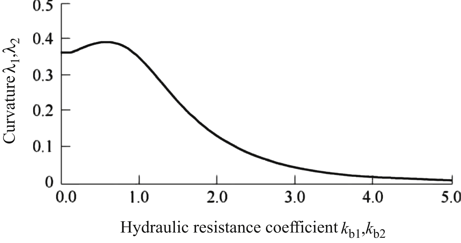
The hydraulic servo system usually works near the zero position of the nozzle flapper valve, and the pressure change process at the load port is often required to ensure smooth operation. In order to obtain the linearity of load pressure at the zero position of the nozzle flapper valve, the concept of curvature in mathematics is introduced. Curvature describes the degree of curvature of a curve, the rotation rate of tangent angle of a point on a curve to the length of an arc, indicating the extent to which the curve deviates from the tangent. To make the load pressure curve change gently, the smaller the curvature, the better. The curvature expression is:
 (13.70)
where:
From Eqs. (13.65)–(13.68), the curvature of load pressure curves p1/pS and p2/pS at zero position (xf/xf0=0) are, respectively:
 (13.71)
 (13.72)
The relationship between the curvature of load pressure curve and liquid resistance coefficient at the zero position is obtained by Eqs. (13.71) and (13.72), as shown in Fig. 13.18. When the liquid resistance coefficient
is 0.6, curvature reaches the peak value is 0.39. In order to increase the linearity of load pressure curve at the zero position, the area near the peak of curvature should be avoided when selecting the working point. Considering the actual pressure control range, it is suggested that the liquid resistance coefficient range is between 1.5 and 2.5, and the curvature value is moderate.
2. Pressure characteristic at zero position
Assuming x
f = 0, from Eqs. (13.65)–(13.69), when the nozzle flapper type electrohydraulic servo valve is in the zero position, pressure equations of each volume chamber are as follows:
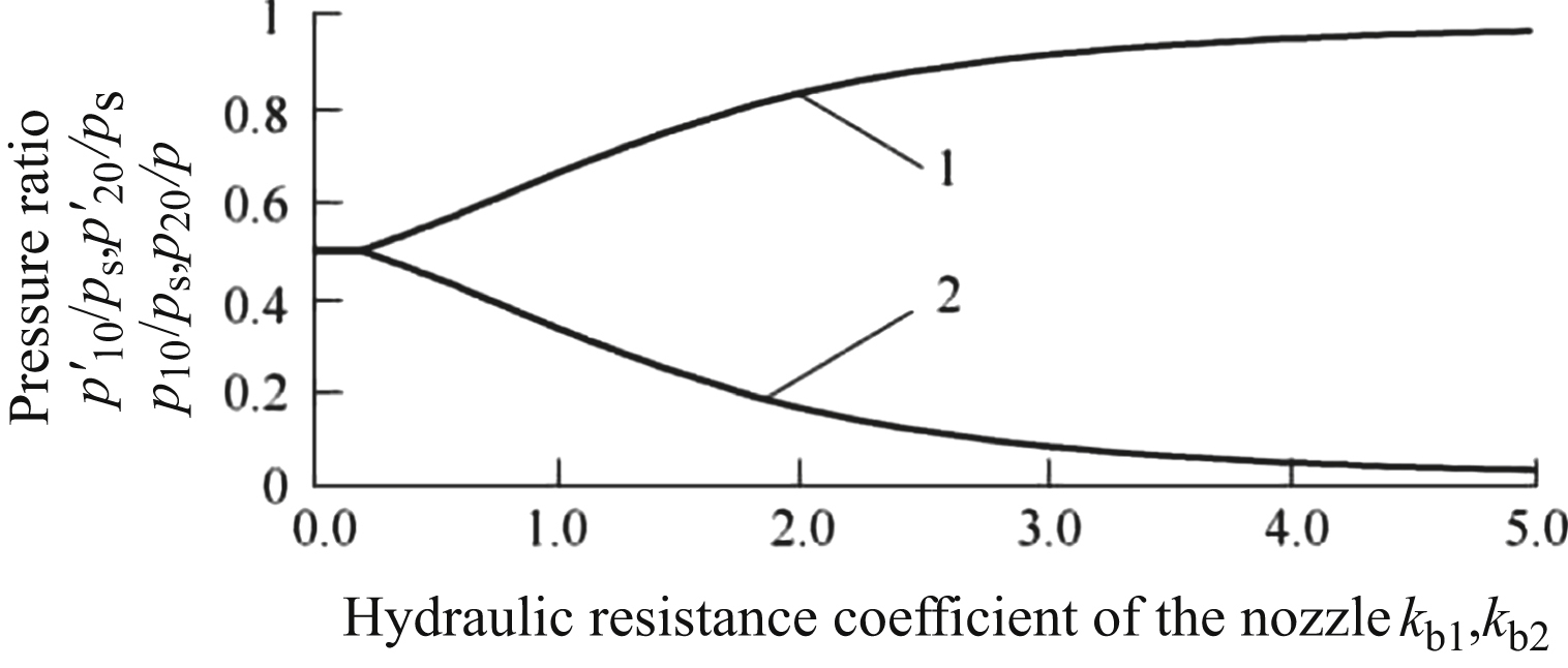
Fig. 13.19 show the pressure characteristics at the zero position of the nozzle chamber and load chamber. It can be seen that the zero position pressure varies with change of the nozzle liquid resistance coefficient, and when the liquid resistance coefficient is zero, load pressure is 50% of oil supply pressure, that is,
10/ps=p10/ps=0.5 and
20/ps=p20/ps=0.5. The larger the liquid resistance coefficient is, the lower the zero position pressure of the nozzle chamber is, and the higher the zero position pressure of load chamber is, and
10/ps=
20/ps<0.5 and p10/ps=p20/ps>0.5.
II. Driving force of the flapper
The torque motor needs to provide enough force to meet the needs of the driving flapper, so a calculation method of driving force of the baffle is analysed. By using the Bernoulli equation, the force acting on the baffle at nozzle 1 is obtained:
where v1 is the velocity at which fluid exits the nozzle hole.
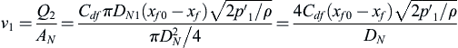 (13.78)
where AN is the nozzle hole area.
Similarly, we have:
where Kps is the steady pressure coefficient.
When the nozzle flapper valve is in the neutral position,
 =0, we have:
It can be seen from Eq. (13.83) that the steady pressure coefficient of the nozzle flapper valve K
ps<1.
Generally, the nozzle flapper valve design requires (xf0/DN)<1/16. At this point, the second term is much less than the first term in Eq. (13.81). Because of x
f< x
f0, the third item is much smaller than the second item. Eq. (13.81) can be simplified as follows:
The stiffness of the nozzle flapper valve is approximately:
13.4.3. Application analysis
- 1. In the first stage of the two-stage electrohydraulic servo valve of a certain type of aircraft adopts structure of the nozzle flapper valve, the pressure of the nozzle chamber is usually detected during the product test. After the assembly test, it is found that the zero position pressure is less than 50% of oil supply pressure. After decomposition, it is found that the fixed throttle has burrs at entrance, requiring deburring and reassembly. After testing, zero position pressure is restored to 50% of oil supply pressure. When the inlet of throttle has burr, it is equivalent to increasing the liquid resistance coefficient, such as curves 3 and 8 in Fig. 13.16; after deburring, it is equivalent to curves 1 and 2 in Fig. 13.16. The measured result is consistent with curve 2 shown in Figs. 13.16 and 13.19.
- 2. When the nozzle flapper electrohydraulic servo valve is tested, the pressure of the two load chambers is different at the zero position, and is greater than 50% of oil supply pressure. After decomposition, it is found that the nozzle shape is not good and there is a significant burr, and two nozzles do not have the same degree of clogging. When the nozzle is asymmetrically blocked, the pressure of the two load chambers is different and is greater than 50% of oil supply pressure, consistent with the values of curves 4 and 5 in Fig. 13.17 at the zero position. It returns to normal after being replaced by symmetrical shape and no burr left and right nozzle and throttle orifice. Experimental phenomena are consistent with theoretical analysis.
- 3. The electrohydraulic servo valve and servo mechanism of a product have been shaking; high temperature and low temperature test indicate no problem; after normal temperature is restored, a pressure characteristic curve appears to be a zigzag shape. Analysis shows that the assembly stress of the two nozzles and fixed restrictor is inconsistent, due to asymmetry of the coordination dimension change caused by thermal expansion and cold contraction at high and low temperature cycles. In particular, asymmetry of the flow coefficient of the nozzle flapper valve increases, resulting in transient asymmetric load pressure intensifying, causing pressure fluctuation. Test results show that when assembly stress is considered and the assembly process is improved, after adding a hydraulic temperature matching test, the electrohydraulic servo valve eliminates fluctuation of pressure.
..................Content has been hidden....................
You can't read the all page of ebook, please click here login for view all page.