
13.5. Asymmetry of the nozzle flapper valve of the two-stage electrohydraulic servo valve with force feedback
In manufacture and assembly of the electrohydraulic servo valve, theoretically symmetrical micro-structure of the nozzle flapper valve often exhibits asymmetrical characteristics, such as asymmetrical nozzle baffle clearance and asymmetrical nozzle diameter. Small asymmetry of structure may have a great influence on the characteristics of the electrohydraulic servo valve, and some asymmetric structures may also improve the performance of the electrohydraulic servo valve. So far, there is little research on the asymmetric structure of the nozzle baffle valve of the electrohydraulic servo valve and its influence on valve characteristics. For this reason, asymmetric structure is divided into two forms: asymmetrical nozzle baffle clearance and asymmetrical nozzle diameter. The pressure characteristics of the nozzle baffle valve chamber and response characteristics of the electrohydraulic servo valve are discussed here.
13.5.1. Symmetry and asymmetry characteristics of initial clearance of the nozzle baffle
I. Fundamental equations
1. Pressure flow balance equation of the nozzle flapper valve
Fig. 13.20 shows a schematic diagram of the double nozzle flapper valve when initial clearance of the nozzle baffle is varied. As shown in the figure, when the baffle is in the zero position, the distance between the upper and lower nozzles and the baffle is called the initial clearance of the nozzle baffle. When the distance between the two nozzles and the baffle plate is equal, this is called symmetrical initial clearance of the nozzle baffle. When the distance between the two nozzles and the baffle plate is unequal, this is called asymmetrical initial clearance of the nozzle baffle.
The design of the nozzle flapper valves generally follows these guidelines:
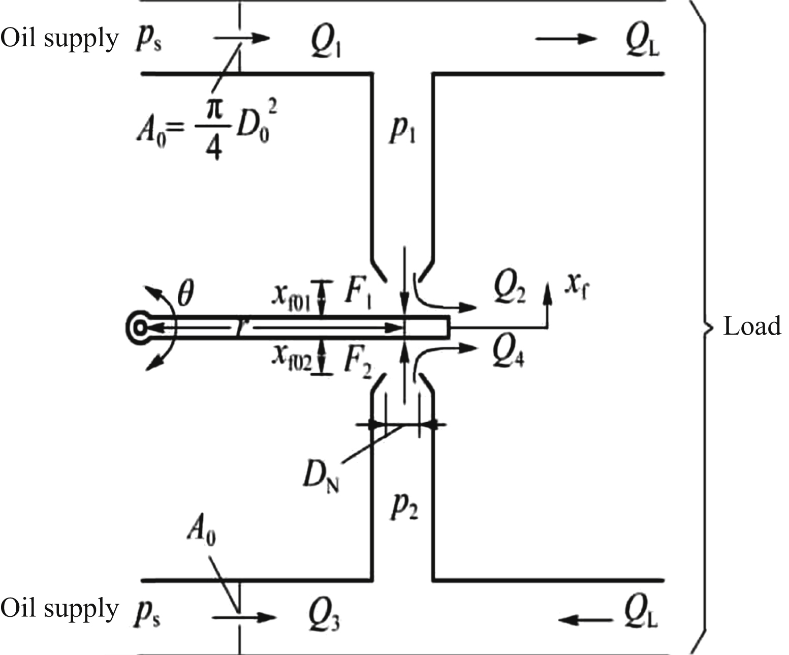
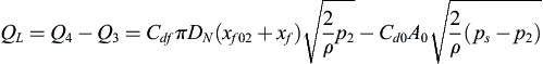
According to Fig. 13.20, flow continuity of fluid can be obtained as follows:
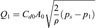
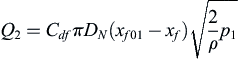
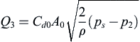
The following can be obtained from the orifice flow equation:
 (13.90)
 (13.91)
 (13.92)
Similarly, the following can be obtained by the orifice flow equation:
 (13.93)
 (13.94)
Similarly, we have:
 (13.95)
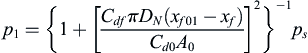
From Eq. (13.92), steady pressure expression at both ends of the valve core are expressed as follows:
 (13.96)
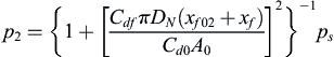 (13.97)
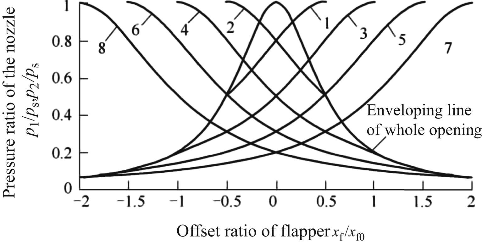
From Eqs. (13.96) and (13.97), the curve family of ratio of the nozzle pressure to supply pressure varies with relative displacement of the baffle being obtained, as shown in Fig. 13.21.
At the same time, the zero position pressure at both ends of the main spool can be obtained as follows:
 (13.98)
 (13.99)
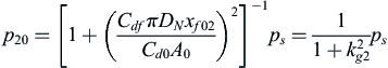
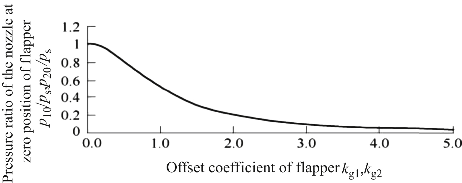
From Eqs. (13.98) and (13.99), the curve family of ratio of the nozzle pressure to supply pressure varies with baffle offset coefficient is obtained, as shown in Fig. 13.22.
After Eq. (13.92) is zero position linearized, it is in the form of:
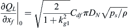
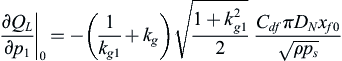
Finding the partial derivative of Eq. (13.92) at the zero position and using Eq. (13.98), the following can be obtained:
 (13.101)
 (13.102)
 (13.103)
Similarly, expression of Eq. (13.103) after linearization is:
 (13.104)
2. Hydrodynamic calculation of the nozzle flow acting on the baffle
As shown in Fig. 13.20, the Bernoulli equation can be used to calculate the hydrodynamic force of jet acting on the baffle. We have:
 (13.106)
Substituting Eq. (13.106) into Eq. (13.105), we have:
The equation of F
2 can be deduced by a similar method:
II. Characteristics of initial clearance symmetry or asymmetrical nozzle flapper valve
According to analysis results of the electrohydraulic servo valve nozzle flapper valve with asymmetrical initial clearance of the nozzle flapper, considering the flow balance equation of the main spool movement, torque motor moment equilibrium equation and force equilibrium equation of the main valve spool, simulation model of the electrohydraulic servo valve can be established by using MATLAB/SIMULINK. By changing two clearance of the nozzle baffle x
f01, x
f02, the response curves of the main spool displacement and deflection angle of the baffle plate, and pressure variation curve of the chamber under different conditions are obtained. The following conclusions can be drawn:
- 1. The change of initial clearance of a single nozzle baffle has little influence on the response characteristics of the electrohydraulic servo valve. According to simulation results, the smaller the initial clearance of the nozzle baffle, the faster the response of the electrohydraulic servo valve.
- 2. The simultaneous change of initial clearance of double nozzle baffle has a significant influence on the response characteristic of the electrohydraulic servo valve.
- 3. The difference of the change of initial clearance of the double nozzle baffle will cause zero offset of the electrohydraulic servo valve.
13.5.2. Symmetry and asymmetry of the nozzle diameter
I. Fundamental equations
1. Pressure flow balance equation of the nozzle flapper valve
Fig. 13.23 shows a schematic diagram of the double nozzle flapper valve when the nozzle diameter is varied. When the two nozzle diameters are equal, it is called symmetrical nozzle diameter; when the two nozzle diameters are unequal, it is called asymmetrical nozzle diameter.
where k
d1,
k
d2
is the nozzle diameter change coefficient.
According to Fig. 13.23, the flow continuity of fluid can be obtained as follows:
The following can be obtained from the orifice flow equation:
(13.113)
 (13.114)
(13.115)
(13.114)
(13.115)
Similarly, the following can be obtained by the orifice flow equation:
(13.116)
 (13.117)
Similarly, we have:
(13.118)
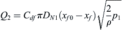
Similarly, the relations between P
1, P
2 and P
s at steady state are as follows:
 (13.119)
 (13.120)
From Eqs. (13.119) and (13.120), the curve family of ratio of the nozzle pressure to supply pressure varies with relative displacement of the baffle is obtained, as shown in Fig. 13.24.
At this point, when the baffle is in the median position, the zero position pressures expressions are:
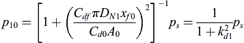 (13.121)
 (13.122)
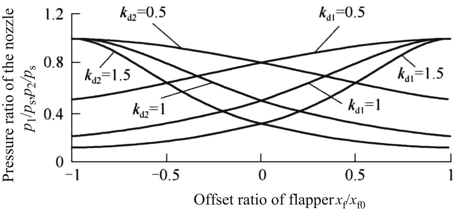
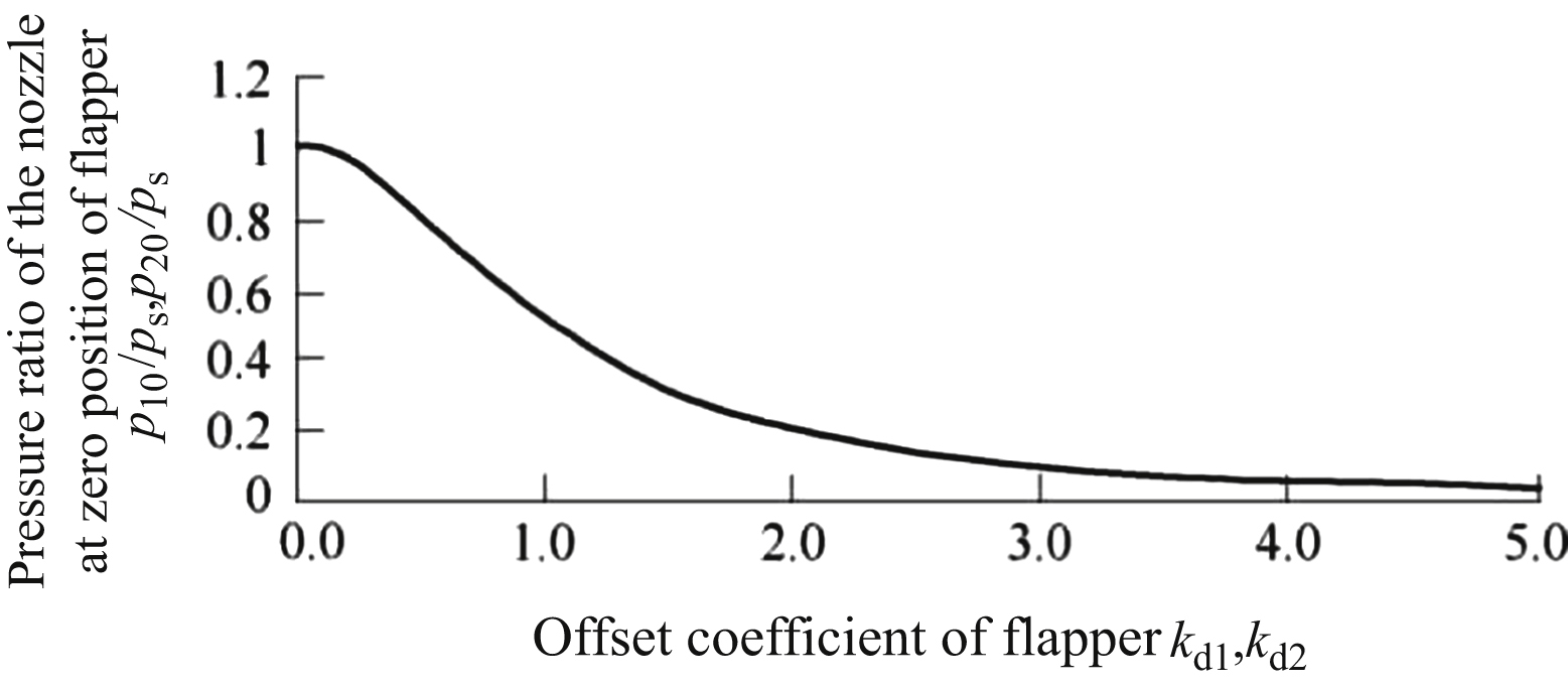
From Eqs. (13.121) and (13.122), the curves of ratio of the nozzle pressure to supply pressure varies with baffle offset coefficient are obtained, as shown in Fig. 13.25.
Expression of the flow pressure equation after linearization is:
 (13.123)
 (13.124)
2. Hydrodynamic calculation of the nozzle flow acting on the baffle
As shown in Fig. 13.24, the Bernoulli equation can be used to calculate hydrodynamic force of jet acting on the baffle. We have:
 (13.126)
Substituting Eq. (13.126) into Eq. (13.125), we have:
The equation of F
2 can be deduced by a similar method:
II. Influence of symmetry nozzle diameter and asymmetrical nozzle diameter
A simulation model of an electrohydraulic servo valve with asymmetrical nozzle diameter can be established by using MATLAB/SIMULINK. By changing the two nozzle diameters, the response curves of the main spool displacement and deflection angle of the baffle plate, and pressure variation curve of the chamber under different conditions are obtained. The influence of symmetry nozzle diameter and asymmetrical nozzle diameter is manifested mainly in the following aspects:
- 1. The change of initial clearance of a single nozzle baffle has little influence on the response characteristics of the electrohydraulic servo valve. According to simulation results, the smaller the nozzle diameter, the faster the response of the electrohydraulic servo valve.
- 2. The simultaneous change of double nozzle diameter has a significant influence on the response characteristic of the electrohydraulic servo valve.
- 3. The difference of change of double nozzle diameter will cause zero offset of the electrohydraulic servo valve.
..................Content has been hidden....................
You can't read the all page of ebook, please click here login for view all page.