
Chapter 8
Single Stage Overflow Valve in Aerocraft Hydraulic Control Systems
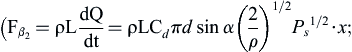
This chapter combines the development process of an electrohydraulic energy system for missile control modules and overflow valves and relief valves for launch vehicles. It also introduces the single stage overflow valve in aircraft hydraulic control systems, that is, a single stage overflow valve with balanced piston and fixed orifice, including the principle of integrated type overflow valves used in aircraft, three-in-one comprehensive function of vibration reduction, noise elimination and voltage stabilizing of new type overflow valves with balanced piston and fixed orifice, dynamic characteristics of the new overflow valve. Through computer simulation, the method of determining geometric parameters under the optimum dynamic working conditions is obtained, and some experimental results of some products are provided.
After aircraft hydraulic components are manufactured, assembled and debugged, they are installed directly on the hydraulic steering engine. When the aircraft receives a command and suddenly takes off and works, in the process of starting the hydraulic pump with the primary energy, the overflow valve is in the state of setting pressure – that is, the hydraulic pump belongs to the starting process with load. This kind of aircraft has a high demand for the dynamic response characteristics of an airborne overflow valve and its working pressure, and the system pressure setting time is usually within a few tens of milliseconds. For this reason, the static and dynamic characteristics of an integrated overflow valve with balanced piston are analysed. A mathematical model is established. The theoretical characteristics and experimental results show that this integrated overflow valve has three special functions: vibration reduction, noise elimination and voltage regulation.
8.1. Characteristics and working principle of single stage overflow valve with balanced piston and fixed orifice
8.1.1. Structure characteristics
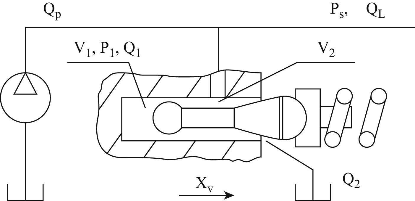
As shown in Fig. 8.1, the single stage overflow valve with balanced piston and fixed orifice is composed of a valve core, valve seat, spring and other components. The valve core adopts a gourd-shaped special new structure form, and the valve core and valve seat form a pressure control chamber, a pressure sensing chamber and a fixed orifice.
- 1. The small ball head of the valve core and the valve seat hole form a dynamic damping hole to form a fixed throttling device; the valve seat has a geometric cavity, and the dynamic pressure sensation and feedback can be realized.
- 2. The valve core adopts balanced piston and shockproof tail end structure, and plays a guiding role at the same time in working state. The upper surface of the ball head conical valve core is spherical. The valve core and spring seat are located by spherical contact positioning, and the valve core and spring axial force transfer find the centre by themselves.
- 3. Curved profile spool structure improves the angle and momentum of the liquid outflow flow, and compensates for the hydraulic force.
8.1.2. Working principle
The working principle diagram of the single stage overflow valve with balanced piston and fixed orifice is shown in Fig. 8.2. The single stage overflow valve with balanced piston and fixed orifice is used for system pressure build-up and stability control, maintaining the system’s operating pressure.


- 1. When the hydraulic pump starts running, the valve core is normally in the closed state. It shuts off the passage between the pressure oil and the return line to stop the flow of the hydraulic pump pressure oil and establish the system pressure through the imaginary filling of the oil inlet chamber.
- 2. When the system oil circuit is full of oil, the oil pressure rises gradually. Oil from the fixed throttling device goes into the pressure control chamber and the pressure chamber. The pressure perceived by the piston area A of the pressure sensing chamber is compared with that of the pre-set spring force to form a simple load feedback loop, thereby pushing the valve and compressing the spring. When the oil flow rate is too large, the oil pressure rises. The valve core opens and connects the high pressure circuit to the return circuit. The pressure oil is discharged into the oil tank to limit the increase of the system oil pressure, so as to realize the stable pressure control and ensure the normal working pressure of the system. The greater the stiffness of the spring, the greater the amount of pressure change corresponding to a certain amount of opening. The less stiffness the spring has, the smaller the amount of pressure corresponding to the opening; the smoother the pressure, the better the pressure-flow characteristics.
- 3. The function of the fixed orifice is to form an oil tank, form a dynamic hydraulic spring, limit the flow of pressure oil in the pressure sensor, slow down the speed of the valve core (whether closed or open), increase dynamic damping, and ensure working stability and dynamic characteristics of valve.
- 4. The single stage overflow valve with balanced piston and fixed orifice serves as a relief valve to limit the maximum oil pressure of a certain oil circuit or system. The valve is normally a closed pressure control valve (also known as a pressure relief valve). The valve core is closed by the spring, and the pressure oil from a certain oil passage or system acts on the valve core. When the pressure is too high, the valve core is opened and the pressure oil is allowed to be discharged into the oil tank.
8.1.3. Performance characteristics
- 1. Vibration reduction. Flow fluctuation from the hydraulic pump or load causes a sudden increase or decrease in control pressure, after throttling by fixed orifice, which is felt by the pressure sensing chamber. After the pressure fluctuation is slowed down, the pressure is compared with the pre-set spring force. The control pressure indirectly controls the opening of the valve, thereby having the function of self-damping and buffering. For the direct acting overflow valve, the valve core directly senses the control pressure, and the control pressure is compared directly with the spring force arranged so there is no vibration reduction function.
- 2. Noise elimination. The liquid flow is carried out on the surface of the geometric space surface composed of the micro valve core and the valve body. After entering the valve, the fluid forms a continuous layer on the surface. The surface structure and the balancing piston can partially eliminate the flow noise produced by throttling.
- 3. Voltage stabilizing. The fixed throttling device and the pressure sensing chamber form a dynamic hydraulic spring, which greatly weakens the pressure variation caused by the flow fluctuation and dynamically controls the pressure stability.
8.2. Working point and basic characteristics
8.2.1. Working point
The steady-state characteristic of the overflow valve means under the steady working condition which inlet pressure of overflow valve has no mutation, the pressure, flow characteristics and range of adjustment are controlled by the valve.
I. Opening pressure
When the overflow valve is in stable overflow, from the force equilibrium equation of valve core, opening pressure is obtained as follows:
where:
II. Steady working pressure
The steady working pressure of the overflow valve is:
From the above equation, the following is obtained:
 (8.2)
(8.2)
where:
III. Steady flow
The steady flow of the overflow valve is:
where:
- 1. When the working pressure of the overflow valve increases, the valve displacement increases and the working flow of the overflow valve also increases accordingly. The less stiff the spring is, the more stable the pressure; the greater the seat area, the greater the spring pre-compression. At the same amount of incremental flow, the smaller the amount of pressure changes, the better the corresponding pressure flow characteristics are.
- 2. Properly designed spring stiffness and valve seat diameter can yield a constant load pressure essentially independent of the load flow.
8.2.2. Basic equations
The dynamic characteristic of an overflow valve is the step response of an overflow valve to the disturbance momentum (such as the rated flow step signal) or the input quantity (such as the rated pressure step signal). Regarding the so-called good dynamic characteristics, which is the overflow valve is in stability, the overshoot of inlet pressure is small and the transition time is short.
The size of the dynamic damping hole and the size of the pressure-sensing cavity of the new overflow valve are formed by the geometrical matching sizes of the valve core and valve seat, which are generally difficult to measure accurately. In order to determine reasonably the structural parameters of these two coordinate sizes, the kinematic differential equation of the new valve is established and transformed into a state equation. The four-order Runge-kutta-Gill method is then used to solve the numerical integration of the nonlinear equation to obtain a numerical solution. The disturbance quantity is a step signal of the rated flow, and different step response curves are obtained when the size of the fixed orifice and the pressure-sensing cavity are changed. Thus, a set of structural parameters with satisfying dynamic characteristics can be determined, which provides a theoretical basis for the design of valve parameters.
I. Kinematics equation of valve core
 (8.6)
(8.6)
where:
-
P1  is the pressure of the pressure-sensing cavity (Pa);
 - m is the equivalent mass of the valve core elastic assembly (kg);
- B is the viscous damping coefficient;
-
Fβ1  is the steady hydrodynamic force (N);
 -
Fβ2  is the transient hydrodynamic force (N);
 -
C
v
is the velocity coefficient,
Cv=0.98  ; and
; and - L is the damping length (m).
II. Flow equation at the main throttle orifice
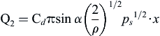 (8.7)
(8.7)
III. Fixed orifice flow equation
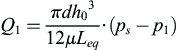
A parabolic gap is formed between the spherical piston of curved valve core and the cylinder surface of valve seat. The equivalent throttling area formed by both surfaces is fixed and therefore becomes a fixed orifice. If the flow in the gap is laminar, the flow through the gap between the ball head and the cylindrical hole is:
where:
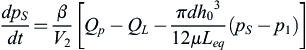
IV. Flow continuity equation of pressure control chamber
where:
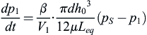
V. Flow continuity equation of pressure sensing chamber
8.2.3. State equation
The kinematic differential equations described by Eqs. (8.4)–(8.10) are nonlinear and difficult to transform into transfer function form and solve by traditional methods. For this reason, they are transformed into first-order state equations and solved numerically. The equations of state can be transformed into the following:
 (8.13)
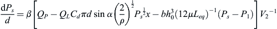 (8.14)
8.2.4. Basic characteristics and analysis
I. Mathematical simulation
The first-order differential equations described in Eqs. (8.11)–(8.15) can be solved using the Runge-kutta-Gill method. We enter the structural parameters and basic fluid parameters of the overflow valve; the initial condition is the pre-pressure kx
0 of the setting spring, the variable parameter is the function size h
0 of the fixed orifice, the pressure-sensing chamber volume V
1 and the step signal is the rated flow Q
p − Q
L of the overflow valve. Under the above conditions, the changing process of dynamic time-varying parameters can be obtained – that is, the overflow valve inlet pressure p
s, valve displacement x
v, pressure-sensing chamber pressure p
1 and other changes with time, including the starting process. The mathematical simulation of a micro overflow valve is carried out. When
h0=5μm
 ,
,
V1=19.2mm3
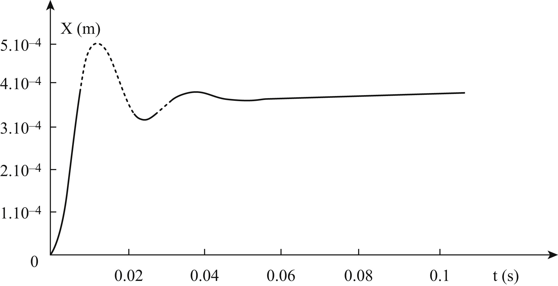
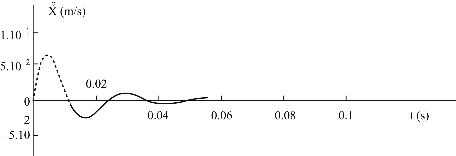
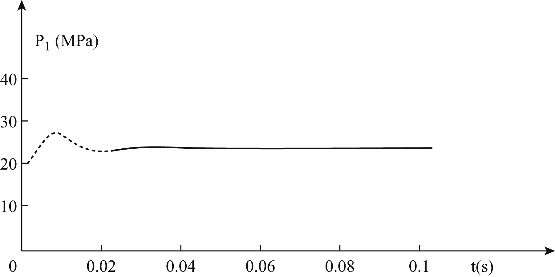
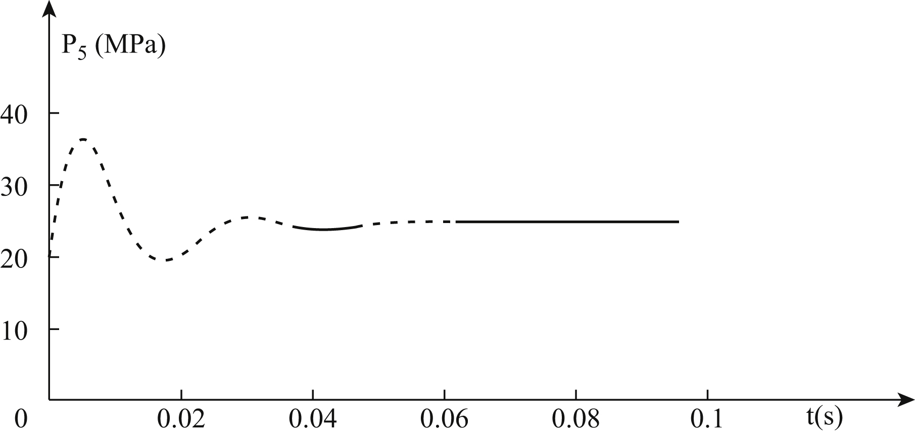
 , and it has satisfactory dynamic characteristics. The dynamic response curves of the overflow valve core displacement, velocity, pressure-sensing chamber pressure and pressure control chamber pressure are shown in Figs. 8.3–8.6.
II. Test results
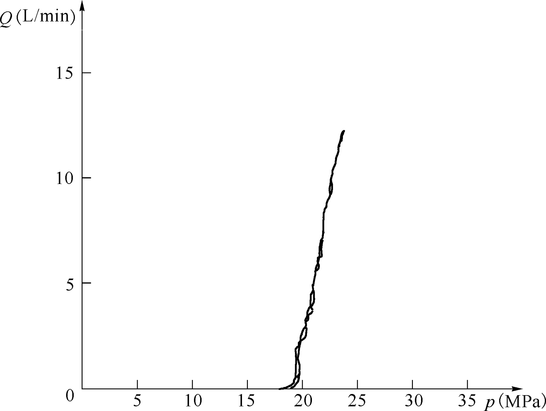
Various contrast tests are performed on the conical valve and the single stage overflow valve with balanced piston and fixed orifice shown in Fig. 8.1. The test results show that in the working state, the conical valve itself and its connections have severe vibration, throttle flow noise harsh, howling over 90dB, and the single stage overflow valve with balanced piston and fixed orifice has almost no vibration and throttle noise. The steady-state characteristic test curves are shown in Figs. 8.7 and 8.8. The conical valve has a large range of pressure fluctuation under certain flow conditions and has poor starting characteristics; the single stage overflow
valve with balanced piston and fixed orifice has stable control pressure and good starting characteristics. The experimental results are in good agreement with the analytical results.

III. Characteristics analysis
- 1. The single stage overflow valve with balanced piston and fixed orifice shown in Fig. 8.1 is compact, novel and ingenious in design. The special-shaped valve core is arranged in the limited space, at the matching of the valve forms the key factors of improving dynamic characteristics, such as fixed orifice, pressure-sensing chamber and pressure control chamber, which can realize the accurate control of the pressure. The valve has a three-in-one comprehensive function of vibration reduction, noise elimination and voltage stabilizing. Accurate pressure control can be achieved and proper design of the spring and valve path allows a constant load pressure that is essentially independent of the load flow.
- 2. In the small flow hydraulic control system, the proper size of the orifice and the volume of the pressure-sensing chamber can be determined by mathematical simulation. The method of determining the relative size and the dynamic characteristics of satisfactory starting is used, and the geometric parameters under the optimum dynamic working condition are determined.
- 3. The single stage overflow valve with balanced piston and fixed orifice is small and lightweight, so it can be integrated conveniently, and can be designed as a miniature screw in type plug-in valve or a superposition valve, which has high reliability and good maintainability. It can also realize the integrated closed system design of aircraft conveniently.
8.3. Influence of structural parameters on dynamic characteristics
8.3.1. Pressure control mechanism
Fig. 8.9 shows a structure sketch map of integrated hydraulic overflow valve with balanced piston. It is composed of a special shape of a valve core, a valve body, a spring, a spring seat, etc. The valve core of the special shape and the valve body form a pressure control cavity, a pressure-sensing chamber and a fixed throttling hole.
The valve core with the balanced piston and the valve body form a fixed throttling hole and a pressure-sensing chamber, and the control pressure is mainly compensated by the pressure sensing chamber. The pressure-sensing chamber composed of the balanced piston and the valve body is designed to facilitate pressure feedback and dynamic pressure sensor tests. The space between the valve body, the valve core and the valve stem forms a pressure control chamber. The shape of the valve core can change the flow direction and hydrodynamic force of liquid and offset partial liquid flow force. Force is transmitted through the spring seat connection of the concave spherical
surface between the valve core and the spring. The direction of the hydrodynamic force can be changed by the spring chamber. The direction of the spring force can also be balanced with the axial hydraulic pressure by fine adjustment of the spherical spring seat.
The overflow valve is mainly used to set the stability work pressure of hydraulic system or normal pressure when there is no pressure shock. When the hydraulic pump starts, the valve core of the overflow valve is not opened, and the line is closed between the high-pressure pipe and oil tank. The overflow valve prevents oil flowing from the pump back into the oil tank, where the initial pressure of oil is set by using the compressibility of the oil. With rotation of the pump, a certain volume of hydraulic oil is output. The pipe is gradually filled with oil, because of the volume of the chamber and the compressibility of hydraulic oil. The sealed oil pressure gradually increases until the fluid pressure is balanced with the spring force. When the work pressure exceeds the pre-set preload of the spring, the valve core is opened, and oil is released through valve core throttling surface and spring cavity, and flows into the fuel tank from the pressure chamber. Therefore, the overflow valve can control the pressure and relieve the pressure of the hydraulic system, and can also be used as a safety valve.
Because the pressure-sensing chamber and fixed orifice are arranged, the oil in the pressure-sensing chamber constitutes a so-called hydraulic spring. When the external load changing causes the flow to fluctuate, the pressure shock may be strengthened or gradually weakened due to the presence of the force of the spring and the fluid pressure in the pressure-sensing chamber. Therefore, the oil pressure can be kept stable and precise control is achieved. The hydraulic valve of this special structure determines the balanced piston in cylindrical centre position of the pressure-sensing chamber. When the valve core is subject to hydraulic impact, it may automatically return to the valve seat centre position. In addition, the small hydraulic valve of special structure with cylindrical balancing piston has the function of noise elimination and vibration absorption.
8.3.2. Mathematical model
According to the special structure of overflow valve, the dynamic model of valve core and each chamber is established, and the dynamic model can be transformed into a state equation. The dynamic characteristics of the valve are then simulated and analysed.
I. Dynamic characteristics of valve core before overflow valve opens
Before the valve core is opened, the overflow of the valve is zero, so there is:
The dynamic equation of the valve core is:
where:
When hydraulic oil flows into the pressure-sensing chamber and pressure control chamber, the mechanical force F
b between the valve core and valve seat (i.e. valve body) varies with the pressure of the pressure-sensing chamber p
1. When F
b is zero, the valve opens. Therefore, the opening pressure of the overflow valve is:
Before the valve core is opened, there is:
That is:
Taking into account the compressibility of oil in the pressure control chamber and pressure-sensing chamber, the continuity equations of fluid in two volume chambers can be obtained as follows:
where:
A spherical orifice is formed between the balanced piston of the valve core and valve body, and flow can be obtained by the following equation:
 (8.22)
where:
Eqs. (8.18)–(8.23) can be written as follows:
 (8.25)
 (8.26)
Before the valve core is opened, the dynamic characteristics of the overflow valve can be obtained by Eqs. (8.24)–(8.26). It is assumed that the change of supply pressure is basically consistent with the pressure change in the pressure-sensing chamber, i.e. dp
1 = dp
s. In this case, the lag time (i.e. the delay time) of the overflow valve establishes the pressure before the valve core opening is obtained by Eqs. (8.20) and (8.21), and the approximate expression is:
II. Dynamic characteristics of the valve core after the overflow valve opens
When the valve core is opened, the kinematics equations of this are as follows:
where:
- m is the valve core mass;
- B is the damping coefficient;
- F β1 is the steady hydrodynamic force;
- F β2 is the transient hydrodynamic force;
- C d is the discharge coefficient of the overflow valve port;
- C v is the velocity coefficient of the valve port fluid;
- α is the half cone angle of the valve core;
- ρ is the density of hydraulic oil; and
- L is the damping length of transient hydrodynamic force.
The return flow of the overflow valve is:
 (8.32)
The flow between the valve core and valve body and its compressible flow can be calculated by Eqs. (8.22) and (8.23). Taking into account the compressibility of oil in the pressure-sensing chamber and pressure control chamber, the continuity equations of the two chambers are:
It can be seen from the above equations that the mathematical model of the hydraulic system of the overflow valve with balanced piston and fixed orifice is a typical nonlinear model. The input signal is the initial pressure (kx
0/A) set by spring or supply flow (Qp
− QL
) of the overflow valve; the output signal is the output pressure (p
s) and the overflow (Q
2) of the overflow valve.
8.3.3. Steady-state characteristics
When the overflow valve is in a stable state – that is, the valve has a certain opening – the valve core is stable:
x˙v=0
 . The steady-state characteristic of
the valve under working pressure (p
s = p
1) can be described by the steady-state equation of the valve core’s movement as follows:
. The steady-state characteristic of
the valve under working pressure (p
s = p
1) can be described by the steady-state equation of the valve core’s movement as follows:
where:
When the overflow valve is in a steady state, the steady-state displacement of the valve core can be obtained by Eqs. (8.37) and (8.38):
The return amount of oil of the overflow valve is approximately:
 (8.40)
8.3.4. Numerical calculation
The mathematical simulation of the dynamic response of the overflow valve with balanced piston and fixed orifice can be carried out by the mathematical model of Eqs. (8.24)–(8.34). The initial conditions can be set as spring preload – that is, the opening pressure of the overflow valve – and the structural parameters of the overflow valve are set. The output signals are control pressure, sensitive pressure and valve core displacement of the overflow valve. The response characteristic analysis of dynamic step input signal of overflow valve can be carried out, including analysis of the influence of dynamic characteristics of the structural parameters of the overflow valve orifice, pressure-sensing chamber volume and pressure control chamber volume.
Taking an aircraft overflow valve as an example, the valve path is 3 mm, the steady working pressure is 24 MPa and the steady flow is 8 L/min. Supposing the step signal of input valve is a steady flow value 8 L/min – that is, when hydraulic pump starts, the flow required by overflow valve
meets all the requirements – at this point, the dynamic response characteristics of the overflow valve control pressure are analysed, including the influence of various structural parameters of the overflow valve, pressure-sensing chamber volume, pressure control chamber volume and other parameters. Numerical calculation optimization results of the dynamic characteristics of the overflow valve are then obtained. The function relation between numerical results of the dynamic characteristics obtained by this method and the overflow valve’s structure has a guiding role in engineering.
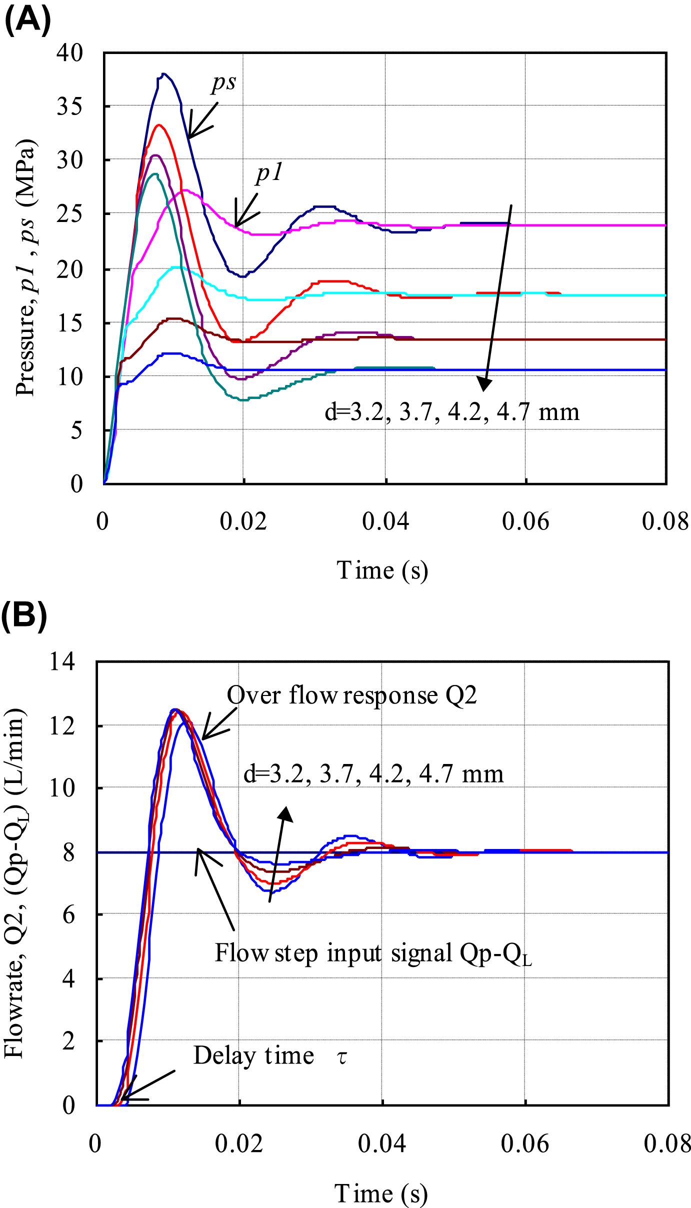
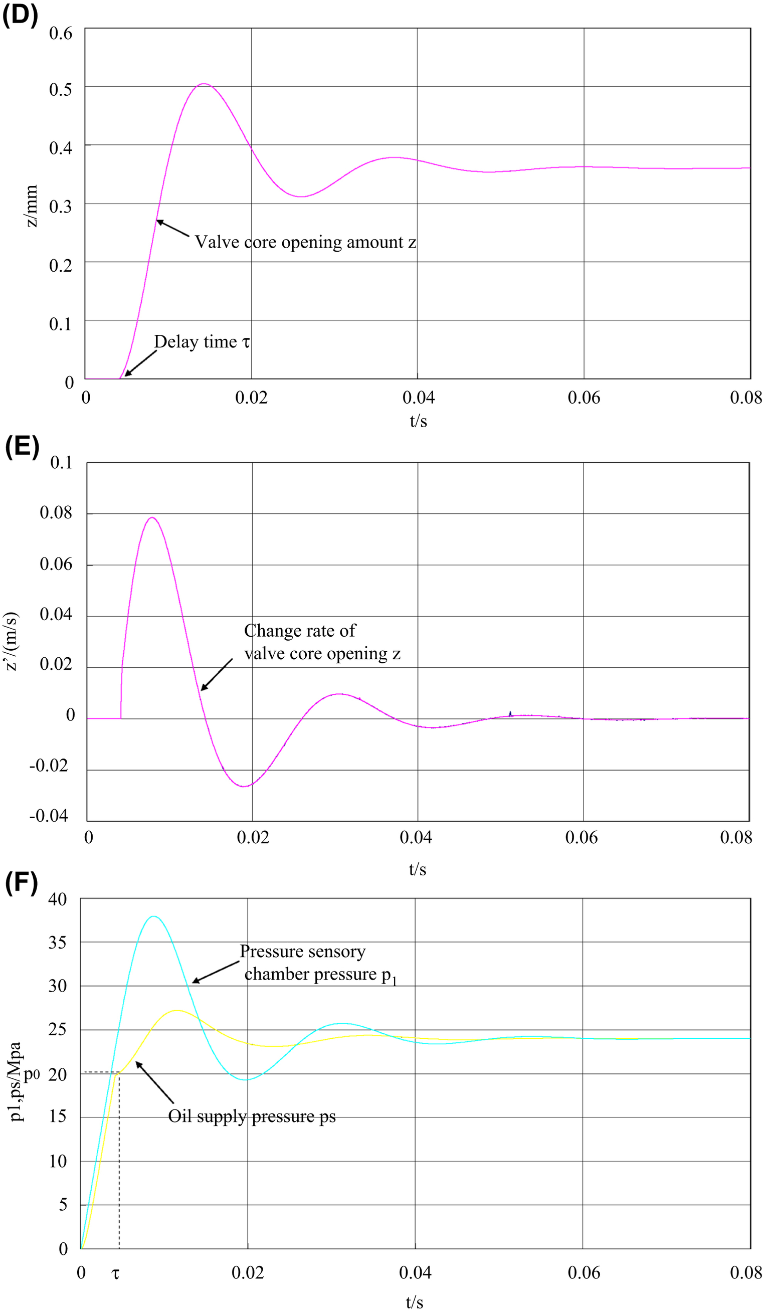
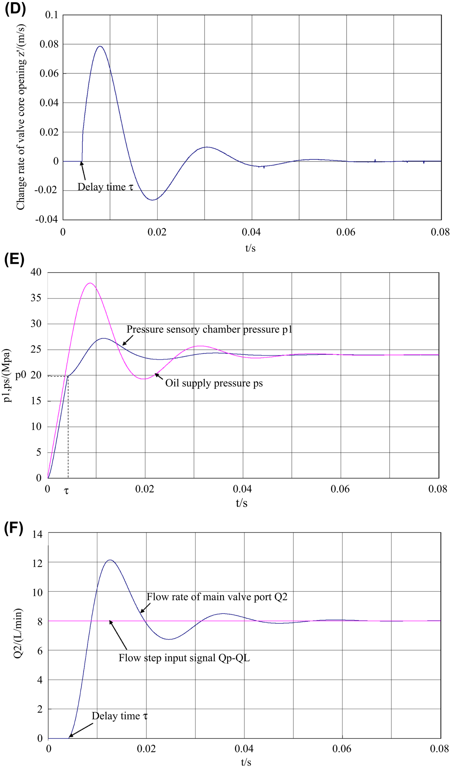
I. Influence of pressure-sensing chamber
Fig. 8.10 shows the influence of the pressure-sensing chamber’s volume on the dynamic characteristics of the overflow valve (8 L/min step flow response curve). As shown in Fig. 8.10A, C and D, before the overflow
valve opens, that is, the overflow valve has a certain delay time τ=0.004s before the valve opening pressure p
10 = 20 MPa. The oil supplied by hydraulic pump is supplied to the chamber between the hydraulic pump and overflow valve, and the pressure is raised due to pseudo-dynamic filling of fluid due to the compressibility of oil. When the overflow valve inlet’s pressure reaches open pressure p
10 = 20 MPa, the valve core begins to move, resulting in a certain displacement, or overflow. The steady-state response time of the overflow valve to the steady working pressure 24 MPa (±3–5%) is 0.03 s. At this point, the optimized size and parameters are the clearance value of balanced piston of h0=5 μm, pressure-sensing chamber volume of V
1 = 19.2 mm3 and work flow Q
2 = 8 L/min. From Fig. 8.10C and D, it can also be seen that the time of the overflow valve core from one position to another position, and finally back to its steady working state, is less than 0.03 s.

II. Influence of the fixed orifice
Fig. 8.11 shows the influence of the size of fixed orifice on the dynamic characteristics of overflow valve (8L/min step flow response curve). The smaller the clearance size of fixed throttle orifice is, the higher the accuracy of manufacturing and assembly, and the shorter the dynamic pressure response time of the overflow valve. At the same time, the balance between noise and dynamic pressure response time should be taken into account.
III. Influence of pressure control chamber
Fig. 8.12 shows the influence of pressure control chamber volume on dynamic characteristics of the overflow valve (8 L/min step flow response curve). The smaller the size of the pressure control chamber is, the shorter the steady-state operation time of the overflow valve, and the less the pressure delay time. The volume of pressure control chamber is composed by the cavity between the hydraulic pump outlet and the overflow valve. The volume of the cavity should be reduced as much as possible in the design of the system.
IV. Influence of valve core conical degree
Fig. 8.13 shows the influence of valve core conical degree on dynamic characteristics of the overflow valve (8 L/min step flow response curve). The taper of the hydraulic valve core influences the dynamic performance of the overflow valve. When the valve core conical degree is larger, the dynamic response of the hydraulic valve is slower, but the delay time is
almost the same. When the diameter of the orifice, overflow rate and work pressure are the same, the greater the taper of valve core, and the greater the displacement of valve core.

V. Influence of piston diameter
Fig. 8.14 shows the influence of the valve path on the dynamic characteristics of the overflow valve (8 L/min step flow response curve). The hydraulic valve path influences the dynamic performance of the overflow valve, when having hydraulic impact of step signal with the same flow rate,
the valve core adopts a larger diameter, the stability time and delay time of hydraulic valve vary little, but the supply pressure is reduced.
8.4. Valve characteristics in vibration environment
According to the mathematical model of the single stage overflow valve with balanced piston and fixed orifice, when a valve is subjected to vibration or impact, the vibration of the valve body is assumed to be y(t), and the positive direction of vibration y is the same as the positive direction of valve core displacement x
v.
8.4.1. Mathematical model of valve before valve core opening in vibration environment
Before the valve core is opened, the valve body moves along with the valve core with the same displacement, speed and acceleration. There is:
where:
According to Newton’s second law, the equation of motion of the valve core is:
where:
The opening condition of the valve is:
That is:
The opening pressure of the valve is:
From Eq. (8.44), it can be seen that when the valve vibration acceleration is negative, the opening pressure of the valve is smaller.
Before the valve core is opened,
p1≤p10
 , the flow equation is:
(8.47)
where:
- p s is the oil supply pressure (Pa);
- Q 1 is the control flow (m3/s);
- Q p is the pump flow (m3/s);
- Q L is the load flow (m3/s);
- V 1 is the pressure-sensing chamber volume (m3);
- V 2 is the pressure control chamber volume (m3);
- h 0 is the fixed orifice clearance (m);
- L is the equivalent damping hole length (m);
- ρ is the oil density (kg/m3); and
- μ is the viscosity coefficient of oil (Pa·s).
where
τ
 is the delay time before the valve core is opened.
8.4.2. Mathematical model of a valve after valve core opening in vibration environment
The valve body is affected by vibration and produces displacement y. As hydraulic oil has compressibility, the opening amount of the main throttling
orifice is reduced to (x
−
y), and the compression amount of the spring is reduced to (x
v
−
y). The kinematical equation of the valve core is:
Steady hydrodynamic and transient hydrodynamic forces are, respectively:
where:
The flow at the main valve port is:
 (8.52)
where:
 (8.58)
where:
8.4.3. Simulation model and dynamic characteristics
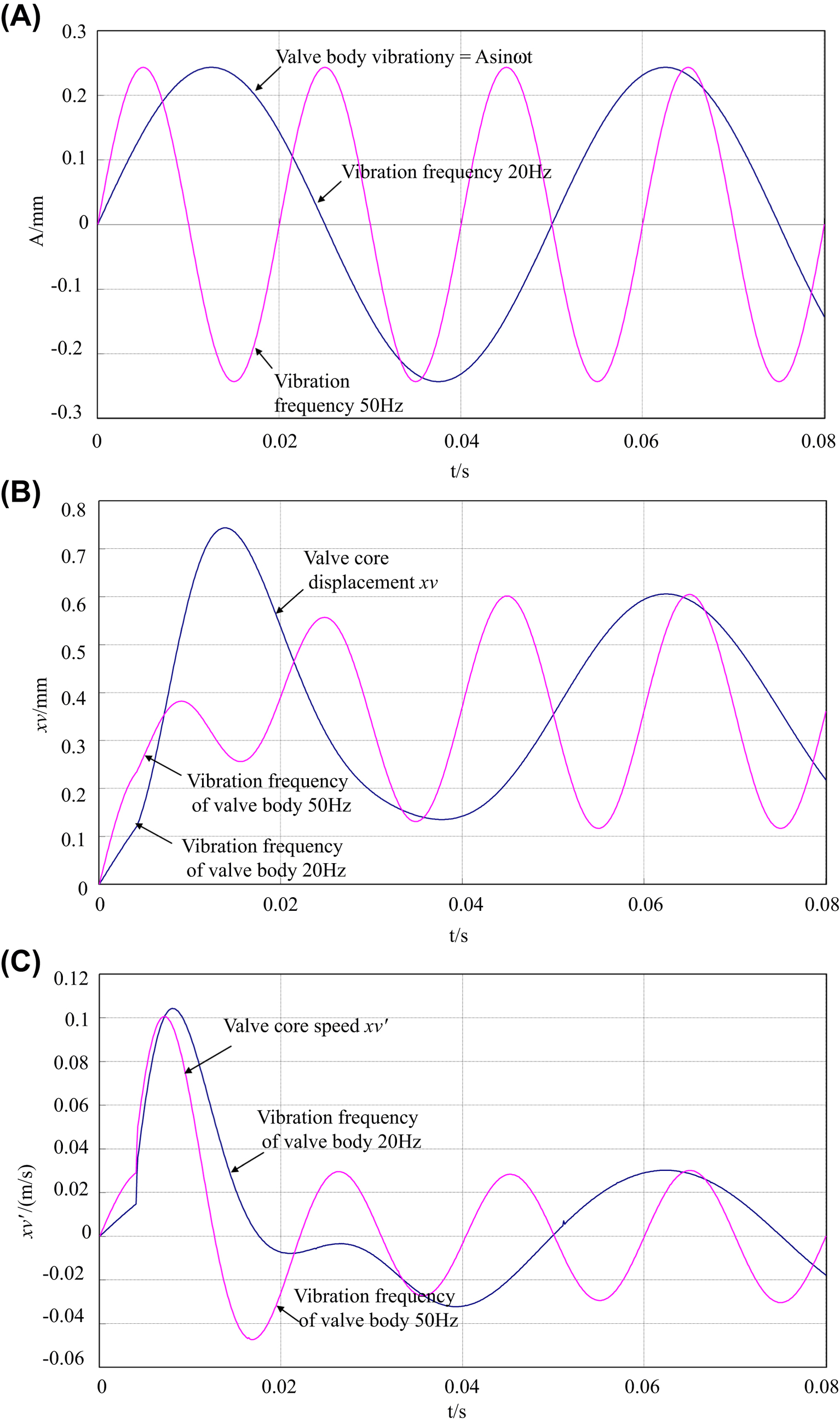
According to Eqs. (8.45)–(8.59), the SIMULINK model of a system under vibration environment is established, a simulation block diagram of SIMULINK model for single stage overflow valve with balanced piston and fixed orifice in vibration environment is set up and the dynamic response is simulated. The structural parameters and fluid parameters of the input valve are input, pressure-sensing chamber volume V
1 = 1.92×10
−8 m3, pressure control chamber volume V
2 = 1.65×10⁻⁵ m3, half cone angle of valve core α=15, fixed orifice clearance h
0
=5μm, valve seat diameter d = 0.0032 m, fluid bulk modulus of elasticity β=6.896×10⁸ Pa and valve core elastic assembly equivalent mass m =0.0012 kg. The initial condition is setting the spring preload kx
0; the step signal is rated flow rate of the overflow valve Q
p – Q
L = 8 L/min; the vibration power spectrum density of the valve body is 0.04 g2/Hz; and the frequency is 20 Hz. Under these conditions, the dynamic curves of supply pressure, pressure in the pressure-sensing chamber, the overflow at the main valve port, the valve core opening, valve core displacement, valve core speed, valve core acceleration and the hydrodynamic force of the valve with time can be obtained.
I. Valve body is subjected to harmonic vibration
The step flow response of the single stage overflow valve with balanced piston and fixed orifice under a sinusoidal vibration environment is shown in Fig. 8.15. It is known that the vibration of the valve body has little influence on the pressure and flow characteristics of a valve. The opening time of the valve core is about 0.004 s and the opening pressure is about 20 MPa. In 0.03 s, the flow and pressure are stable, and the system operating pressure is 24 MPa. After the pressure and flow rate have been stabilized, the valve core and valve body make a simple harmonic vibration at the same frequency.


II. Valve body is subjected to random vibration
Fig. 8.15 shows the step flow response of a single stage overflow valve with balanced piston and fixed orifice under a random vibration environment. The valve body is subjected to random vibration; the power spectrum density of vibration is 0.04 g2/Hz and the frequency range is 20–2000 Hz.
8.4.4. Vibration control measures
In this chapter, a new integrated hydraulic valve, which has a pressure-sensing chamber, pressure control chamber and fixed orifice, has three unique functions: stabilizing pressure, eliminating noise and absorbing vibration. The mathematical model of how to obtain the optimum size of valve core and valve body is given. This new integrated hydraulic valve is very suitable for steady pressure control of a small flow hydraulic system under extreme environment conditions. A single stage overflow valve with balanced piston and fixed orifice, compared with a general spherical valve, or cone valve, has good dynamic performance, and accurate pressure control can be achieved. Through the above analysis, it can be seen that the overflow valve has good anti-vibration and vibration-damping functions. In order to reduce the vibration and noise of the valve further, the following measures can be taken.
- 1. Suitable fixed throttle clearance shall be taken. When the fixed orifice is large, the response time of the overflow valve is shortened. However, the fixed orifice should not be too large, otherwise the valve will vibrate and ‘howl’ during operation.
- 2. Both the stability time and the delay time of the single stage overflow valve with balanced piston and fixed orifice can be shortened when the pressure-sensing chamber and the pressure control chamber are relatively small.
- 3. Increasing the bulk modulus of elasticity of oil is beneficial to improve the stability of valve, so the gas content in the oil should be minimized.
- 4. Increasing spring stiffness or equivalent stiffness, although helpful to increase stability, will affect the static pressure accuracy of static characteristics; moreover, the natural frequency of the valve is generally high, and it is thus difficult to increase the spring stiffness or reduce the mass to improve its natural frequency.
In order to measure the working noise of the hydraulic valve, the working platform of this valve is placed in a separate soundproof room, and noise is detected by a noise meter at a distance of 1 m from the hydraulic test stand. The experimental results show that the working noise of the
common conical valve is 90 dB, and the working noise of the new integrated hydraulic valve is reduced to 62 dB. The conical valve causes vibration of the body easily, but the new integrated hydraulic valve has almost no vibration. The working pressure of the ordinary conical valve is not easy to control, and it is easy to produce the phenomenon of pressure creep in a certain flow; the new integrated hydraulic valve achieves accurate pressure control.
8.5. Influence of operation point of overflow valve on frequency of missile electrohydraulic energy system
In this section, combined with the research of the technology on the influence of overflow valve on the power frequency of electro-hydraulic energy system in a certain missile control cabin, the frequency range of the power supply on the missile at different working points of the overflow valve is analyzed, and the mathematical model of the electro-hydraulic energy system with the power frequency as the main factor under variable load condition of overflow valve is established. By computer numerical calculation, the appropriate overflow valve operating point deviation is determined, and the analysis result has passed the engineering assessment. The method proposed in this chapter is also applicable to the analysis of the influence of factors such as flight height, ambient temperature, gas pressure and missile angle of attack on the frequency of a missile electrohydraulic energy system.
8.5.1. Theoretical analysis
I. Load form
There are three main kinds of hydraulic loads in missile aircraft electrohydraulic energy systems: overflow valve load, servo deck load and seeker antenna load. The relative power ratio of the power load is small, so the dynamic condition of the variable load is not considered here, and the steady state is calculated only in simplified form.
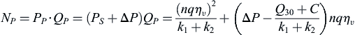
The overflow valve load is:
where:
The null position load of the air cabin is:
where k
2 is the servo mechanism null position flow-pressure coefficient [L/(min·MPa)].
The steady load of the seeker antenna system is:
The hydraulic pump load is:
where:
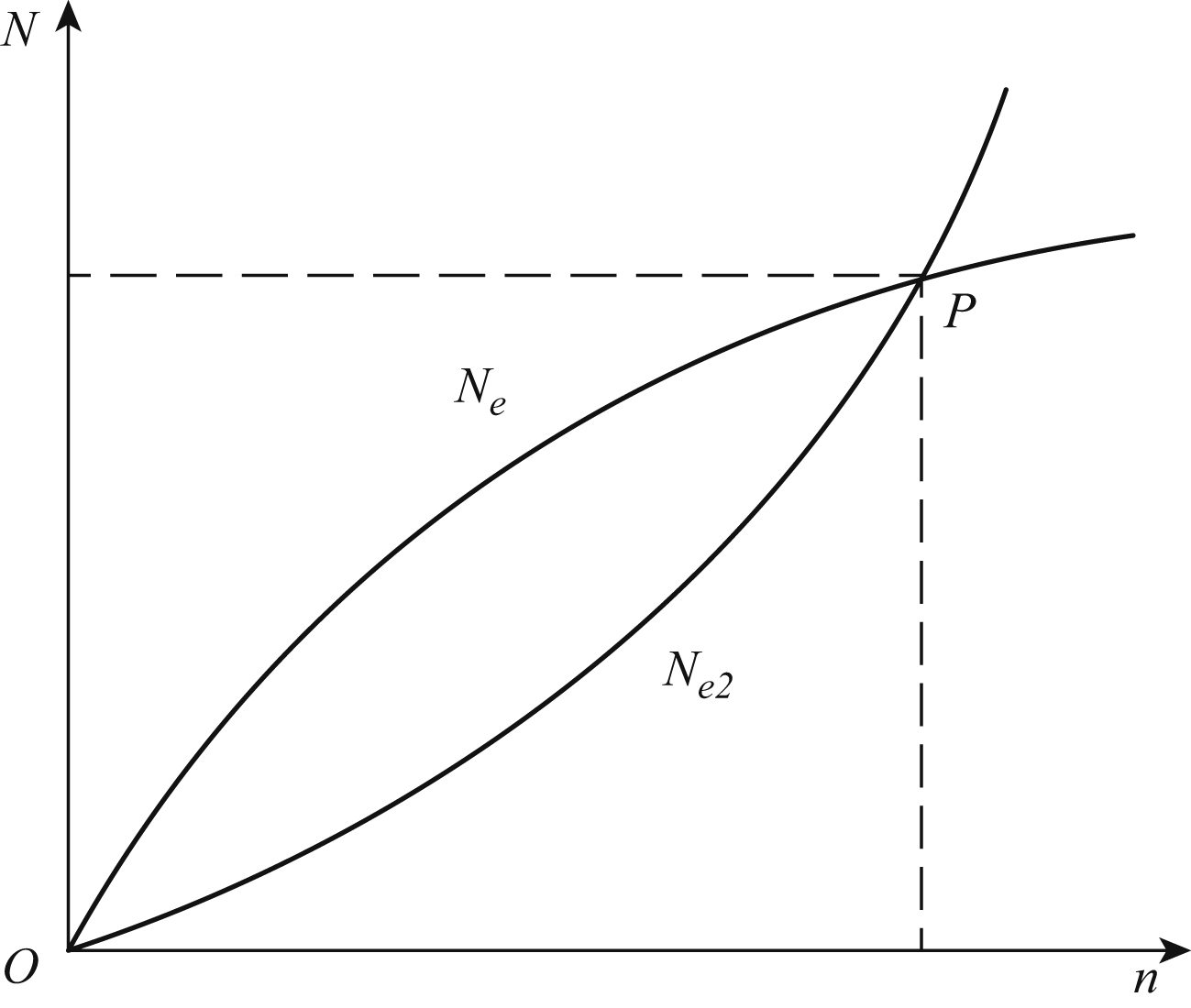
The hydraulic pump output flow is mainly used to meet the needs of the above three types of hydraulic users. As shown in Fig. 8.17, when the hydraulic pump speed is constant, the output flow is basically the same. At this point, the integrated load flow determined by Eqs. (8.60)–(8.62) matches, and curve n
1 is automatically balanced with curve n
2 and works at the intersection of A(p
A, Q
A). When the hydraulic pump speed rises, the flow rate increases and work point is balanced. The hydraulic system works at the intersection of B(p
B, Q
B); when the load curve is changed from p
1 to p
2, the operating point is at the intersection of C(p
C, Q
C); when the hydraulic pump speed is changed from n
1 to n
2, the load curve is changed from p
1 to p
2, and the operating point is at the intersection of D(p
D, Q
D).

The flow continuity equation of the hydraulic system is:
It can be obtained as follows:
Considering pipeline loss, the actual output power of the hydraulic pump is:
 (8.65)
The output power of the power supply is approximately:
where:
The relation between power frequency and motor speed of the power supply device is as follows:
II. Energy balance
The gas turbine directly drives the motor to output power, and simultaneously drives the hydraulic pump with a coaxial connection to output hydraulic energy. When the system design is properly matched, as shown in Fig. 8.18, the gas turbine can drive load – that is, output power is consistent with load demand to achieve automatic balance. At this time, the working state rated condition.
Electro hydraulic energy requires the gas turbine output power to be:
 (8.68)
The gas turbine power balance equation is:
III. Influence of operation point change of overflow valve
After the completion of structural design, the slope of the pressure flow characteristic curve of the overflow valve is basically determined. When the scheduled operation point of the overflow valve changes, this only affects the C value in Eq. (8.60). At different work points or work point deviations, there are different C values, while the slope value k
1 is basically unchanged. It is known from Eqs. (8.67)–(8.69) that the system has different power output frequency values f when work points or work point deviations are different.
8.5.2. Numerical calculation and its programme
I. Numerical calculation programme
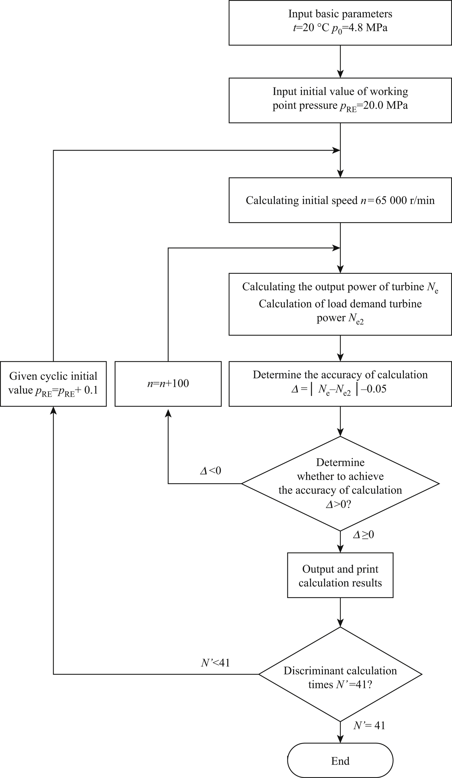
According to the mathematical model and basic parameters of Eqs. (8.60)–(8.69), the calculation programme of the gas turbine can be established. That is, the output power is calculated at different speeds, and the expected load output power of the gas turbine is calculated at the same speed. According to the power balance, after two side approximation numerical calculations, the error discrimination is made.
The calculation cycle is set at different working points, and the output result is as follows: overflow valve operation point, output power frequency. A flowchart of the calculation programme is shown in Fig. 8.19.
II. Parameters setting
According to the structural parameters and experimental results, taking an aircraft as an example, the values of each parameter in the programme are selected as follows:
Ambient temperature t = 20°C, gas pressure p
0 = 4.8MPa, k
1 = 3.401, k
2 = 0.063, Q
30 = 2, Δp = 1, η
m = 0.8, η
v = 0.95, q = 1, η
d = 0.75, k
d = 1.95×10⁻⁸.
The flow rate at the working point of the overflow valve is Q
L = 8 L/min, the calculation range of working pressure p
RE = 20–24 MPa and the operating cycle parameter of the overflow valve is:
III. Results analysis
The calculation results are shown in Fig. 8.20. When the change amount of the overflow valve operating point is Δp = ±0.5 MPa, the frequency range of the power supply is Δf =
∓
 23 Hz. When the change amount of the overflow valve operating point is reduced to Δp = ±0.2 MPa, the frequency range of the power supply is Δf =
∓
9 Hz. It can be seen that controlling the deviation range of the working point of relief valve will greatly reduce its influence on the output frequency of power supply.
8.5.3. Technological measures
1. Debugging technology
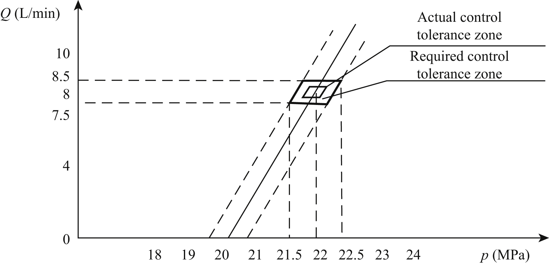
In order to control the pressure deviation of the overflow valve working point from original ±0.5 MPa to ±0.2 MPa, during the process of manufacturing and debugging, according to the requirements of product control tolerance zone shown in Fig. 8.21, the following measures should be taken:
- 1. Running-in process. The product runs under the condition of oil flow and high pressure, and adaptability and matching quality of each working pair in overflow valve are increased. The static and dynamic joint surfaces of valve inner surface are mutually jointed. Running-in time is 5–10 min.
- 2. Coarse adjustment process. Operating point coarse adjustment is in the range of ±0.5 MPa, and operates at the work point for 3–5 min.
- 3. Fine adjustment process. Inching control valve operation point, and carries on three work cycle condition tests, placing the work point in the range of ±0.2 MPa.

2. Hot-air blowing test and ignition test of gas electrohydraulic energy system
- 1. The operating point deviations of the overflow valve used in some products of a gas turbine pump electrohydraulic energy system for an aircraft are within ±0.2 MPa, and the overflow valve is installed in a control tank electrohydraulic energy system. After the vibration and temperature shock process, the simulation check of hot-air blowing is carried out. The gas turbine pump electrohydraulic energy system is driven by hot gas, and the pressure is controlled by the overflow valve. The results are shown in Table 8.1. Apart from the change of working hot gas pressure, the valve operating point affecting the frequency range is within the range of calculation and analysis.
- 2. High and low temperature ignition tests of an electrohydraulic energy system for an aircraft: an overflow valve with a small working point deviation is used for test working pressure. Through various environmental conditions and ignition tests together with the system, the overflow valve can work properly during the whole process. After the test, the parameters of the working point are almost unchanged.
8.5.4. Conclusions
- 1. The operation point of the overflow valve is the key factor affecting the working frequency of a missile electrohydraulic energy system. By establishing a mathematical model and using the power bilateral approximation numerical calculation method, the working frequency of power supply under variable load condition is calculated, and the appropriate working point deviation and load variation range are determined.
- 2. The work point deviation of the overflow valve can be reduced by manufacturing process control. Taking the work of running-in, the coarse and fine tuning process, and the three cycle work point test method, the overflow valve’s operating point can be controlled from 22±.±0.5 MPa, 8±0.5 L/min to 22±±0.2 MPa and 8±.0.2 L/min – that is, the influence of single factor overflow valve load on power frequency range is reduced from ±23 Hz to ±9 Hz.
-
Table 8.1
Hot-air blowing test and ignition test results of gas turbine pump electrohydraulic energy system for an aircraft Cabin no. Hot-air pressure Overflow working point System pressure Power frequency YZD-01 5.16–5.29 22.0 7.99 21.38–21.5 294–303 YZD-02 4.8–5.07 22.23 8.10 21.26–21.3 302–326.6 YZD-03 5.6–6.4 22.77 7.95 21.7–21.76 317.3–335.3 YZD-04 4.9–5.1 21.93 7.99 21.5–21.6 300–315 YZD-05 5.6–6.75 21.93 8.10 21.6–21.78 309–389 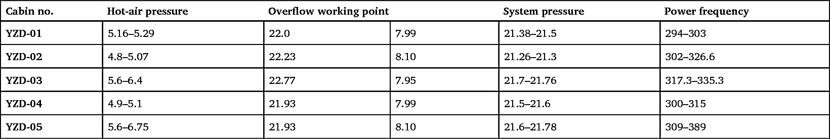
- 3. The analysis and research results have been applied to certain aircraft products and documents, and have been tested in the manufacturing process and system test be in engineering.
- 4. The proposed method is also applicable to the analysis of the influence of missile altitude, ambient temperature, gas pressure and missile angle of attack on the power frequency of a missile.
..................Content has been hidden....................
You can't read the all page of ebook, please click here login for view all page.