
Chapter 12
Acquiring Additional Parts
IN THIS CHAPTER
![]() Choosing the perfect type of wire
Choosing the perfect type of wire
![]() Powering up with batteries and solar cells
Powering up with batteries and solar cells
![]() Controlling connections with switches
Controlling connections with switches
![]() Triggering circuits with sensors
Triggering circuits with sensors
![]() Turning electricity into light, sound, and motion
Turning electricity into light, sound, and motion
Although the individual components and integrated circuits discussed in Chapters 4 through 11 form the A-team when it comes to shaping the flow of electrons in electronic circuits, there are a bunch of other contributing parts that the A-team relies on to help get the job done.
Some of these other parts — such as wires, connectors, and batteries — are essential ingredients in any electronic circuit. After all, you’d be hard-pressed to build an electronic circuit without wires to connect things or a source of power to make things run. As for the other parts I discuss in this chapter, you may use them only now and then for certain circuits. For example, when you need to make some noise, a buzzer sure comes in handy — but you may not want to use one in every circuit you build.
In this chapter, I discuss a mixed bag of components, some of which you should keep in stock (just like toilet paper and toothpaste), while the others can be picked up whenever the spirit moves you.
Making Connections
Making a circuit requires that you connect components to allow electric current to flow between them. The following sections describe wires, cables, and connectors that allow you to do just that.
Choosing wires wisely
Wire that you use in electronics projects is just a long strand of metal, usually made of copper. The wire has only one job: to allow electrons to travel through it. However, you can find a few variations in the types of wire available to you. In the following sections, I give you the lowdown on which type of wire to choose for various situations.
Stranded or solid?
Cut open the cord of any old household lamp (only after unplugging the lamp, of course), and you see two or three small bundles of very fine wires, each wrapped in insulation. This is called stranded wire. Another type of wire, known as solid wire, consists of a single (thicker) wire wrapped in insulation. You can see examples of stranded and solid wires in Figure 12-1.
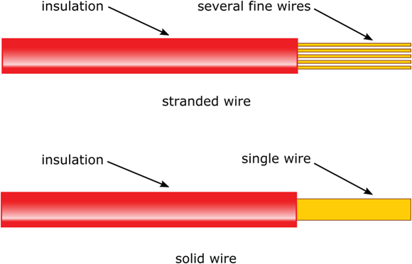
FIGURE 12-1: Both stranded and solid wire are commonly used in electronics.
Stranded wire is much more flexible that solid wire, and you use it in situations in which the wire will be moved or bent a lot (such as in line cords for lamps and the cables you hook up to your home entertainment system). You use solid wire in places where you don’t plan to move the wire around, and to connect components on breadboards (check out Chapter 15 for more on breadboards). It’s easy to insert solid wire into holes in the breadboard, but if you try to use a stranded wire, you have to twist the strands to get all of them into the hole, and you may break a strand or two in the process (trust me — it happens), which could short out the circuit.
Sizing up your wire gauge
You refer to the diameter of wire as the wire gauge. As luck would have it, the relationship between wire gauge and wire diameter in electronics is essentially backward: The smaller the wire gauge, the larger the wire diameter. You can see common wire gauges in Table 12-1.
TABLE 12-1 Wires Commonly Used in Electronics Projects
Wire Gauge |
Wire Diameter (inches) |
Uses |
16 |
0.051 |
Heavy-duty electronics applications |
18 |
0.040 |
Heavy-duty electronics applications |
20 |
0.032 |
Most electronics projects |
22 |
0.025 |
Most electronics projects |
30 |
0.01 |
Connections on small circuit board prototypes or wire-wrap connections |
For most electronics projects, including the ones in this book, you use 20- or 22-gauge wire. If you’re hooking up a motor to a power supply, you need to use 16- or 18-gauge wire. You may find smaller 28- or 30-gauge wire useful for making connections on small circuit board prototypes. 30-gauge wire was commonly used for connecting components on special circuit boards using a technique known as wire wrapping, which is rarely done anymore. (Refer to Chapter 15 for details on circuit construction.)
 You sometimes see gauge abbreviated in weird and wonderful ways. For example, you may see 20 gauge abbreviated as 20 ga., #20, or 20 AWG (American Wire Gauge).
 If you start working on projects involving higher voltage or current than the ones described in this book, consult the instructions for your project or an authoritative reference to determine the appropriate wire gauge. For example, the National Electrical Code lists the required wire gauges for each type of wiring that you use in a house. Make sure that you also have the right skills and sufficient knowledge of safety procedures to work on such a project.
The colorful world of wires
As with the colorful bands that unlock the secrets of resistor values, the colorful insulation around wire can help you keep track of connections in a circuit. When wiring a DC circuit (for example, when you work with a breadboard), using red wire for all connections to positive voltage (+V) and black wire for all connections to negative voltage (–V) or to ground is common practice. For AC circuits, use green wire for ground connections. Yellow or orange wire is often used for input signals, such as the signal from a microphone into a circuit. If you keep lots of different colors of wire handy, you can color-code your component connections so it’s easier to tell what’s going on in a circuit just by glancing at it (unless, of course, you’re colorblind).
Collecting wires into cables or cords
Cables are groups of two or more wires protected by an outer layer of insulation. Line cords that bring AC power from a wall outlet to an electrical device such as a lamp are cables — so are the cords in the mishmash of connections in your home entertainment system. Cables differ from stranded wires because the wires used in cables are separated by insulation.
Plugging in to connectors
If you look at a cable — say, the one that goes from your set-top box to your TV— you see that it has metal or plastic doodads on each end. These doodads are called plugs, and they represent one kind of connector. There are also metal or plastic receptacles on your set-top box and TV that these cable ends fit into. These receptacles (sometimes called sockets or jacks) are another kind of connector. The various pins and holes in connectors connect the appropriate wire in the cable to the corresponding wire in the device.
Different types of connectors are used for various purposes. Among the connectors you’re likely to hook up with in your electronics adventures are these:
- A terminal and terminal block work together as the simplest type of connector. A terminal block contains sets of screws in pairs. You attach the block to the case or chassis of your project. Then, for each wire you want to connect, you solder (or crimp) a wire to a terminal. Next, you connect each terminal to a screw on the block. When you want to connect two wires, simply choose a pair of screws and connect the terminal on each wire to one of those screws.
- Plugs and receptacles carry audio and video signals between pieces of equipment that have cables like the ones you see in Figure 12-2. Plugs on each end of the cable connect to receptacles on the equipment being connected. Analog audio cables (see Figure 12-2, left) contain one or two signal wires (which carry the audio signal) and a metal shield surrounding the wires. The metal shield protects the signal wires from electrical interference (known as noise) by minimizing the introduction of stray current into the wires. Digital multimedia cables, such as the High-Definition Multimedia Interface (HDMI) cable on the right in Figure 12-2, contain multiple shielded wires that carry digital audio and video data.
- You typically use pin headers to bring signals to and from circuit boards, which are thin boards designed to house a permanent circuit. Pin headers come in handy for complex electronics projects that involve multiple circuit boards. Most pin headers consist of one or two rows of metal posts attached to a block of plastic that you mount on the circuit board. You connect the pin header to individual or bundled wires, or to a compatible connector at the end of a ribbon cable — a series of insulated wires stuck together side by side to form a flat, flexible cable. The rectangular shape of the connector allows easy routing of signals from each wire in the cable to the correct part of the circuit board. You refer to pin headers by the number of pins (posts) they use, such as a 40-pin header.
Electronics uses a wealth of connectors that you don’t have to delve into until you start doing more complex projects. If you want to find out more about the broad array of connectors, you can take a look at some of the catalogs or websites of electronics suppliers listed in Chapter 19. Most devote an entire category of products to connectors.

FIGURE 12-2: An analog audio cable (left) and an HDMI cable (right) facilitate the transmission of information between two pieces of electronic equipment.
Powering Up
All the wires and connectors in the world won’t do you much good if you don’t have a power source. In Chapter 3, I discuss sources of electricity, including AC power from wall outlets and DC power from batteries and solar cells (also known as photovoltaic cells). Here I discuss how to choose a power source and how to feed its power into your circuits.
Turning on the juice with batteries
For most hobby electronics projects, cells or batteries — which are combinations of cells — are the way to go. The symbols used to represent a cell and a battery in a circuit diagram are shown in Figure 12-3.
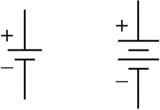
FIGURE 12-3: Circuit symbols for a cell (left) and a battery (right).
Many schematics use the symbol for a cell to represent a battery. Cells are relatively lightweight and portable, and by combining multiple cells in series, you can create a variety of DC voltage sources. Everyday cells, such as garden-variety AAA-, AA-, C-, and D-cells, all produce about 1.5 volts each. A 9-volt battery (sometimes called a transistor battery or PP3 battery) is shaped like a 3-D rectangle and ordinarily contains six 1.5-volt cells. (Some cheap brands may contain only five 1.5-volt cells.) A lantern battery (a big boxy thing that can power a flashlight the size of a boom box) produces about 6 volts.
Connecting batteries to circuits
You use a 9-volt (PP3) battery clip (shown in Figure 12-4) to connect an individual 9-volt battery to a circuit. Battery clips snap onto the terminals of the battery (those snaps on the top of the battery are known as a PP3 connector); they contain black and red leads that you connect to your circuit. You strip the insulation from the ends of the black and red wires, and then connect the leads (the bare ends) to your circuit. You can connect the leads to terminals, insert them into holes in a breadboard, or solder them directly to components. I discuss all these techniques in Chapter 15.

FIGURE 12-4: A battery clip makes it easy to connect a 9-volt battery to your circuit.
When you connect the positive terminal of one battery to the negative terminal of another battery, the total voltage across this series connection is the sum of the individual battery voltages.
Battery holders make series connections between batteries for you while holding multiple batteries in place. Some battery holders provide red and black leads for access to the total voltage; others, such as the one in Figure 12-5, provide PP3 connector snaps so you can attach a battery clip and access the total voltage across the clip’s red and black leads.

FIGURE 12-5: Four 1.5 volt batteries in a battery holder produce about 6 volts across the red and black leads.
Sorting batteries by what’s inside
Batteries are classified by the chemicals they contain, and the type of chemical determines whether a battery is rechargeable. The following types of batteries are readily available:
- Disposable (non-rechargeable) batteries:
- Zinc-carbon batteries come in a variety of sizes (AAA, AA, C, D, and 9 volt, among others) and are at the low end of the battery food chain. They don't cost much, but they also don’t last long.
- Alkaline batteries also come in a variety of sizes, and last about three times as long as zinc-carbon batteries. I suggest starting with this type of battery for your projects. If you find yourself replacing them often, you can step up to rechargeable batteries.
- Lightweight lithium batteries generate higher voltages — about 3 volts — than other types and have a higher current capacity than alkaline batteries. They cost more, and you can’t recharge most lithium batteries, but you can’t beat ’em when your project (for instance, a small robot) calls for a lightweight battery.
- Rechargeable batteries:
- Nickel-metal hydride (NiMH) batteries are the most popular type of rechargeable batteries today. They come in a variety of sizes (AAA, AA, C, D, and 9 volt) and generate about 1.2 volts. One drawback to NiMH batteries is that they self-discharge over a few months if not used, but some low self-discharge NiMH battery models are available. I suggest you use NiMH batteries for projects that need rechargeable batteries.
- Lithium-ion (Li-ion) batteries are the newest type of rechargeable battery. Most generate a nominal 3.7 volts and a maximum 4.2 volts, and all require a special charger (an NiMH charger will not work). Although some models look like your run-of-the-mill AA or AAA batteries, Li-ion batteries use a different naming convention (for instance, a 14500 Li-ion battery is the same size as an AA battery). If you choose to use Li-ion batteries, bear in mind the voltage differences between these batteries and conventional cells. (For instance, two Li-ion batteries in series generate 7.4 V while two AA batteries in series generate 3.0 V.)
- Nickel-cadmium (NiCd) batteries, like NiMH batteries, generate about 1.2 volts. NiCds (pronounced “NYE cads”) have declined drastically in popularity since their heyday in the mid-1990’s, due to their poor capacity, their toxic content (cadmium), improvements in other battery technologies (particularly NiMH), and a flaw NiCds exhibit known as the memory effect, which requires you to fully discharge the battery before recharging it, to ensure that it recharges to its full capacity. I recommend you steer clear of NiCd batteries — unless you happen to have some lying around and want to get your money’s worth.
Be careful not to mix battery types in the same circuit, and never attempt to recharge disposable batteries. These batteries can rupture and leak acid, or even explode. Most disposable batteries contain warnings about the dangers of such misuse right on their labels.
Buying a recharger and a supply of rechargeable batteries can save you a considerable amount of money over time. Just make absolutely sure the battery charger you use is designed for the type of rechargeable battery you select. Check both the chemistry (for instance, Li-ion or NiMH) and the voltage of the battery when selecting a charger.
Be sure to dispose of batteries properly. Batteries containing heavy metals (such as nickel, cadmium, lead, and mercury) can be hazardous to the environment when improperly disposed. For guidelines on proper disposal — which may vary from state to state — check battery manufacturer websites or other websites, such as www.ehso.com/ehshome/batteries.php.
Getting power from the sun
If you’re building a circuit designed to operate outside — or you just want to use a clean, green source of energy — you may want to purchase one or more solar panels. A solar panel consists of an array of solar cells (which are large diodes known as photodiodes) that generate current when exposed to a light source, such as the sun. (I discuss diodes in Chapter 9, and photodiodes in the section “Using Your Sensors,” later in this chapter.) A panel measuring about 5 x 5 inches may be able to generate 100 milliamps at 5 volts in bright sunlight. If you need 10 amps, you can certainly get it, but you may find the size of the panel problematic — and expensive — for a small or portable project.
Some solar panels contain output leads that you can connect into your circuit, much like the leads from a battery clip or battery holder. Other solar panels have no leads, so you have to solder your own leads to the two terminals.
Here are some criteria to consider to help you determine whether a solar panel is appropriate for your project:
- Do you plan to have the solar panel in sunlight when you want your circuit to be on, or use the panel to charge a storage battery that can power your project? If not, look for another power source.
- Will the solar panel fit on the gadget you’re building? To answer this question, you need to know how much power your gadget will need and the size of the solar panel that can deliver enough power. If the panel is too large for your gadget, either redesign the gadget to use less power or look for another power source.
Using wall power to supply higher DC current or voltage (not recommended)
The AC power supplied by your utility company can cause injury or death if used improperly, so I don’t recommend that you power circuits directly off household current. And because the vast majority of hobby electronics projects run on batteries, you may never be tempted to work with AC anyway.
Some projects need more DC current or higher DC voltages than batteries can easily provide. In those cases, you can use an AC adapter, such as the one shown in Figure 12-6, to convert AC to DC and get the higher current or voltage you need. All the working parts are self-contained in the wall transformer, so you aren't exposed to high AC currents.

FIGURE 12-6: This AC adapter converts 120 volts AC to 7.5 volts DC and supplies up to 300 mA of current. I modified the output of this adapter to make it easier to use in DC circuits.
Under no circumstances should you pry apart the plastic housing for the circuitry inside an AC adapter. Capacitors inside the housing store significant electrical charge. (Refer to Chapter 7 for details on capacitors.)
AC adapters supply currents ranging from hundreds of milliamps to a few amps at voltages ranging from 5 volts DC to 20 volts DC. Some provide both a positive DC voltage and a negative DC voltage. Different models use different types of connectors to deliver power. If you purchase an AC adapter, be sure to read the specification sheet (specs) carefully to determine its power rating and how to connect it to your circuit.
You may want to prepare your AC adapter for easy use in your circuits by removing its output plug and separating and stripping the two output leads so that you can connect the leads directly to your circuit to supply DC voltage (as shown in Figure 12-6, right). Here are the steps to follow to prepare your adapter:
- Make sure the AC adapter is not plugged in to an AC outlet.
- Using your wire cutters (refer to Chapter 13), cut off the output connector.
- Using a utility knife (or your fingernails), separate the two insulated wires along a distance of roughly two inches.
Using your wire cutters, cut one of the two insulated wires so that it is at least an inch shorter than the other wire.
By making one wire shorter that the other, you prevent the two wires from accidentally coming into contact when the AC adapter is powered up, which would short out the adapter, rendering it useless.
- Using your wire strippers (refer to Chapter 13), carefully strip the insulation off each of the two wires along a half-inch length.
- Twist the stranded copper wires of each conductor so that there are no loose strands.
- Making sure the two conductors are not touching each other, plug the AC adapter into an AC outlet.
- Set your multimeter to measure DC volts with a range of 20 V or more (refer to Chapter 16), and place one multimeter lead on one AC adapter output wire and the other multimeter lead on the other output wire.
Observe the voltage reading.
If the voltage reading is positive, your positive (usually red) multimeter lead is attached to the positive conductor of the AC adapter. If the voltage reading is negative, your negative (usually black) multimeter lead is attached to the positive conductor of the AC adapter. Label the positive conductor with a marker or by attaching a label.
Note that the magnitude of the voltage reading you get is likely significantly higher than the nominal voltage specified on the label or data sheet of the AC adapter. This discrepancy is normal and due to the fact that you are using an unregulated power supply and measuring the adapter’s output voltage under no-load conditions. Unregulated power supplies generate voltages that vary depending on the current drawn by the load, that is, the device receiving power. After you connect the adapter’s output leads to a circuit, the output voltage will come down. I measured 10.5 V on an AC adapter that was labeled 7.5 VDC (volts DC).
Congratulations! You now have a power supply for your electronics projects that can supply more current that batteries can provide.
Even after you remove your AC adapter from your wall power, you'll still find a DC voltage across the output leads for quite a while because there is a large capacitor inside the housing that is holding its charge. The capacitor will eventually discharge, but it could take hours. To discharge the capacitor quickly, use your insulated needle-nose pliers to grip a 680 Ω resistor, carefully maneuver the pliers to place the resistor’s leads across the AC adapter’s output leads, and wait about 30 seconds.
Using Your Sensors
When you want to trigger the operation of a circuit as a response to something physical happening (such as a change in temperature), you use electronic components known as sensors. Sensors take advantage of the fact that various forms of energy — including light, heat, and motion — can be converted into electrical energy. Sensors are a type of transducer, which is an electronic device that converts energy from one form to another. In this section, I describe some of the more common input transducers, or sensors, used in electronic circuits.
The circuit symbols for several types of sensors discussed in this section are shown in Figure 12-7.

FIGURE 12-7: Circuit symbols for a variety of sensors.
Seeing the light
Many electronic components behave differently depending on the light they are exposed to. Manufacturers make certain versions of components to exploit this light sensitivity, enclosing them in clear cases so you can use them as sensors in equipment such as burglar alarms, smoke detectors, automatic dusk-to-dawn lighting, and safety devices that stop your electrically controlled garage door from descending when a cat runs under it. You can also use them for communications between your remote control, which sends coded instructions via infrared light using a light-emitting diode (LED, which I discuss in Chapter 9), and your TV or DVD player, which contains a light-sensitive diode or transistor to receive the coded instructions.
Examples of light-sensitive devices used as sensors include the following:
- Photoresistors (or photocells) are light-dependent resistors (LDRs) made from semiconductor material. They typically exhibit a high resistance (about 1 MΩ) in darkness and a fairly low resistance (about 100 Ω) in bright light, but you can use a multimeter (as I describe in Chapter 16) to determine the actual resistances exhibited by a specific photoresistor. The typical photoresistor is most sensitive to visible light, especially in the green-yellow spectrum. A photoresistor can be installed with current running either way in your circuits.
- Photodiodes are sort of the opposite of light-emitting diodes, which I discuss in Chapter 9. They conduct current or drop voltage only when exposed to sufficient light, usually in the infrared (not visible) range. Like standard diodes, photodiodes contain two leads: The shorter lead is the cathode (negative end) and the longer lead is the anode (positive end).
- Most phototransistors are simply bipolar junction transistors (as I discuss in Chapter 10) that are encased in a clear package so that light biases the base-emitter junction. These devices usually contain only two leads (whereas standard transistors contain three leads). That’s because you don’t need access to the base of the transistor to bias it — light does that job for you. From the outside, phototransistors look just like photodiodes, so you really have to keep track of which is which.
Capturing sound with microphones
Microphones are input transducers that convert acoustic energy (otherwise known as sound) into electrical energy. Most use a thin membrane, or diaphragm, that vibrates in response to air pressure changes from sound. The vibrations of the membrane are translated into an AC electrical signal in various ways, depending on the type of microphone:
- In a condenser microphone, the vibrating membrane plays the role of one plate of a capacitor, so that variations in sound produce corresponding variations in capacitance. (For more about capacitors, see Chapter 7.)
- In a dynamic microphone, the diaphragm is attached to a movable induction coil located inside a permanent magnet. As sound moves the diaphragm, the coil moves inside the magnetic field produced by the magnet, and a current is induced in the coil. (Chapter 8 has the lowdown on this phenomenon, which is known as electromagnetic induction.)
- In a crystal microphone, a special piezoelectric crystal is used to convert sound into electrical energy, taking advantage of the piezoelectric effect, in which certain substances produce a voltage when pressure is applied to them.
- In a fiber-optic microphone, a laser source directs a light beam toward the surface of a tiny reflective diaphragm. As the diaphragm moves, changes in light reflected off the diaphragm are picked up by a detector, which transforms the differences in light into an electrical signal. Fiber-optic microphones are immune to both electromagnetic interference (EMI) and radio frequency interference (RFI).
Feeling the heat
A thermistor is a resistor whose resistance value changes with changes in temperature. Thermistors have two leads and no polarity, so you don’t need to worry about which way you insert a thermistor into your circuit.
Following are the two types of thermistors:
- Negative temperature coefficient (NTC) thermistor: The resistance of an NTC thermistor decreases with a rise in temperature. This type of thermistor is the more common one.
- Positive temperature coefficient (PTC) thermistor: The resistance of an PTC thermistor increases with a rise in temperature.
Suppliers’ catalogs typically list the resistance of thermistors as measured at 25 degrees Celsius (77° F). Measure the resistance of the thermistor yourself with a multimeter at a few different temperatures (see Chapter 16 for more about using multimeters). These measurements enable you to calibrate the thermistor, or get the exact relationship between temperature and resistance. If you’re not sure of a thermistor’s type, you can figure that out by identifying whether the value increases or decreases with a rise in temperature.
If you’re planning to use the thermistor to trigger an action at a particular temperature, be sure to measure the resistance of the thermistor at that temperature.
More energizing input transducers
Many other types of input transducers are used in electronic circuits. Here are three common examples:
- Antennas: An antenna senses electromagnetic waves, and transforms the energy into an electrical signal. (It also functions as an output transducer, converting electrical signals into electromagnetic waves.)
- Pressure or position sensors: These sensors take advantage of the variable-resistance properties of certain materials when they undergo a deformation. Piezoelectric crystals are one such set of materials.
- Accelerometers: One type of accelerometer that detects your smartphone orientation relies on variations in capacitance that result when acceleration forces move one tiny capacitive plate attached to a spring relative to a fixed plate.
Transducers are often categorized by the type of energy conversion they perform, for instance, electroacoustic, electromagnetic, photoelectric, and electromechanical transducers. These amazing devices open up tremendous opportunities for electronic circuits to perform countless useful tasks.
Experiencing the Outcome of Electronics
Sensors, or input transducers, take one form of energy and convert it into electrical energy, which is fed into the input of an electronic circuit. Output transducers do the opposite: They take the electronic signal at the output of a circuit and convert it into another form of energy — for instance, sound, light, or motion (which is mechanical energy).
You may not realize it, but you’re probably familiar with many devices that really are output transducers. Light bulbs, LEDs, motors, speakers, liquid crystal displays (LCDs), and other electronic visual displays all convert electrical energy into some other form of energy. Without these puppies, you might create, shape, and send electrical signals around through wires and components all day long, and never reap the rich rewards of electronics. It’s only when you transform the electrical energy into a form of energy you can experience (and use) that you begin to enjoy the fruits of your labor.
The schematic symbols for three output transducers discussed in this section are shown in Figure 12-8.

FIGURE 12-8: Circuit symbols for some popular output transducers.
Speaking of speakers
Speakers convert electrical signals into sound energy. Most speakers consist simply of a permanent magnet, an electromagnet (which is a temporary, electrically controlled magnet), and a vibrating cone. Figure 12-9 shows how the components of a speaker are arranged.

FIGURE 12-9: The parts of a garden-variety speaker: two magnets and a cone.
The electromagnet, which consists of a coil wrapped around an iron core, is attached to the cone. As electrical current alternates back and forth through the coil, the electromagnet gets pulled toward and then pushed away from the permanent magnet. (Chapter 8 tells you more about the ups and downs of electromagnets.) The motion of the electromagnet causes the cone to vibrate, which creates sound waves.
Most speakers come with two leads that can be used interchangeably. For more serious projects, such as speakers in stereo systems, you must pay attention to the polarity markings on the speakers because of the way they are used in electronic circuits inside the stereo system.
Speakers are rated according to the following criteria:
- Frequency range: Speakers can generate sound over different ranges of frequencies, depending on the size and design of the speakers, within the audible frequency range (about 20 Hz [hertz] to 20 kHz [kilohertz]). For example, one speaker in a stereo system may generate sound in the bass range (low audible frequency) while another generates sound in a higher range. You need to pay close attention to speaker frequency range only when you’re building a high-end audio system.
- Impedance: Impedance is a measure of the speaker’s resistance to AC current. You can easily find 4 Ω, 8 Ω, 16 Ω, and 32 Ω speakers. It’s important to select a speaker that matches the minimum impedance rating of the amplifier you’re using to drive the speaker. (You can find that rating in the datasheet for the amplifier on your supplier’s website.) If the speaker impedance is too high, you won’t get as much volume out of the speaker as you could. If the speaker impedance is too low, you may overheat your amplifier.
- Power rating: The power rating tells you how much power

 the speaker can handle without being damaged. Typical power ratings are 0.25 watt, 0.5 watt, 1 watt, and 2 watt. Be sure that you look up the maximum power output of the amplifier driving your speaker (check the datasheet), and choose a speaker with a power rating of at least that value.
For hobby electronics projects, miniature speakers (roughly 2 to 3 inches in diameter) with an input impedance of 8 Ω are often just what you need. Just be careful not to overpower these little noisemakers, which typically handle only 0.25 to 0.5 watt.
Sounding off with buzzers
Like speakers, buzzers generate sound — but unlike speakers, buzzers indiscriminately produce the same obnoxious sound no matter what voltage you apply (within reason). With speakers, “Mozart in” creates “Mozart out”; with buzzers, “Mozart in” creates nothin’ but noise.
One type of buzzer, a piezoelectric buzzer, contains a diaphragm attached to a piezoelectric crystal. When a voltage is applied to the crystal, the crystal expands or contracts (the piezoelectric effect); this effect, in turn, makes the diaphragm vibrate, generating sound waves. (Note that piezoelectric buzzers work in pretty much the opposite way a crystal microphone works, as described earlier in this chapter.)
Buzzers have two leads and come in a variety of packages. Figure 12-10 shows a typical buzzer. To connect the leads the correct way, remember that the red lead connects to a positive DC voltage.
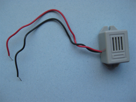
FIGURE 12-10: This noisy little buzzer is simple to operate.
When shopping for a buzzer, you should consider three specifications:
- The frequency of sound it emits: Most buzzers give off sound at one frequency, somewhere in the range of 2 kHz to 4 kHz.
- The operating voltage and voltage range: Make sure you get a buzzer that works with the DC voltage that your project supplies.
- The level of sound it produces in unit of decibels (dB): The higher the decibel rating, the louder (and more obnoxious) the sound emitted. Higher DC voltage provides a higher sound level.
Be careful that the sound doesn’t get so loud that it damages your hearing. You can suffer permanent hearing loss if exposed to sound at 90 dB or higher for a sustained interval — but you won’t feel pain until sound reaches at least 125 dB.
Creating good vibrations with DC motors
Have you ever wondered what causes your smartphone to vibrate? No, it’s not Mexican jumping beans: These devices normally use a DC motor, which changes electrical energy (such as the energy stored in a battery) into motion. That motion may involve turning the wheels of a robot that you built or shaking your smartphone. In fact, you can use a DC motor in any project in which you need motion.
Electromagnets make up an important part of DC motors because these motors consist of, essentially, an electromagnet on an axle rotating between two permanent magnets, as you can see in Figure 12-11.

FIGURE 12-11: How the parts of a simple DC motor fit together.
The positive and negative terminals of the battery connect so that each end of the electromagnet has the same polarity as the permanent magnet next to it. Like poles of magnets repel each other. This repelling action moves the electromagnet and causes the axle to spin. As the axle spins, the positive and negative connections to the electromagnet swap places, so the magnets continue to push the axle around.
A simple mechanism — consisting of a commutator (a segmented wheel with each segment connected to a different end of the electromagnet) and brushes that touch the commutator — causes the connections to change. The commutator turns with the axle and the brushes are stationary, with one brush connected to the positive battery terminal and the other brush to the negative battery terminal. As the axle — and (therefore) the commutator — rotates, the segment in contact with each brush changes. This, in turn, changes which end of the electromagnet is connected to negative or positive voltage.
If you want to get a feel for the mechanism inside a DC motor, buy a cheap one for a few dollars and tear it apart.
The axle in a DC motor rotates a few thousand times per minute — a bit fast for most applications. Suppliers sell DC motors with something called a gear head premounted; this device reduces the speed of the output shaft to under a hundred revolutions per minute (rpm). This technique is similar to the way that changing gears in your car changes the speed of the car.
Suppliers’ catalogs typically list several specifications for the motors they carry. When you shop for electric motors, consider these two key characteristics:
- Speed: The speed (in rpm) that you need depends on your project. For example, when turning the wheels of a model car, you may aim for 60 rpm, with the motor rotating the wheels once per second.
- Operating voltage: The operating voltage is given as a range. Hobby electronics projects typically use a motor that works in the 4.5 V to 12 V range. Also note the manufacturer’s nominal voltage and stated rpm for the motor. The motor runs at this rpm when you supply the nominal voltage. If you supply less than the nominal voltage, the motor runs slower than the stated rpm. If you supply more, it may run faster but it’ll probably burn out.
DC motors have two wires (or terminals that you solder wires to), one each for the positive and negative supply voltage. You run the motor by simply supplying a DC voltage that generates the speed that you want, and you switch off the voltage when you want the motor to stop. For many DC motors, changing the polarity of the supply voltage changes the direction of the axle rotation.
You can use a more efficient method of controlling the speed of the motor called pulse-width modulation. This method turns voltage on and off in quick pulses. The longer the on intervals, the faster the motor goes. If you’re building a kit for something motor controlled (such as a robot), this type of speed control should be included with the electronics for the kit.
If you’re attaching things such as wheels, fan blades, and so on to the motor shaft, make sure that you've attached the component securely before you apply power to the motor. If you don't, the item may spin off and hit you, or someone near and dear to you, in the face.