
Chapter 3
Running Around in Circuits
IN THIS CHAPTER
![]() Making the right connections with a circuit
Making the right connections with a circuit
![]() Being positive about the direction of current flow
Being positive about the direction of current flow
![]() Shedding light on a circuit in action
Shedding light on a circuit in action
![]() Seeing how voltages and currents measure up
Seeing how voltages and currents measure up
![]() Finding out how much electrical energy is used
Finding out how much electrical energy is used
Electric current doesn’t flow just anywhere. (If it did, you’d be getting shocked all the time.) Electrons only flow if you provide a closed conductive path, known as an electrical circuit, or simply a circuit, for them to move through, and initiate the flow with a battery or other source of electrical energy.
In this chapter, you discover how electric current flows through a circuit and why conventional current can be thought of as electrons moving in reverse. You also explore the depths of a simple electronic circuit that you can build yourself. Finally, you find out how to measure voltages and currents in that circuit and how to figure out the amount of power supplied and used in a circuit.
Comparing Closed, Open, and Short Circuits
You need a closed path, or closed circuit, to get electric current to flow. If there’s a break anywhere in the path, you have an open circuit, and the current stops flowing — and the metal atoms in the wire quickly settle down to a peaceful, electrically neutral existence. (See Figure 3-1.)
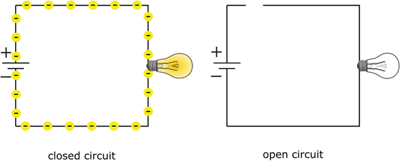
FIGURE 3-1: A closed circuit allows current to flow, but an open circuit leaves electrons stranded.
Picture a gallon of water flowing through an open pipe. The water will flow for a short time but then stop when all the water exits the pipe. If you pump water through a closed pipe system, the water will continue to flow as long as you keep forcing it to move.
Open circuits are often created by design. For instance, a simple light switch opens and closes the circuit that connects a light to a power source. When you build a circuit, it’s a good idea to disconnect the battery or other power source when the circuit is not in use. Technically, that’s creating an open circuit.
A flashlight that is off is an open circuit. In the flashlight in Figure 3-2, the flat black button in the lower left controls the switch inside. The switch is nothing more than two flexible pieces of metal in close proximity to each other. With the black button slid all the way to the right, the switch is in an open position and the flashlight is off.
Turning the flashlight on by sliding the black button to the left pushes the two pieces of metal together — or closes the switch — and completes the circuit so that current can flow. (See Figure 3-3.)
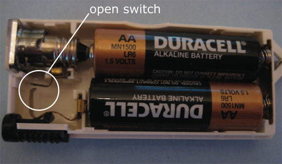
FIGURE 3-2: A switch in the open position disconnects the light bulb from the battery, creating an open circuit.
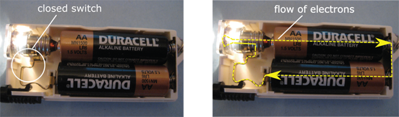
FIGURE 3-3: Closing the switch completes the conductive path in this flashlight, allowing electrons to flow.
Sometimes open circuits are created by accident. You forget to connect a battery, for instance, or there’s a break in a wire somewhere in your circuit. When you build a circuit using a solderless breadboard (which I discuss in Chapters 2 and 15), you may mistakenly plug one side of a component into the wrong hole in the breadboard, leaving that component unconnected and creating an open circuit. Accidental open circuits are usually harmless but can be the source of much frustration when you’re trying to figure out why your circuit isn’t working the way you think it should.
Short circuits are another matter entirely. A short circuit is a direct connection between two points in a circuit that aren’t supposed to be directly connected, such as the two terminals of a power supply. (See Figure 3-4.) As you discover in Chapter 5, electric current takes the path of least resistance, so in a short circuit, the current will bypass other parallel paths and travel through the direct connection. (Think of the current as being lazy and taking the path through which it doesn’t have to do much work.)
 If you short out a power supply, you send large amounts of electrical energy from one side of the power supply to the other. With nothing in the circuit to limit the current and absorb the electrical energy, heat builds up quickly in the wire and in the power supply. A short circuit can melt the insulation around a wire and may cause a fire, an explosion, or a release of harmful chemicals from certain power supplies, such as a rechargeable battery or a car battery.
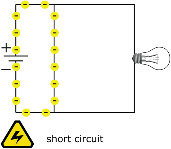
FIGURE 3-4: In a short circuit, current may be diverted from the path you intended it to flow through.
Understanding Conventional Current Flow
Early experimenters believed that electric current was the flow of positive charges, so they described electric current as the flow of a positive charge from a positive terminal to a negative terminal. Much later, experimenters discovered electrons and determined that they flow from a negative terminal to a positive terminal. That original convention is still with us today — so the standard is to depict the direction of electric current in diagrams with an arrow that points opposite the direction of actual electron flow.
 Conventional current is the flow of a positive charge from positive to negative and is the reverse of real electron flow. (See Figure 3-5.) All descriptions of electronic circuits use conventional current, so if you see an arrow depicting current flow in a circuit diagram, you know it is showing the direction of conventional current flow. In electronics, the symbol I represents conventional current, measured in amperes (or amps, abbreviated A). You’re more likely to encounter milliamps (mA) in circuits you build at home. A milliamp is one one-thousandth of an amp.
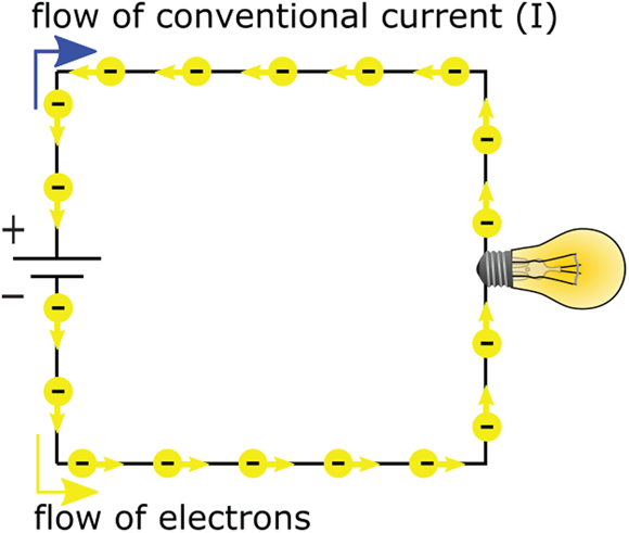
FIGURE 3-5: Conventional current flows one way; electrons flow the other way.
 In AC circuits, current is constantly reversing direction. So how do you show current flow in a circuit diagram? Which way should the arrow point? The answer is that it doesn’t matter. You arbitrarily choose a direction for the current flow (known as the reference direction), and you label that current I. The value of I fluctuates up and down as the current alternates. If the value of I is negative, that just means that the (conventional) current is flowing in the direction opposite to the way the arrow is pointing.
Examining a Basic Circuit
The diagram in Figure 3-6 depicts a battery-operated circuit that powers a light-emitting diode (LED), much like what you might find in a mini LED flashlight. What you see in the figure is a circuit diagram, or schematic, that shows all the components of the circuit and how they are connected. (I discuss schematics in detail in Chapter 14.)
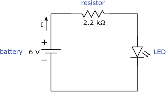
FIGURE 3-6: Current delivers electrical energy from the battery to the resistor and the LED.
The battery is supplying 6 volts DC (that is, a steady 6 volts) to the circuit. The plus sign near the battery symbol indicates the positive terminal of the battery, from which current flows (conventional current, of course). The negative sign near the battery symbol indicates the negative terminal of the battery, to which the current flows after it makes its way around the circuit. The arrow in the circuit indicates the reference direction of current flow, and because it’s pointing away from the positive terminal of the battery in a DC circuit, you should expect the value of the current to be positive all the time.
The lines in the circuit diagram show how the circuit components are connected, using wire or other connectors. (I discuss various kinds of wire and connectors in Chapter 12.) Electronic components are usually made with leads — protruding wires connected to the innards of the component that provide the means to connect the component to other circuit elements.
The zigzag symbol in the circuit diagram represents a resistor. The role of the resistor is to limit the amount of current that flows through the circuit, much like a kink in a garden hose restricts water flow. Chapter 5 gives you more information about resistors, but for now, just know that resistance is measured in units called ohms (symbolized as Ω) and that the resistor in this circuit is keeping the LED from being destroyed.
The LED is symbolized by a triangle with a line segment on one end and two arrows pointing outward. The triangular part of the symbol represents a diode, and the two arrows facing out represent the fact that this diode emits light (hence, it is a light-emitting diode). Diodes are part of a special class of electronic component known as semiconductors, which I describe in Chapter 9.
By building this circuit and taking some measurements of voltages and current, you can learn a lot about how circuits work. And voltage and current measurements are the key to finding out how the electrical energy generated by the battery is used in the circuit. So let’s get started!
Building the basic LED circuit
Here are the parts you need to construct the LED circuit:
- Four 1.5-volt AA batteries (make sure they’re fresh)
- One four-battery holder (for AA batteries)
- One battery clip
- One 2.2 kΩ resistor (identified by a red-red-red stripe pattern and then a gold or silver stripe)
- One red LED (any size)
- Three insulated alligator clips or one solderless breadboard
You can find out where to get parts in Chapter 2 or Chapter 19.
Insert the batteries into the battery holder, observing the polarity markers, and attach the battery clip. The battery holder is wired to connect the four batteries end-to-end, creating a battery pack that supplies ![]() volts via the wires extending from the clip.
volts via the wires extending from the clip.
Before you build the circuit, you may want to use your multimeter to verify the voltage of your battery pack and the value of your resistor (especially if you're not sure of their values). For details on using a multimeter, see Chapter 16.
Set your multimeter to measure DC voltage, hold the black (negative) multimeter probe to the black lead coming out of the battery pack, and hold the red (positive) multimeter probe to the red lead coming out of the battery pack. You should get a reading of at least 6 volts, because fresh batteries supply a higher voltage than their rating. If the reading is much less than 6 volts, remove the batteries and check each one individually.
To check the resistor value, switch your multimeter selector to measure ohms, and touch one multimeter lead to each side of the resistor (it doesn’t matter which way). Verify that the resistor value is roughly 2.2 kΩ (which is 2,200 Ω).
You can build the LED circuit by using alligator clips to connect the components or by using a solderless breadboard to make the connections. I walk you through both construction methods. Note that when I discuss taking voltage and current measurements, I provide pictures showing the breadboard circuit. You can read more about constructing circuits in Chapter 15.
Building the circuit with alligator clips
Use the alligator clips to make connections in the circuit, as shown in Figure 3-7. Note that the orientation of the resistor doesn’t matter, but the orientation of the LED does matter. You connect the longer lead of the LED to the resistor, and the shorter lead of the LED to the negative side (black wire) of your battery pack. When you make your final connection, the LED should glow.
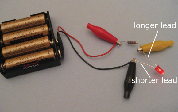
FIGURE 3-7: Alligator clips connect components in this simple LED circuit.
If you connect an LED the wrong way, it won’t light and it might become damaged. You find out why in Chapter 9.
Building the circuit with a solderless breadboard
Figures 3-8 and 3-9 show the circuit set up on a solderless breadboard. You find out in Chapters 2 and 15 that a solderless breadboard makes connections between holes so that all you have to do is insert components in the right places. On the left and right sides of the breadboard, all the holes in each column are connected to each other. In each of the two center sections of the breadboard, the five holes in each row are all connected to each other.
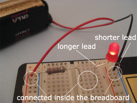
FIGURE 3-8: The LED circuit is easy to set up on a solderless breadboard.
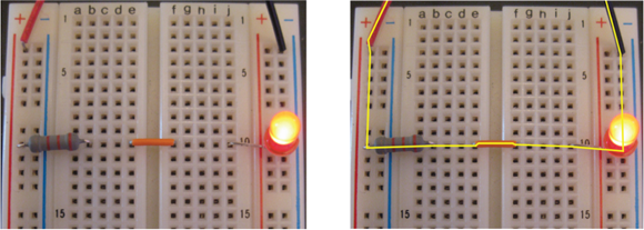
FIGURE 3-9: A neater way to build your circuit. The yellow line shows the path through which current flows to and from the battery pack.
As you set up the circuit on the breadboard, remember that it doesn’t matter how you orient the resistor, but be sure to orient the LED so that the shorter lead is connected to the negative side of the battery pack. If you clip the leads to make your circuit neater (as shown in Figure 3-9), remember to keep track of which lead was shorter to begin with. You use a short jumper wire in your trimmed circuit to connect the resistor to the LED. (In Chapter 9, you find out another way to identify which lead is which on an LED.)
Examining voltages
In this section, I explain how to use your multimeter to measure the voltage across the battery pack, the resistor, and the LED in your circuit. (You find detailed information about how to use a multimeter in Chapter 16.)
Note that the connection points between components are the same whether you built the circuit using a breadboard or alligator clips. The red lead of your multimeter should be at a higher voltage than the black lead, so take care to orient the probes as described. Set your multimeter to measure DC voltage and get ready to take some measurements!
First, measure the voltage supplied to the circuit by the battery pack. Connect the positive (red) multimeter lead to the point where the positive (red lead) side of the battery pack connects to the resistor, and the negative (black) multimeter lead to the point where the negative (black lead) side of the battery pack connects to the LED. See Figure 3-10. Do you get a voltage reading that is close to the nominal supply voltage of 6 V? (Fresh batteries may supply more than 6 V; old batteries usually supply less than 6 V.)
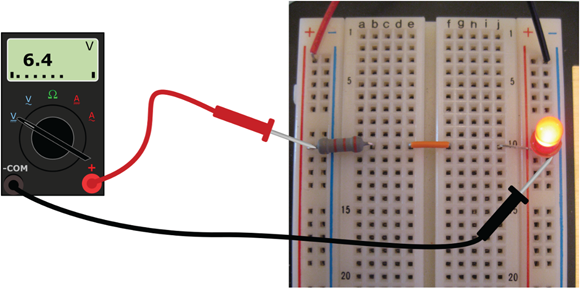
FIGURE 3-10: Measure the voltage supplied by the battery pack.
Next, measure the voltage across the resistor. Connect the positive (red) multimeter lead to the point where the resistor connects with the positive side of the battery pack, and the negative (black) multimeter lead to the other side of the resistor. See Figure 3-11. Your voltage reading should be close to the one that appears on the multimeter in the figure.
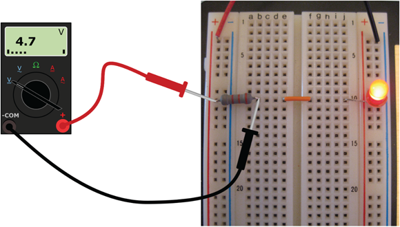
FIGURE 3-11: Measure the voltage across the resistor.
Finally, measure the voltage across the LED. Place the red multimeter lead to the point where the LED connects with the resistor, and the black multimeter lead to the point where the LED connects to the negative side of the battery pack. See Figure 3-12. Was your voltage reading close to the one in the figure?
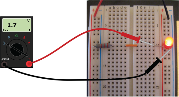
FIGURE 3-12: Measure the voltage across the LED.
My measurements show that in my circuit, the battery pack is supplying 6.4 volts, and that 4.7 volts are dropped across the resistor and 1.7 volts are dropped across the LED. It’s not a coincidence that the sum of the voltage drops across the resistor and the LED is equal to the voltage supplied by the battery pack:
A give-and-take relationship is going on in this circuit: Voltage is the push the battery gives to get current moving, and energy from that push is absorbed when current moves through the resistor and the LED. As current flows through the resistor and the LED, voltage drops across each of those components. The resistor and the LED are using up energy supplied by the force (voltage) that pushes the current through them.
You can rearrange the preceding voltage equation to show that the resistor and the LED are dropping voltage as they use up the energy supplied by the battery:
When you drop voltage across a resistor, an LED, or another component, the voltage is more positive at the point where the current enters the component than it is at the point where the current exits the component. Voltage is a relative measurement because it’s the force that results from a difference in charge from one point to another. The voltage supplied by a battery represents the difference in charge from the positive terminal to the negative terminal, and that difference in charge has the potential to move current through a circuit; the circuit, in turn, absorbs the energy generated by that force as the current flows, which drops the voltage. No wonder voltage is sometimes called voltage drop, potential difference, or potential drop.
The important thing to note here is that as you travel around a DC circuit, you gain voltage going from the negative terminal of the battery to the positive terminal (that’s known as a voltage rise), and you lose, or drop, voltage as you continue in the same direction across circuit components. (See Figure 3-13.) By the time you get back to the negative terminal of the battery, all the battery voltage has been dropped and you’re back to 0 volts.
 With all circuits (whether AC or DC), if you start at any point in the circuit, and add the voltage rises and drops going around the circuit, you get zero volts. In other words, the net sum of the voltage rises and drops in voltage around a circuit is zero. (This rule is known as Kirchhoff’s Voltage Law. Kirchhoff is pronounced “keer-cough.”)
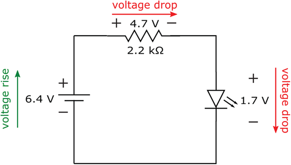
FIGURE 3-13: The voltage supplied by the battery is dropped across the resistor and the LED.
Keep in mind that these voltage drops have a physical meaning. The electrical energy supplied by the battery is absorbed by the resistor and the LED. The battery will keep supplying electrical energy, and the resistor and LED will keep absorbing that energy, until the battery dies (runs out of energy). That happens when all the chemicals inside the battery have been consumed in the chemical reactions that produced the positive and negative charges. In effect, all the chemical energy supplied by the battery has been converted into electrical energy — and absorbed by the circuit.
One of the fundamental laws of physics is that energy cannot be created or destroyed; it can only change form. You witness this law in action with the simple battery-driven LED circuit: Chemical energy is converted to electrical energy, which is converted to heat and light energy, which — well, you get the idea.
Measuring current
To measure the current running through your LED circuit, you must pass the current through your multimeter. The only way to do this is to interrupt the circuit between two components and insert your multimeter, as if it’s a circuit component, to complete the circuit.
Switch the multimeter selector to measure DC current in milliamps (mA). Then break the connection between the resistor and LED. (If you are using alligator clips, simply remove the clip that connects the resistor and the LED. If you are using a breadboard, remove the jumper wire.) The LED should turn off.
Next, touch the positive (red) multimeter lead to the unconnected resistor lead and the negative (black) multimeter lead to the unconnected LED lead, as shown in Figure 3-14. The LED should turn on, because the multimeter has completed the circuit, allowing current to run through it. The current reading I got was 2.14 mA.

FIGURE 3-14: To measure current, insert your multimeter into the path through which current flows.
Now, insert your multimeter at another connection point in the circuit (for instance, between the positive battery lead and the resistor), taking care to open the circuit at the point of measurement and to orient the multimeter leads with the positive lead at a more positive voltage point than the negative lead. Do you get the same current reading as before? You should, because this simple circuit provides only one path for current to flow.
Calculating power
The amount of energy consumed by an electronic component is known as power (abbreviated P), measured in watts (abbreviated W). Chapter 1 introduces you to this equation for calculating power:
where V represents voltage and I represents current. When you know the voltage dropped across a component and the current passing through the component, you can use the power equation to calculate the amount of energy consumed by each component.
For the resistor-LED circuit, you know the voltage drops (refer to Figure 3-13)and the current passing through the circuit (2.14 mA). Using this information, you can calculate the energy supplied or consumed by each component.
The energy consumed by the resistor is
where mW means milliwatts, or thousandths of a watt.
The energy consumed by the LED is
The energy supplied by the battery is
Note that the sum of the power consumed by the resistor and the LED (![]() ) is equal to the power supplied by the battery (13.7 mW). That’s because the battery is providing the electrical energy that the resistor and the LED are using. (Actually, the resistor is converting electrical energy to heat energy, and the LED is converting electrical energy into light energy.)
) is equal to the power supplied by the battery (13.7 mW). That’s because the battery is providing the electrical energy that the resistor and the LED are using. (Actually, the resistor is converting electrical energy to heat energy, and the LED is converting electrical energy into light energy.)
Say you substitute a 9-volt battery for the 6-volt battery pack. Now you supply more voltage to the circuit, so you can expect to push more current through it and deliver more energy to the resistor and the LED. Because the LED receives more electrical energy to convert into light energy, it will shine more brightly. (There are limits to how much voltage and current you can supply to an LED before it breaks down and no longer works. You find out more about this subject in Chapter 9.)