5
Setting Up Animation and Rigging
In Chapter 4, Adjusting Cameras and Lights, you saw why you should ignore certain concepts in Blender, specifically cameras and lights, because they don’t transfer easily to Godot. This chapter is sort of an opposite case. You might be wondering whether a game engine can’t move objects around for us, right? After all, we use a game engine to facilitate things such as displaying models, creating environments with visually rich effects, and so on. It’s normal to expect a game engine to take care of animating our models as well.
Although animating simple objects is perfectly possible in Godot, doing it for complex models such as a human character (or any bipeds, such as a robot) or a lion (or any quadrupeds, such as a cow) will take a lot of effort. Therefore, it makes much more sense to do most animations in Blender because it offers a much more streamlined workflow. We’ll explain in detail why that is so you can apply a similar reasoning process in your own projects.
Sometimes, you will have a model that looks nice and complete, but it won’t be suitable or ready to be animated. In Chapter 1, Creating Low-Poly Models, we discussed vertices, faces, and edges. We will revisit some of those concepts in the context of getting our models ready for animation.
Then, when we believe the model is ready, we’ll look at Blender’s animation capabilities. We’ll do this by discovering two new things. First, we’ll utilize a new method called rigging and construct a rig that’s ubiquitous in animating models. Second, we’ll switch to a new workspace dedicated to animations. During this effort, you’ll get to know a whole different side of Blender.
After you see how rigging is done and how models can be animated, we’ll look into ways to prepare and store more animations in Blender so that they can easily be used later in Godot. So, once you know beforehand what will be required down the line, this knowledge might help you in setting things up accordingly in Blender before it’s too cumbersome to change later.
Despite the following section titles looking deceptively short, we have a lot to cover in this chapter:
- Where to build animations
- Understanding the readiness of models
- Creating animations
- Getting animations ready for Godot
In the end, you’ll know whether Blender or Godot is the right environment to tackle animations and how to get models ready for animations so that you can rig them.
Technical requirements
There will be a lot of moving parts, figuratively and literally, in this chapter. Animation and rigging are challenging topics for most people who start practicing 3D. Although we’ll take things step by step, to give you extra help along the way, you might want to use some of the files that are in the interim stages instead of doing it all at once.
As usual, the book’s repository will have the necessary files for this chapter at the following link: https://github.com/PacktPublishing/Game-Development-with-Blender-and-Godot.
Where to build animations
Both Blender and Godot Engine have animating capabilities. Therefore, you might be wondering which software is better for creating animations. To answer this crucial question, we should be discussing what we are animating. When it comes to animations, especially in game development, we will be tackling the following two main concepts:
- Whole-body objects: Objects such as a bouncing ball, a boat, or a projectile thrown from a source are all examples of objects that act like a solid system with no individually moving parts. The system can move as a whole without depending on its individual parts.
- Connected systems: Some systems depend on individual parts to be in motion. These systems have parts that are connected to each other and the individual parts work together to move the system they are part of. For example, cats use their feet, birds use their wings, and a human body moves in a certain direction using two appendages that are either in contact with a surface or interact with the medium they are in.
Sometimes, some tools and gadgets in real life can do a similar job, and it’s possible to use one over another for a quick solution. However, every so often, we would like to pick the best tool for the job. We’ll discuss both Blender and Godot in the context of the concepts we have just pointed out to see which option might be a better choice.
Animating in Godot Engine
Godot has a component, AnimationPlayer, that helps you build animations. We’ll look at it more closely in later chapters when we import our models to create a point-and-click adventure game. Similar to other applications’ animation components, it depends on setting keyframes to mark the changing points of an animated object. For example, to create a bouncing ball animation, you’d mark the ball sitting still on a plane in the earlier frames of the animation and mark a higher position in the world in the later frames.
This is quite easy to do with Godot. You just have to mark the important events as keyframes, and this operation is called keying or inserting a key. Thus, the engine figures out how the object should move in between the two keyframes. However, when the system is much more complicated than a simple ball, and it has moving parts, you’d be expected to select these separate parts to key them. This is not easy to do in Godot since the workflow is not constructed in a way to facilitate such complex operations in an easy manner. Consequently, it’s best to use Godot Engine when the system is relatively simple.
Animating in Blender
As was just mentioned, when you are animating an object with parts that are responsible for creating the overall motion, such as animating a human body by moving individual parts such as feet and hands, then doing this kind of work in Blender will be the right choice thanks to a method called rigging. Later, in the Creating animations section, we’ll explain what rigging is and discover how to construct a rig for our models.
For now, it should be enough to know that individually moving parts for an animated body will require rigging to expedite the animation process. This is where Blender shines because it offers tools and custom interfaces to help you along the way.
Besides the ease of creating an animation, let’s point out another reason why Blender is a better choice for animating complex systems. If you construct your animations in Godot, you can only use them in Godot. On the contrary, a Blender animation will act as a source of truth so you can share it with other applications.
Wrapping up
We’ll say one more thing about why Blender might be a better choice regardless of the complexity of creating animations. If you ever want to create a trailer for your game and you’ve gone through the trouble of creating accurate enough camera and light conditions similar to the ones you are going to employ in your game, then you can take a render of your scene, composed of many frames, which will utilize Blender’s animation system.
So, for simple objects that can be moved, utilize Godot Engine’s animation system. For systems that have individually moving parts, it’s better to do it in Blender. After all, Blender has dedicated tools to facilitate the creation of advanced animations. Now, let’s discuss when your models are ready to be animated.
Understanding the readiness of models
In Chapter 1, Creating Low-Poly Models, we started with primitive objects and altered their vertices, faces, and edges. During that process, we were concerned with how the model would look. As corny as it may sound, looks might be misleading sometimes. To be animated correctly, a model has to respect certain conventions other than how it looks. In other words, you’ve got to be sure whether your model is ready.
Topology and rigging
The readiness level of a model could be defined by the term topology, which sounds a bit technical. In layman’s terms, it’s the distribution and arrangement of the vertices, edges, and faces of a model that altogether mark how optimized the model is for animation.
Not all topologies are created equal. There are bad and good topologies. Let’s look at Figure 5.1 to get a better idea about what we mean by topology or distribution, particularly as being bad or good.
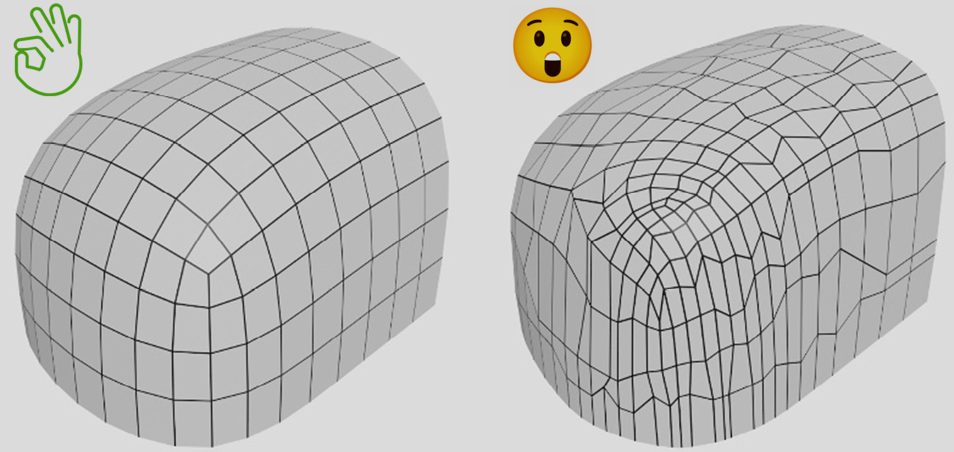
Figure 5.1 – The same model with two different distributions of vertices
The preceding figure shows a model with the same shape, but the topologies are different. Simply put, the left case is ready for animation, and the right one could use some work to straighten up those vertices to form a good flow. Then, you’d have to fix some of the irregularities by evenly distributing many of the faces that congregate. So, not only is the right case an eyesore, but it’s also detrimental during the animation process.
Let’s briefly touch on the role of rigging to understand the importance of good topology. If you were to model a human hand, you’d be designing fingers, knuckles, and the wrist. The model, or more correctly, its volume, would be hollow. In other words, you’d only be creating the vertices that would give the shape of a hand. However, in our minds, we know that this hand should have bones inside. When you wiggle your fingers around or bend your fingers at the knuckles and joints, different parts of the skeleton start moving so that the outer structure that’s connected to the bone system can move accordingly.
To simulate this, you take advantage of a practice called rigging, which involves introducing a skeleton system and a series of constraints that manage how the skeleton system behaves. We’ll work on a rigging example later in the chapter. For now, we are still concerned about our models being ready for the rigging to take place. To emphasize the relationship between topology and rigging better, let’s turn our attention to Figure 5.2.
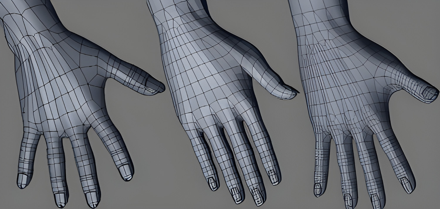
Figure 5.2 – Different topologies for a hand model
Observe how the faces are aligned more naturally in the middle case, which certainly looks like an improvement over the left one. Then, still for the middle case, look where the big thumb meets the main part of the hand; that area could use a bit more detail so that when the thumb stretches out like in the right case, there would be enough geometry to accommodate the skeleton’s behavior. Compare the first and the third hands to see which one looks more natural to your eye when it comes to flesh and skin in between fingers.
When a model is bending or stretching at certain points, it will be creating some creased and protruded areas, similar to where the fingers meet the hand in the preceding figure. If vertices, hence faces, don’t have a smooth flow, the model will look ripped or crushed in these weak spots. Having the correct topology is a topic that’s hard to master and it throws off a lot of beginners when they want to get into animation and rigging. You can find a few links that can help you understand the difference between a good and bad topology in the Further reading section.
To satisfy a good topology, since it’s necessary to line up edges and faces correctly where the action will occur, we need a mechanism to move problematic edges and faces around so that they will be in the right place. For this, we are going to discover a new method, or rather, a shortcut.
Grabbing
In Chapter 1, Creating Low-Poly Models, you got to know two methods that are very commonly used among Blender fans. They were Rotate (R as a shortcut) and Scale (S as a shortcut). There is a third common method that we intentionally omitted during that exercise. We depended on modifiers that helped us move vertices around, so we got away without it; however, it’s now time to employ it.
If you are able to rotate and scale things, then why can’t you move things around? In fact, you can, and this new method will help you move vertices, edges, and faces anywhere you want. There is only one caveat. Although most people refer to this operation as Move, its shortcut is a bit bizarre; it’s G. So, an easier way to think of this shortcut in the context of moving might perhaps be grabbing. You grab a vertex and leave it somewhere, in a sense.
In most Blender tutorials, you may find people use grab and move interchangeably. They're one and the same. So, throughout this book, when you see the word move, we mean the grab operation and the G shortcut.
Let’s practice this new piece of knowledge with a series of simple steps. After you start a new file, perform the following steps:
- Press Tab to enter Edit Mode.
- Select only one vertex of the default cube.
- Press G and move your mouse around.
The vertex you selected is now being pulled around while you are moving your mouse. To terminate the grabbing, you can click anywhere and this should rest the selected vertex at its last position. Figure 5.3 is an example of what we want to achieve.
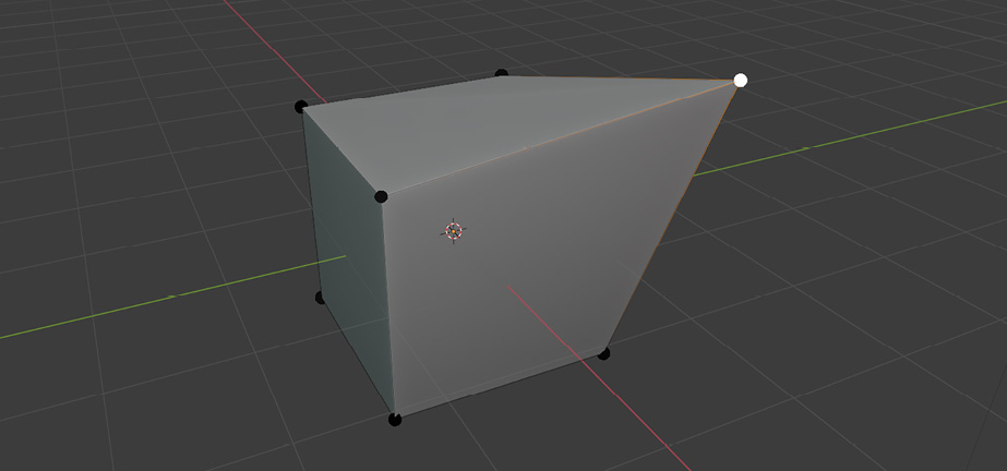
Figure 5.3 – A vertex grabbed out of its original place and moved somewhere else
You might have surmised that the vertex was moving freely in all three axes, and that would be correct. If you want to limit the movement to a certain axis, and if you wish to move the vertex a precise amount, you can do that too. While still in Edit Mode, perform the following steps:
- Select another vertex.
- Press G, then X.
- Type 0.5.
You can pick any one of the other two axes if you want. Regardless, the value you type for any given axis defines the movement amount. So, a negative value will still move the selected part in the axis you choose, just in the opposite direction.
Additionally, sometimes you might want to move the selection in any but a certain direction. When you initiate a grab shortcut, if you press Shift before you pick the axis, it’ll move the selection to the other two remaining axes. So, Shift+X would move things anywhere but on the X axis.
Practice the grabbing operation a bit more by selecting edges or faces if you would like. Soon, we’ll explore the building blocks of animation. During that effort, you’ll most likely utilize the grab operation. So, when you are ready, let’s see how we can animate things.
Creating animations
As we mentioned in the Where to build animations section, the type of animation we’ll do in Blender involves having individual parts of a system that move independently from each other or collaboratively move together sometimes. We also said that we would need a method called rigging, so let’s give an example to understand why rigging is useful.
When you talk, whether you are sitting or walking, the muscles and bones that are responsible for the talking are generally not affected by or affecting the other parts of your body. However, when you are walking, your legs rotate around the hip bones, and the rest of the system triggers other natural actions, such as swinging your arms, moving your shoulders slightly forward and backward, and so on.
In both cases where you have a local or system-wide dependency, we eventually move some of the vertices that make up a model. Since moving so many vertices is a lot of work, we use a structure we place inside the model to tell the necessary vertices where to move. The process to create such a structure is called rigging. In a way, rigging mimics what bones and muscles do in real life.
In this section, we’ll work on a simple rigging process and rig a low-poly snake. Through this process, you’ll prepare the model for animation, but first, we'll get to know some of the essential components, as follows:
- Armature: An armature, in simple terms, is a set of bones, but a better definition might be a framework serving as a control structure – what materials are to textures, armatures are to bones. So, the same armature could have multiple bones. Furthermore, the rigging process could involve many armatures if the system that’s animated requires so.
- Bone: This is the most essential part of a rigging system. Without bones, there would not be armatures, therefore nothing to animate. In real life, when your bones move outside of their zone of freedom, you feel pain, so your body keeps things intact. There are similar ways to restrict a bone’s freedom digitally, so to speak, so it works in tandem with other bones.
We’ll first look at how to rig a model. For this effort, we’ll utilize one armature and many bones. After adding constraints to some of the bones, the rigging process will be complete. So, in the end, we will use our rig to animate the snake.
Rigging
Now that the theoretical stuff is out of the way, we can focus on the practical aspects, mainly how to set up armatures and bones. To focus on the rigging process, we’ll use a low-poly snake model. The Snake.blend file in Chapter 5’s Start folder is a good starting point, and by the end of this Rigging section, you’ll have reached what you see in the Snake.Rigged.blend file.
Besides these two files, we’ll mention other complementary files that show the interim phase. As always, you can find all of these files at the URL mentioned in the Technical requirements section.
After you open the Snake.blend file, let’s add an armature by performing the following steps:
- Press 3 on your numpad to switch to the Right Orthographic view.
- Press Shift+A.
- Select Armature.
You can also find the result of the preceding operations in the Snake.First Bone.blend file. If your keyboard doesn’t have a numpad, then you can click on the X axis in the gizmo in the top-right corner of 3D Viewport until you read Right Orthographic in the top-left corner. The following figure should help you see what we have done so far:

Figure 5.4 – Beware the snake! On second thought, it doesn’t seem to have a mean bone in its body
We now have a new object type in our scene: an armature. You can see it in Outliner too with two green stick figures next to its title. Right now, we have one bone in the armature. So, bone and armature kind of mean the same thing at this point. Our goal, in rigging, will be to create and distribute a bunch of bones inside the snake’s mesh. So, let’s add more.
We seem to have a problem, though. That bone we added earlier looks like it’s occluded by the snake’s tail. So, if we keep adding more bones and laying them out so that they align with the snake’s body, we won’t be able to see what we are doing. Luckily, the solution is a couple of clicks away. While the armature is still selected, you can expand Viewport Display in the Armature settings in the Properties panel and turn on the In Front option. This will make sure the armature is always visible.
Missing out on a numpad
Numpad shortcuts are helpful and they will make your life easier, especially during modeling and rigging when you need to view your work from certain angles often on. The following website offers eight different ways to mimic a numpad: https://essentialpicks.com/using-blender-with-no-numpad/.
Meshes are composed of vertices, faces, and edges. Similarly, bones are made of three components: root, body, and tip. The tip can be the root of another bone and vice versa. Just as we can go into Edit Mode for a mesh to change its inner parts, we can do so with an armature. So, select the armature and press Tab.
You should be able to click on and select the root and tip separately. When you select the structure in between the joints, it’ll automatically select the root and the tip since it’s all connected. Figure 5.5 shows only the tip selected.

Figure 5.5 – The tip of the bone is selected in Edit Mode
Credit where credit is due
The snake model we are rigging in this section is an asset created by an artist known as Quaternius. You can follow his work at https://quaternius.com. We’ll be using his other assets in later chapters as well. So, thank you for your generosity.
Now, we are ready to add more bones to the armature. We’ll do that by first positioning that initial bone, then we’ll add new bones coming off the tip. While still in Edit Mode, perform the following steps:
- Select the root joint.
- Press G and move the mouse so that the joint is somewhere in the middle of the snake’s chest.
- Click to finish grabbing.
- Select the tip joint.
- Press G and move the mouse so that the joint is somewhere near the Y axis but inside the tail.
- Click to finish grabbing again.
A figure might be extremely helpful since all of this moving and positioning sounds a bit arbitrary. Figure 5.6 is an example of what we have achieved in the last few steps.
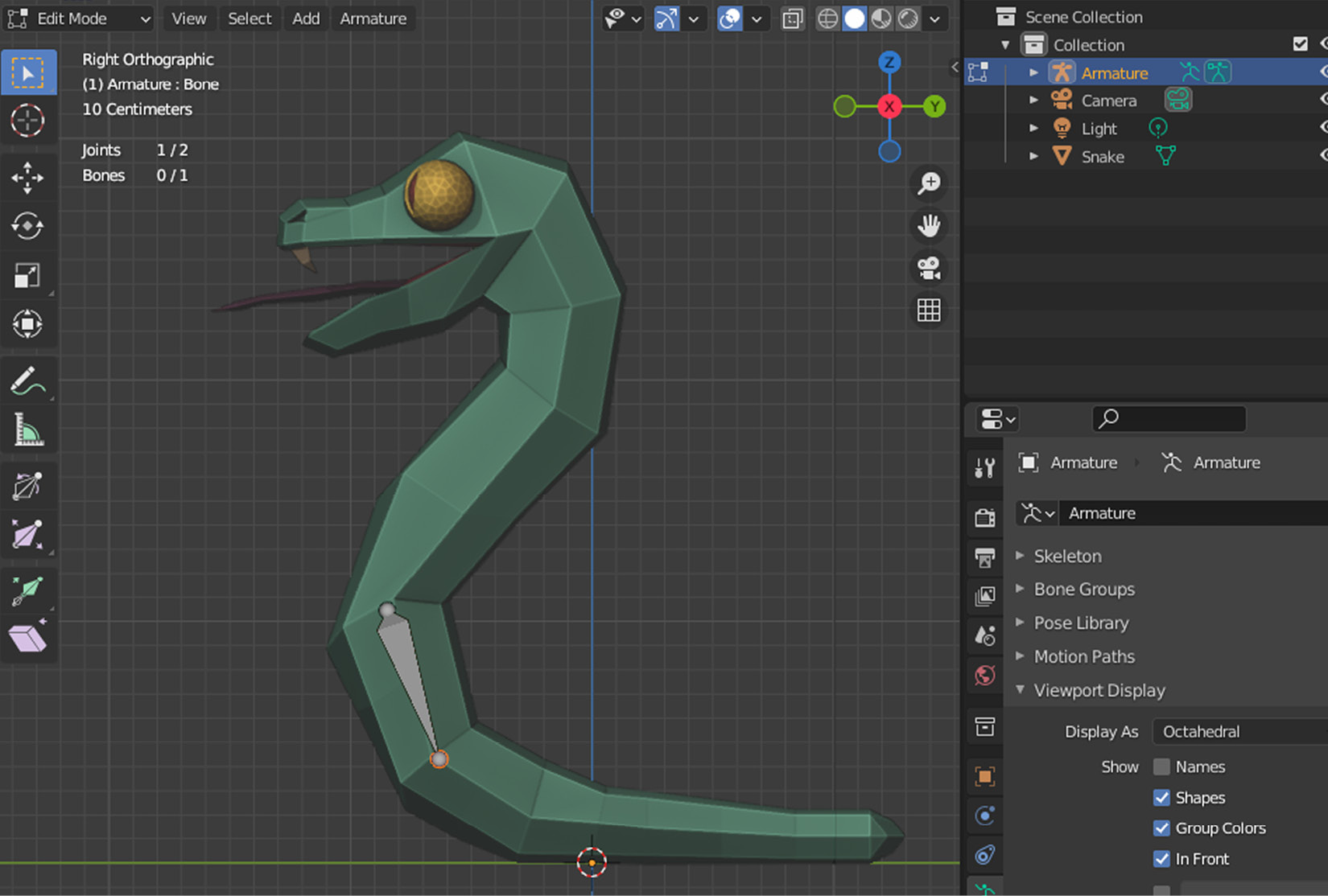
Figure 5.6 – A well-placed bone for our snake
Since up, down, or right concepts lose their meanings in the 3D space, it’s important to have a simple yet effective way to represent the natural flow of bones. If you compare Figure 5.5 and Figure 5.6, which correspond to the Snake.First Bone.Editing.blend and Snake.First Bone.Position.blend files, respectively, you’ll notice that the structure between the joints is going in different directions. The broader part of the bone is closer to the root, and the narrower end of the bone is approaching its tip. For example, imagine your kneecap as the root and your ankle as the tip of one bone. Moreover, hip bone to kneecap, elbow to wrist, and so on.
We have to add a few more bones to our system. We’ll do that by extruding the original bone. While still having the tip of the bone selected, perform the following steps:
- Press E to start extrusion.
- Move the mouse in the right and bottom direction so it follows the tail’s form.
- Click to finish extrusion.
- Repeat Steps 1 to 3 until you have four bones of roughly the same length.
The result is shown in Figure 5.7, and you can also open the Snake.Tail Bones.blend file to compare your result.
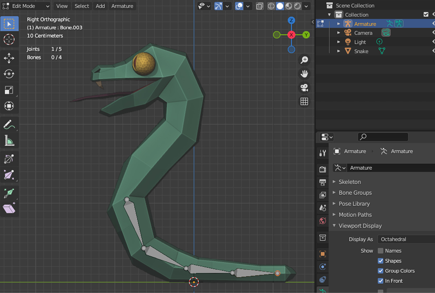
Figure 5.7 – Four bones that make up the tail
Importance of clicks
Similar to finishing a grabbing operation, extrusion needs a final click to solidify the position of an extruded object. Hence, throughout the rest of this chapter, when you follow a step where you see the word extrude, you are expected to click and finalize the extrusion when you are happy with the object’s position. If you prematurely terminate the extrusion, you can always hit G and grab this new object to move elsewhere and continue extruding if you wish. Thus, click to finalize both grabbing and extrusion, and use these two handy methods as often as you need. Also, if you change your mind while extruding, right-clicking will cancel this operation.
Extrusion helped us do a few things at once. We have created a new bone, positioned it correctly so its root aligned with the previous bone’s tip, parented this new bone to the previous bone, and finally, moved its tip to where we’d start the next bone.
We’re halfway through adding bones to the snake. That being said, now is a good time for a bit of housekeeping. We’ll be referencing some of these bones later, so it would be prudent of us to rename them now. If you have been paying attention to the new bones’ names after the extrusion, you must have seen that they are labeled in a format that goes like Bone.00X where X is the succeeding bone’s number. To rename all of the bones you have added so far, perform the following steps:
- Select the original bone.
- Press F2 and rename it to Tail.1.
- Repeat the preceding two steps for the rest of the bones so that their names look like Tail.X.
Let’s move on to adding bones for the torso. For this, we are going to utilize the original bone, which is now renamed Tail.1. Some of the decisions that you’ll make while rigging your models will depend on the situation you are going to use the rig for. It would have been perfectly possible to start the bones from the head and go all the way to the end of the tail. However, we know that this snake will have an inclination point, mainly where the torso and tail bones meet. Therefore, you need to perform the following steps:
- Select the root of Tail.1.
- Press E to extrude a new bone in the right and top direction, following the torso.
- Repeat Step 2 twice more so that you have three bones in the end.
- Select each new bone and rename them to look like Torso.X where X is a consecutive number starting at 1.
The result is what you see in Figure 5.8 and in the Snake.Torso Bones.blend file.
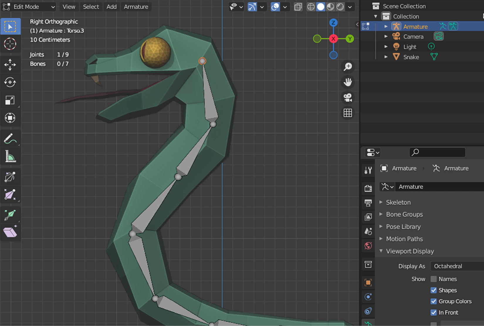
Figure 5.8 – New bones have been added following the torso to the head
We can now plan the remaining bones. We’ll be concerned with only two bones for brevity’s sake: the head and mouth bones. If you have been following all along, the tip of Torso.3 should still be selected. If not, select it, then perform the following steps:
- Press E to extrude a new bone to the end of the snake’s nose.
- Select Torso.3’s tip again.
- Press E to extrude a new bone to the end of the snake’s mouth.
In the end, the fully constructed skeleton, which you can find in the Snake.Full Skeleton.blend file, will look like what you see in Figure 5.9.
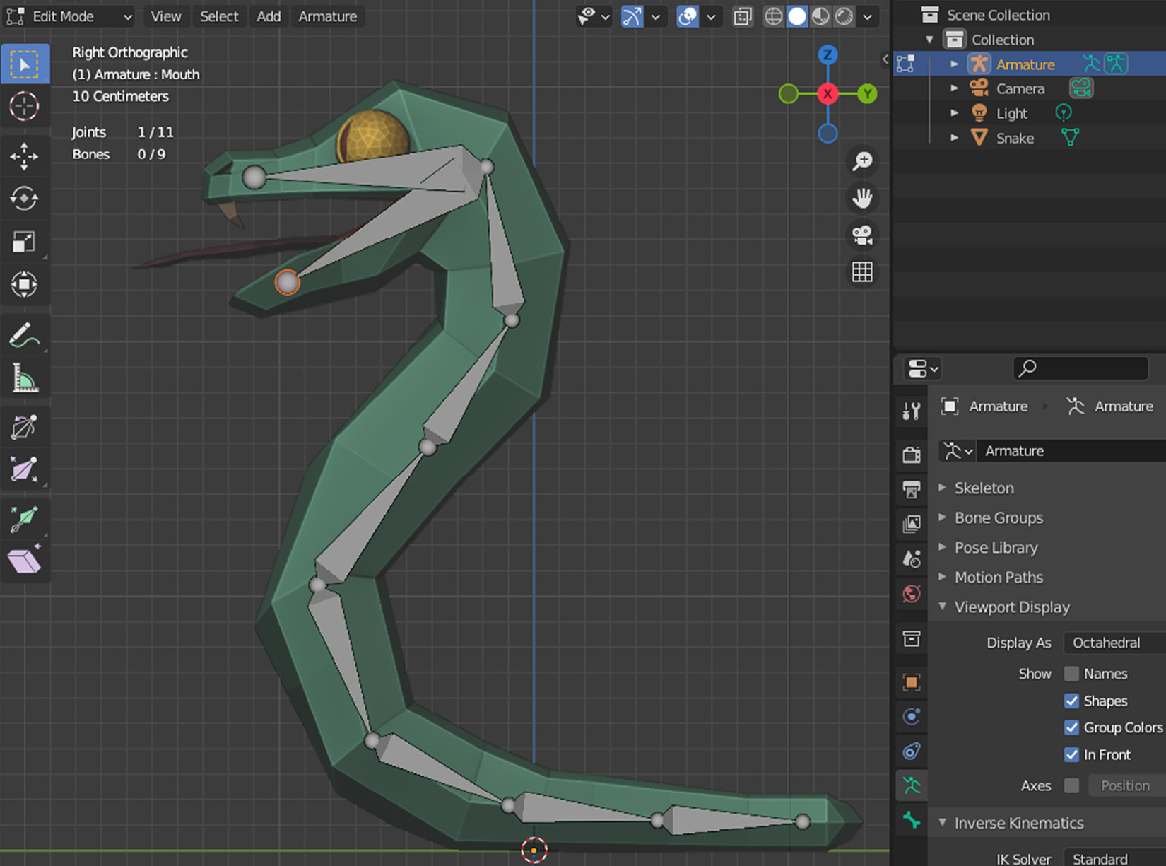
Figure 5.9 – The skeleton of our snake is complete
We are done with the skeleton. To complete the rigging, we need to add two more bones, which are usually called control bones. The following is an explanation of why a simple skeleton, although necessary, is still considered less than ideal. It has to do with the following two conflicting concepts:
- Forward Kinematics (FK): When you have a series of bones and you want to move the extremity bones, for example, a thumb in a human’s hand, the motion would have to be calculated while considering all of the position and orientation values for all of the interim bones starting from the shoulder joint. Thus, the motion starts off at the root and goes forward.
- Inverse Kinematics (IK): This is a much more efficient method where, following the preceding example, by moving a thumb, all of the connected bones determine their state in reverse order one at a time, instead of calculating the overall system’s behavior. Thus, the moving bone dictates how the bone behind should behave, and that bone behind does the same all the way to the root.
We prefer IK in our exercise since it’s much more convenient to use, and it is widely accepted in the industry. If you would like to get more in-depth information, especially on the math aspect of FK and IK, refer to the following two pages:
- https://www.sciencedirect.com/topics/engineering/forward-kinematics
- https://www.sciencedirect.com/topics/engineering/inverse-kinematics
To introduce IK to some of our bones, we need to create control bones that will propagate the motion to the rest of the bones. Although these control bones will look like they are part of the skeleton visually, they will be decoupled from the skeleton. Right now, all of the bones that have been extruded have been automatically parented. So, we’ll need to unparent our two control bones once we extrude them off the end bones.
It would seem one of these bones could be coming off the Head bone, and the other control bone, by symmetry, could be coming off the Tail.4 bone. Assuming you are still in the Right Orthographic view, in order to create these bones, you need to perform the following steps:
- Extrude a bone in the left direction off the tip of the Head bone.
- Rename this new bone as Head.IK.
- Extrude a bone in the right direction off the tip of the Tail.4 bone.
- Rename this new bone as Tail.IK.
We have created two new bones, but they are still attached to the skeleton. So, we need to separate them. ALT+P is a shortcut you can use to clear the parent relationship, but we’ll do the decoupling somewhere else since we’ll have to turn off another setting too. So, let’s do both at the same time, as follows:
- Select the Head.IK bone.
- Turn on the Bone Properties tab (the green bone icon) in the Properties panel.
- Expand the Relations section in that tab.
- Clear the parent by clicking on X in the name field.
- Turn off the Deform option.
- Repeat Steps 3 to 5 for the Tail.IK bone.
The Snake.Full Skeleton.IK.blend file contains all of the progress you have made so far, but let’s explain what we have done in the last several steps. We used to see the Armature properties, so we asked the Properties panel to show another view to display bone properties. We broke the connection of our control bones with their parent. Since there is no parent, the Connected checkbox automatically switched itself off. Lastly, we turned off a setting that’s the crux of all this whole operation: Deform.
If you recall what topology is and why we use a rigging system to animate systems that bend and stretch, then you’ll know that deformation is the key. We want the skeleton of the snake to deform the mesh it’s in. However, we wouldn’t want that for the control bones since we’ll use these to dictate the overall motion. So, they should not be deforming anything.
That being said, they will be responsible for IK, which is the last missing piece to the rigging. To complete the rigging, we need to add the IK ingredient, and we’ll do that in Pose Mode.
In Chapter 1, Creating Low-Poly Models, we went back and forth between Object Mode and Edit Mode. In this chapter, we’ve been in Edit Mode all this time to move the parts of a bone and extrude new ones. Bones can be in another mode, Pose Mode, with which you can define the relationship of the bones with each other by introducing constraints. Consider this new mode as editing the behavior of the armature, hence how the model will pose.
Assuming you are in Edit Mode already, press CTRL+Tab then press 2 to switch. Or, if you are in Object Mode, then CTRL+Tab will take you directly to Pose Mode. Keep in mind that this works if you have a bone or the armature selected. Alternatively, the dropdown in the top-left corner can help you to be in the right mode. We’re now ready to add IK constraints as follows:
- Select the Tail.4 bone.
- Turn on the Bone Constraints Properties tab (the blue bone icon with a strap around it) in the Properties panel.
- Choose the Inverse Kinematics option in the Add Bone Constraint dropdown.
- Repeat Step 3 for the Head bone.
We have added the missing IK component to two bones. Maybe you noticed that the constraint was not added to the control bones but to the bones just before them. We’ll now map some of the IK constraints' values to use the control bones. To do that, while the Head bone is selected, perform the following steps:
- Click on the square icon in the Target field of the IK constraint.
- Select Armature in the options.
- Click on the bone icon in the Bone field of the IK constraint.
- Select Head.IK in the options.
This will designate Head.IK as the control bone for the Head bone. So, from now on, whenever you interact with Head.IK, it will control the Head bone that is connected to the other bones all the way to the root. That’s why you see a dotted yellow line going from the tip to the joint in between the Torso.1 and Tail.1 bones.
Let’s associate Tail.4 and Tail.IK by following the preceding recipe so that interacting with Tail.IK can dictate the tail bones’ behavior. Select Tail.4 then perform the following steps:
- Select Armature in the options after clicking on the square icon in the Target field.
- Select Tail.IK in the options after clicking on the bone icon in the Bone field.
- Change the Chain Length value to 3.
The first two steps in the preceding set of instructions are pretty much exactly the same except that we picked the appropriate bone. The last step introduced a new concept that tells the control bone how far down the chain of bones the root bone is. The dotted line moved accordingly. The final result is what you see in Figure 5.10.
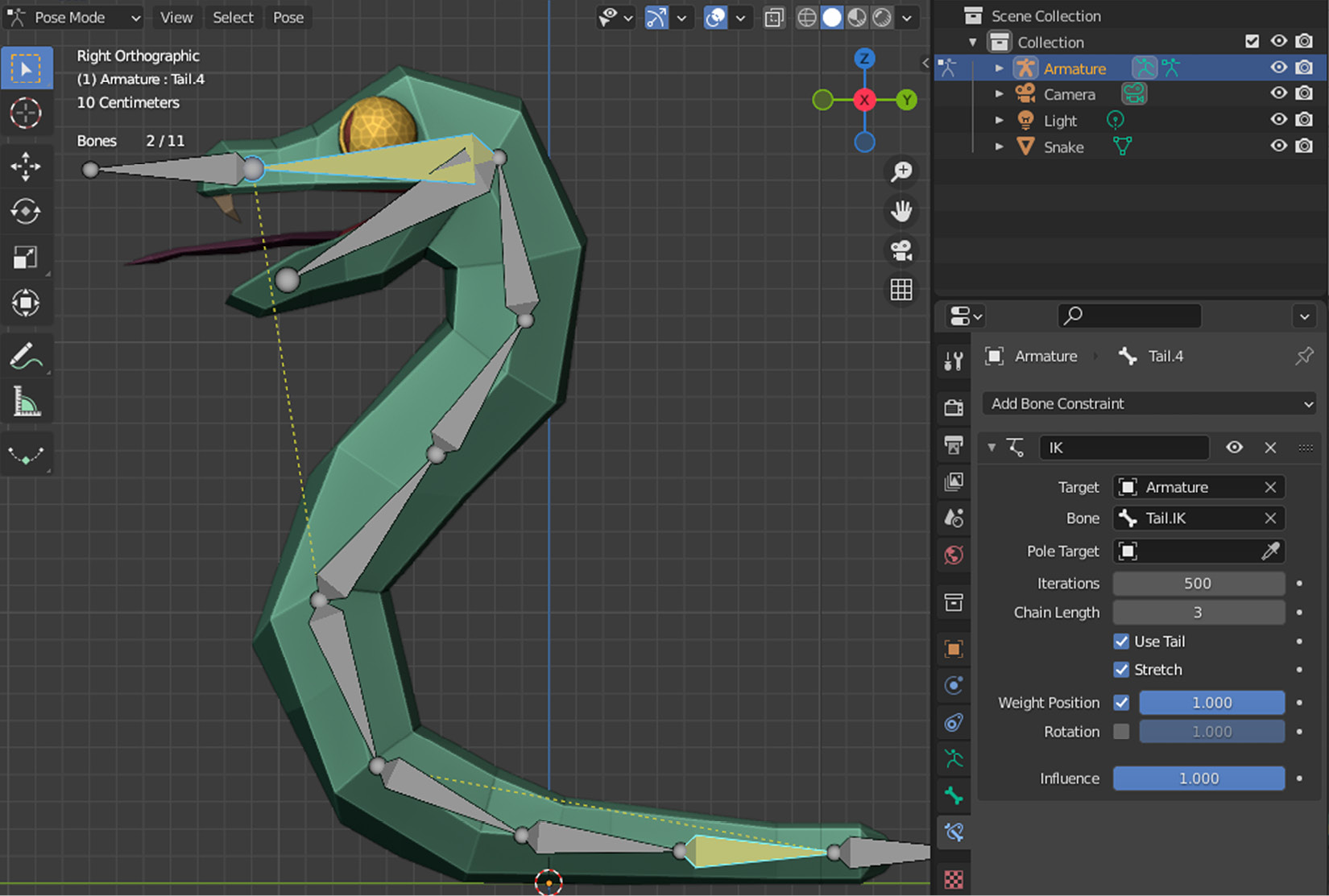
Figure 5.10 – A fully rigged snake
We’ve been doing all of this work so that the armature would be part of the snake. However, if you look at Outliner, you can still see that these two objects are separate. It’s time to really connect the skeleton to the snake’s mesh as follows:
- Switch to Object Mode.
- First select the Snake mesh, then Armature by holding down the Shift key.
- Press CTRL+P to bring up the Set Parent To menu.
- Choose With Automatic Weights.
When you parent the armature to the mesh, two things will happen. First, Snake in Outliner will be moved as a child under the Armature item. Second, Snake will be assigned an Armature modifier that will build the connection between these two objects.
In the end, the armature will designate its bones to nearby vertices so that when a bone moves, it mobilizes the associated vertices. It’s as if some vertices that are closer to a particular bone weigh more in terms of priority. Thus, you won’t see a tail bone move far away vertices that much.
Phew, the rigging is finally complete. As you may have noticed, all of this creating and separating bones, adding constraints, adjusting settings, and so on could sometimes become a tricky business. You get visual clues as to which bone is doing what and how they are connected, but the scene could quickly get cluttered with gizmos. Like anything else, though, you get used to doing it with practice. On that note, you’ll find links to more advanced rigging material in the Further reading section.
We have provided the Snake.Rigged.blend file both in the Start and Finish folders for you to compare your results. You can also use this file as a starting point in the following section. Since we deemed that rigging was necessary for animation and that our rig is done, we can now turn to a new section where we’ll get to know the Animation workspace of Blender.
Animating
We’re about to animate our snake. We’ve prepared a skeleton and introduced two control bones to construct a rig. In this section, we’ll use this setup to create an attack animation. Using the methods presented in this section, you can create different animations for your models and store these animations with the model in the same file.
Let’s switch to the Animation workspace to take advantage of a more suitable set of interfaces. The layout will change to mainly two side-by-side 3D Viewport panels and what looks like a timeline underneath. There are actually two panels at the bottom, as follows:
- Dope Sheet: We’ll work with keyframes soon to mark the defining points when parts of your model move over time. For example, a frog can have one keyframe for its resting position, then another keyframe defined as its highest jump level later in time.
- Timeline: This is a simpler version of Dope Sheet. It is represented with a clock icon and lets you see things at a higher level. We won’t utilize this interface that much, but it’s useful to set the Start and End keyframes of your animations.
Besides these two editors, there is also the Graph Editor, which you can access by clicking the icon in the drop-down menu in the top-left corner of any panel. Actually, let’s do that by changing the left 3D Viewport into a Graph Editor. When you are done, you should see something like the following:
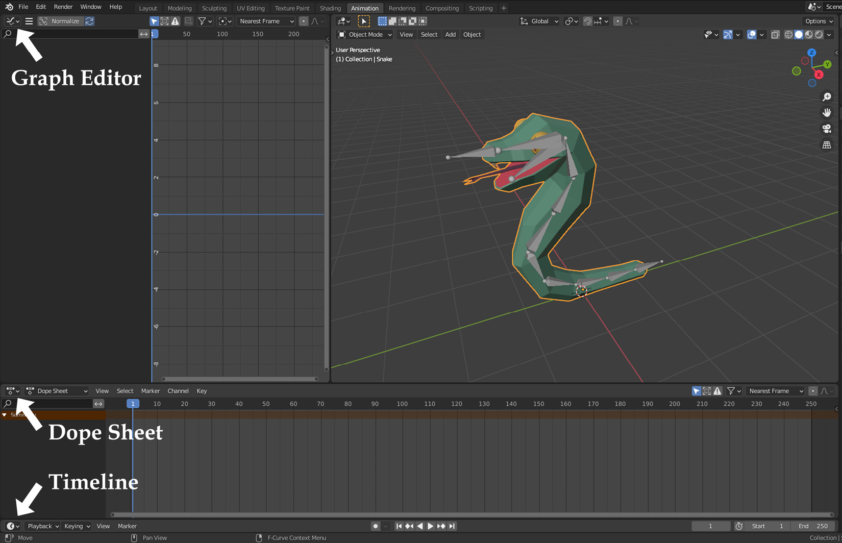
Figure 5.11 – We have further customized the Animation workspace
We have everything we need to animate the snake. We’ll start with an attack animation. For this, we’ll move the head forward and raise the tail to depict a menacing pose. Start by switching the 3D perspective to Right Orthographic by pressing 3 on the numpad and performing the following steps:
- Go into Pose Mode.
- Select the Head.IK bone.
- Press I to insert a keyframe and select Location in the options.
This operation will add a key to the first frame in Dope Sheet as well as populating some elements both in Dope Sheet and Graph Editor. So far, so good. Take a look at what’s added to the animation editors and expand the Head.IK title in both editors to see what exactly is happening under the hood. We are marking the location of the Head.IK bone.
For the next event in the snake’s attack animation, we need to move the snake’s head forward and key (mark) its new location. For this, we need to select a new frame in the timeline as follows:
- Change the frame value from 1 to 10 (just to the left of the Start section in Timeline).
- Press G and move the head slightly to the left and up.
- Press I to insert a keyframe and choose Location again.
This should add more elements – more specifically, curved lines – to Graph Editor. This is good because you can use those curves to fine-tune how the action will start and end—more abruptly or smoothly, which can be used for more dramatic effects. We leave it to your artistic interpretation. What we can do, for now, is finish the head’s motion so that it goes back to its original position, as follows:
- Change the frame value from 10 to 25.
- Press Alt+G to reset its position to the original values.
- Press I to insert a keyframe and choose Location again.
Figure 5.12 shows our progress so far.
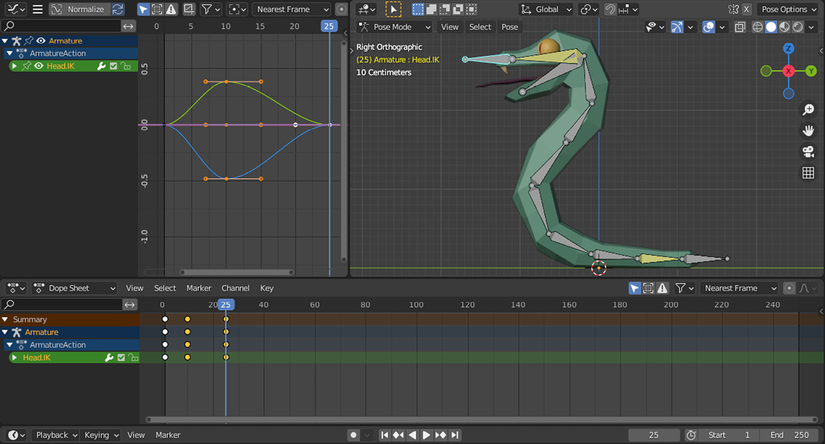
Figure 5.12 – We have animated the head bone via a control bone
In the end, we have moved the torso bones by animating the Head.IK bone. That’s why we have implemented a control bone instead of moving the individual torso bones. Additionally, we haven’t done anything special to the Mouth bone, but that’s also moving to keep up with the head.
Let’s do something similar with the tail, as follows:
- Set the frame to 1.
- Select the Tail.IK bone.
- Press I to insert a keyframe and choose Location.
- Set the frame to 10.
- Press G and move the tail slightly to the top and left.
- Press I to insert a keyframe and choose Location again.
- Set the frame to 25.
- Press Alt+G to reset the position.
- Press I to insert a keyframe and choose Location again.
In this pose, the tail naturally looks angry, which accentuates the head’s motion. By the way, where is your head? If you look in Dope Sheet, the keyframes for the head animation are gone. Blender only displays the keyframes for the selected object to keep the interface clean and simple. You can display everything by toggling off the Only Show Selected button, which looks like a select icon in the header of Dope Sheet. There is a similar button in Graph Editor; if you disable both, you should have something similar to what you see in Figure 5.13.
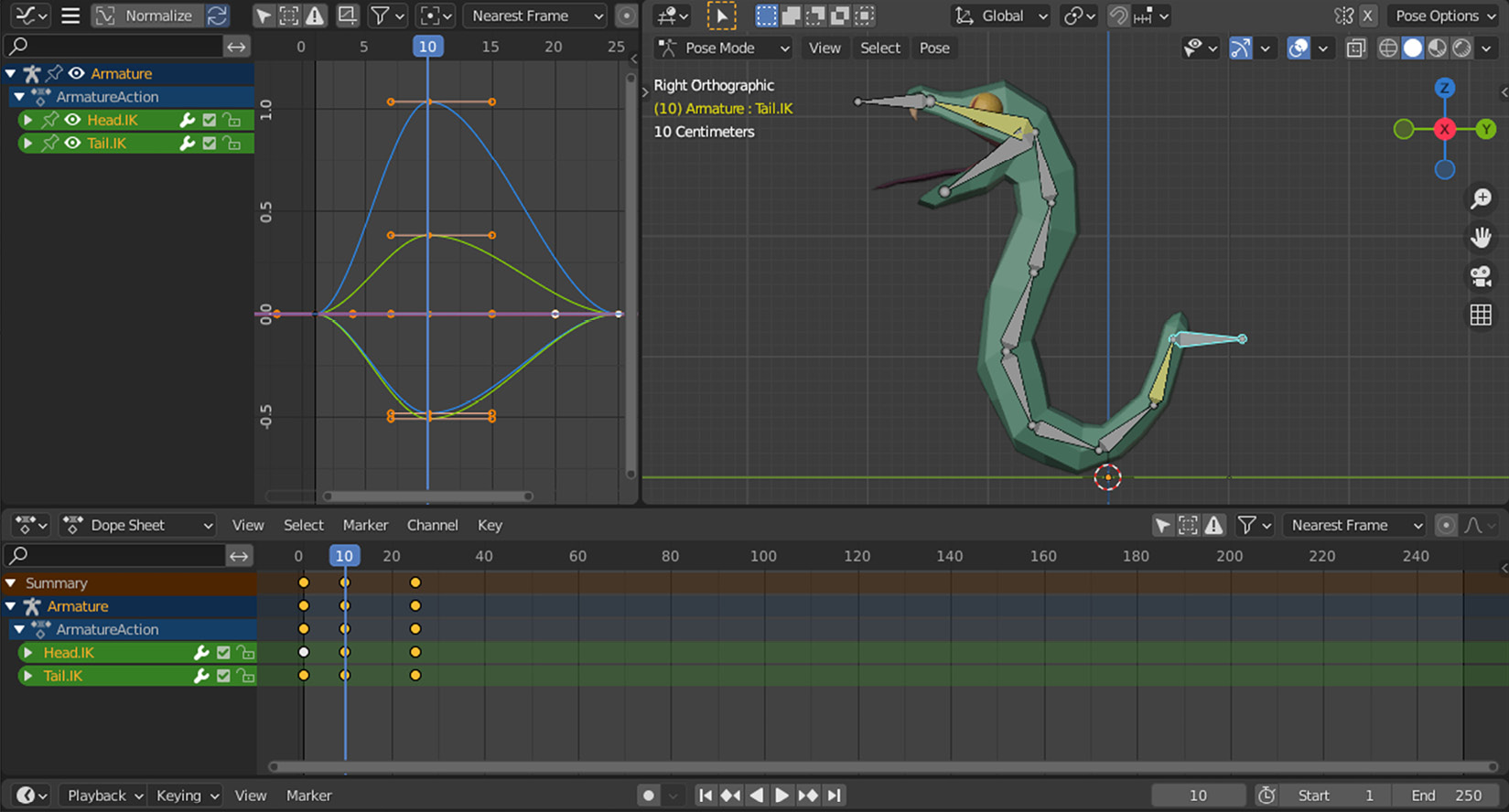
Figure 5.13 – Both the head and tail keyframes are visible in the editors
You can also refer to the Snake.Animated.blend file in the Finish folder.
We’ve completed our first animation. If you would like to create another animation, where would you do it? It seems that we could keep adding more keyframes to the timeline. However, how would we know which keyframes are responsible for a particular animation?
We can answer this question both in Blender and Godot contexts. Actually, once we understand how to create separate animations in Blender for the same model, we’ll have practically prepared our animations to be shipped to Godot. To do this, we’ll discover Action Editor in the following section.
Getting animations ready for Godot
Creating separate Blender files for different animations would be extremely unwieldy. If only we had a way to store multiple animations in the same file. Luckily, there is. We need to use a new interface called Action Editor for that. Let’s see how we can use it to create another action for the snake.
There is a dropdown in the top-left corner of the Dope Sheet panel. Although that whole panel could be considered as the Dope Sheet panel, we have been using its default view. This is similar to how 3D Viewport works. When we were switching between Object Mode and Edit Mode, we were still working in the same 3D Viewport panel but in one of its specialized views. In other words, these dropdowns customize the panel you are in. To switch the Dope Sheet panel to its Action Editor view, perform the following steps:
- Expand the dropdown that shows Dope Sheet.
- Select Action Editor in the options.
This will reveal the title of our first animation, ArmatureAction, in the middle portion of the Action Editor header. This is a lackluster action name. The snake deserves better. Let’s change it by clicking its text and typing Attack. Now, you have just changed the default name to something you can easily keep track of. Moreover, when we import this model into Godot and we want to trigger the correct animation sequence, we’ll use this action name. Let’s create more actions as follows:
- Click on the second icon next to the action title (the icon with stacked papers).
- Change this new action’s title to Idle.
This will actually create a copy of the first animation. Except for its title, everything is the same, but we can now change the features of the animation that match the title we just gave. In most games, the idle state of characters usually looks calm, but they have a slight bobbing up and down motion that indicates the character is alive but otherwise in a neutral state. Our idle action involves performing the following steps:
- Set the frame to 10.
- Select the Head.IK bone and reset its position by pressing Alt+G.
- Press G and move the bone ever so slightly downward.
- Press I and choose Location.
- Repeat Steps 2 to 5, but move the Tail.IK bone slightly upward.
Let’s do one more thing and test our new action. Change the End value in Timeline to 25 and click the play button. This will let you see the action in a looped manner so that you get a sense of whether the locations in the animation are good enough. Make more corrections to the location of the head and tail control bones if you would like, but remember to set their values by pressing I.
Our snake is idling, up and down, perhaps waiting for a target to attack. By using the dropdown to the left of the action’s title, you can switch between different actions.
Congratulations! You have officially created two animations. If, at times, it was difficult to follow the instructions, you can find a fully finished example in the Finish folder in the Snake.blend file for further studying.
We have done a lot in this chapter. It’s time to summarize our efforts.
Summary
This chapter started off with a discussion about which software (Blender versus Godot) would be suitable for animations. We exemplified different cases of animation and determined that Blender is the right choice for animating systems that have individually moving parts.
We then discussed the importance of good geometry, better known as topology, since not everything that looks good is good enough from an animation perspective. Once the system is in motion, the vertices, faces, and edges will act like a wrapper around a skeleton. If you know you’ll be animating your model, you might be careful in how you create the geometry better ahead of time.
Nevertheless, if such an early option is not always possible, to prevent tearing and creasing that might occur in certain areas of a model, we introduced the grab option. It can help you resolve problematic parts by moving them to a different location.
As soon as the distribution of vertices is in a favorable place, then the rigging can start. This is, in fact, one of the most advanced topics for most artists who are learning any 3D modeling software. It helps sometimes to think of rigging as a bunch of strings that control a puppet. Like a puppet master, you need to know which string controls which parts. To that end, we introduced IK, which has advantages over a more direct, also known as FK, approach.
After we created a rig for a snake, we discovered the animation workspace. Since the rigging depended on control bones via IK, our animation was done effortlessly. Along the way, we learned how to move parts of a rig and keyframe their properties. In our simple case, it was only location, and we kept the motion on one axis.
Lastly, we got to know how we could store two animations, rather actions, for the same model. Once you have properly labeled actions, not only will it be easier for you to find them in Blender in the future, but you will also see the benefit of this practice later in Godot chapters.
You have completed five chapters that took you from creating models to adding animations to your models. Along the way, you’ve also learned how to construct and apply materials and textures. In the following chapter, we’ll investigate how to export our work from Blender.
Further reading
We mentioned the importance of topology, and it could be challenging to know what constitutes good or bad topology. So, to see more examples and benefit from other people’s expertise, refer to the following links:
- https://blender.stackexchange.com/questions/140963/do-i-have-bad-topology
- https://www.reddit.com/r/blenderhelp/comments/speyjs/is_this_bad_topology/
- https://www.pluralsight.com/blog/film-games/ngons-triangles-bad
Some 3D practitioners specialize only in animation. Although it’s possible to animate some Blender objects without rigging them, for example, cameras and lights to move them around the scene, most online courses usually cover rigging and animation topics together. The following is a list of online courses and material for you to further your knowledge in both of these domains:
- CG Cookie: https://cgcookie.com/courses?sort_category=140,179
- Udemy:
Additionally, while you are browsing for more training content, you might come across a topic called Weight Painting, which is helpful in determining how the rigging will prioritize the nearby vertices. We left it out for brevity’s sake, but it’s a topic you’ll most likely want to cover if you want to be more thorough.
In the following chapter, we’ll be slowly transitioning from Blender to Godot. So, this chapter was really the last hands-on Blender chapter. If you want to know more about what Blender can do, there are some really useful resources out there, in both written and video formats, offered by Packt Publishing, such as the following resources:
- Blender 3D By Example by Oscar Baechler and Xury Greer
- Blender 3D Modeling and Animation: Build 20+ 3D Projects in Blender by Raja Biswas
- The Secrets to Photorealism: The PBR/Blender 2.8 Workflow by Daniel Krafft